CrowPanel Advance 7.0-HMI ESP32 AI Display
Model DIS02170A
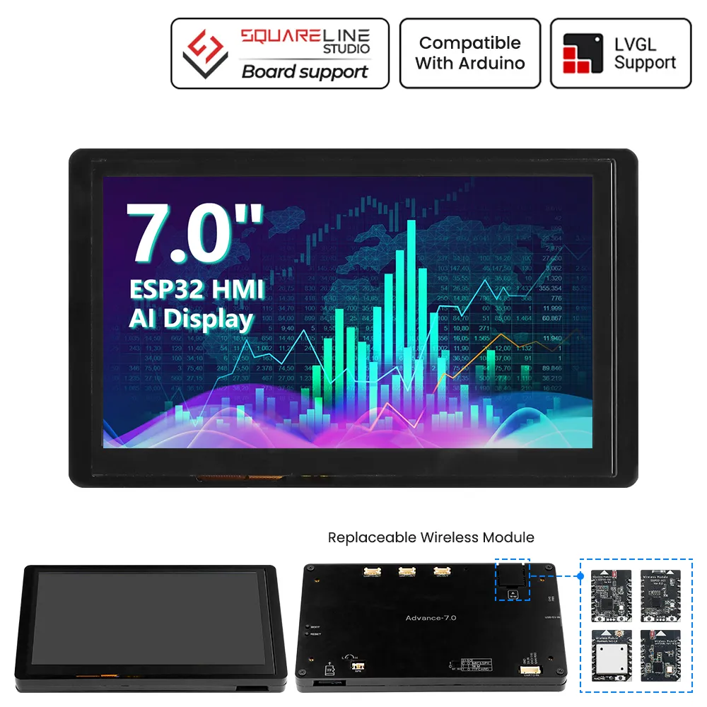
Version 1.0
Pin Output:
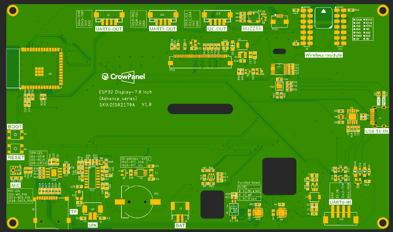
Functional description of the product's internal interfaces:
| Pin Name | Description | Connector Type |
|---|---|---|
| SPK | Output audio signals to connect to speakers. The main board comes with a power amplifier chip circuit. | PH2.0-2P |
| PWR | Power LED. | |
| RST | Reset button. Press it to reset the system. | |
| boot | Used to enter programming mode or for button testing. Hold this button down while powering on, then release to enter download mode. Alternatively, after powering on, hold this button down, press the RESET button, release the RESET button, and then release this button to enter download mode. When download mode is not required, this button functions as a standard button. Note: Under normal circumstances, the screen is in automatic download mode; no button presses are required. | |
| UART0-OUT | Builds communication between Logic modules, including the serial communication module and the print module. | PH2.0-4P |
| UART1-OUT | Builds communication between Logic modules, including the serial communication module and the print module. | PH2.0-4P |
| UART0-IN | Input power supply and serial communication functionality | XH2.54-4P |
| I2C-OUT | Establish communication between the microcontroller and peripheral devices. | PH2.0-4P |
| BAT | Connect the lithium battery. (with battery charging circuit)(Input voltage: 3.7–4.2 V) | PH2.0-2P |
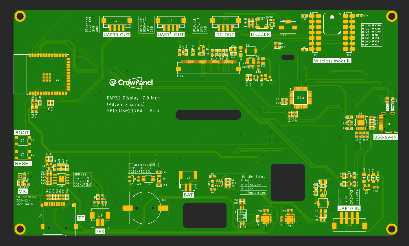
Product External Interface Functions:
| 7.0-inch HMI port | pin number | Electrical Characteristics |
|---|---|---|
| UART0-OUT | RX(IO44); TX(IO43) RX; | Output voltage: 3.3V Output current: 1A max. Use: Power supply output and communication. |
| UART1-OUT | RX(IO19); TX(IO20) RX; | Output voltage: 3.3V Output current: 1A max. Use: Power supply output and communication. |
| UART0-IN | RX(IO44); TX(IO43) RX; | Input voltage: 5V ± 5%. 5.5V max. Input current: 2A max. Purpose: Power supply input and communication. |
| I2C | SDA(IO15); SCL(IO16) ; | Output voltage: 3.3V Output current: 1A max. Use: Power supply output and communication. |
| SPK | I2S_LRCLK(IO6);I2S_BCLK(IO5);I2S_SDIN(IO4); | Maximum output current: 20mA Signal type: 3.3V logic level, digital control signal |
| SD Card Slot | MOSI(IO6); MISO(IO4); CLK(IO5); CS(3.3V) | Maximum output current: 20mA Signal type: 3.3V logic level, digital control signal |
| LCD Backlight | (PCA9557)IO1 | Maximum output current: 20mA Signal type: 3.3V logic level, digital control signal |
| I2S MIC | MIC_SD(IO20);MIC_WS(IO2);MIC_CLK(IO19) | Maximum output current: 20mA Signal type: 3.3V logic level, digital control signal |
| BUZZER | IO8 | Maximum output current: 20mA Signal type: 3.3V logic level, digital control signal |
Switching Function Keys
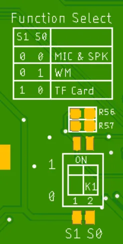
| S1 | S0 | effective function |
|---|---|---|
| 0 | 0 | MIC&SPK |
| 0 | 1 | WM(wireless module) |
| 1 | 0 | TF Card |
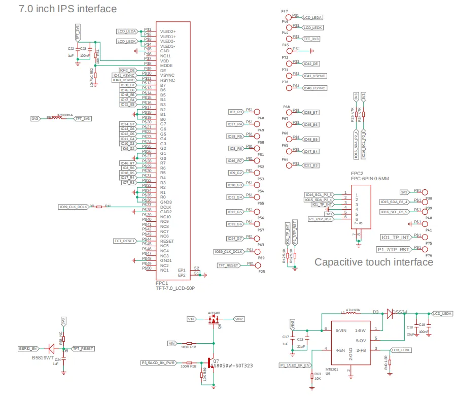
Schematic:
ESP32-S3 and ISP Display Wiring Pins:
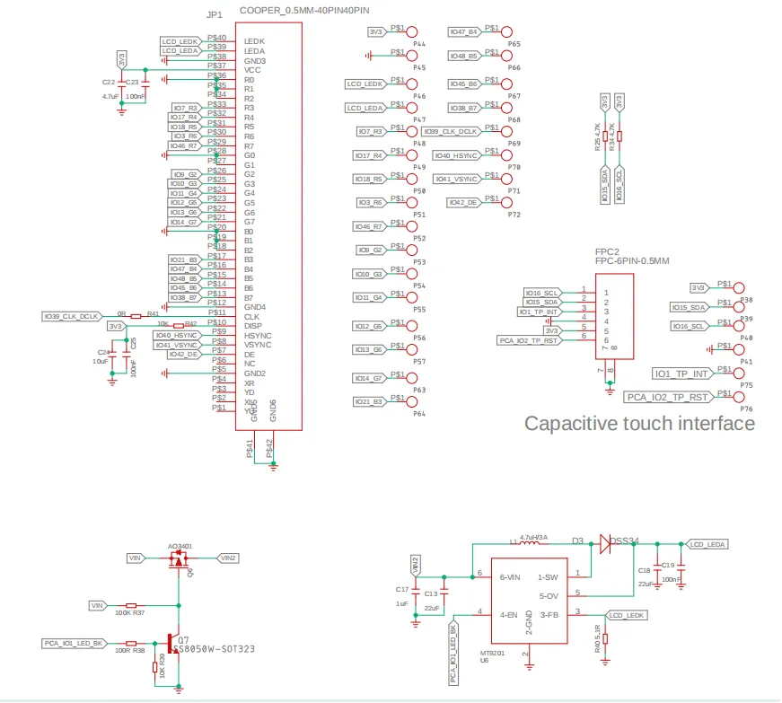
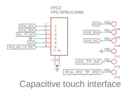
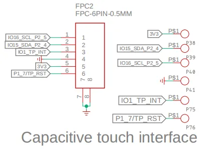
ESP32-S3 and Touch Driver Wiring:
i2c address: 0x5D.
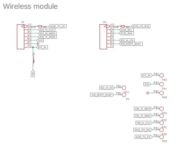
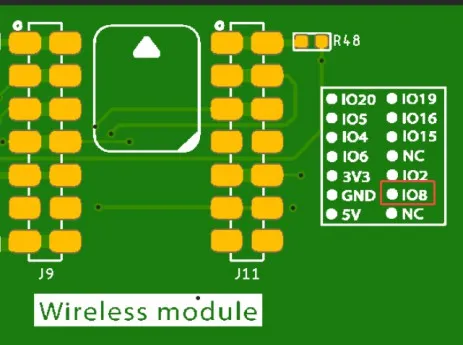
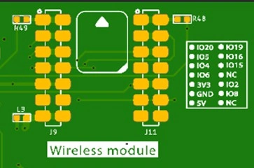
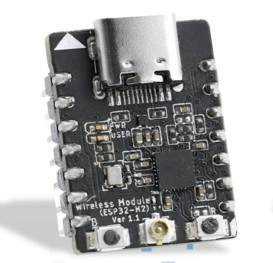
ESP32-S3 and wireless module wiring pins:
Version 1.2
Pin Output:
| 7.0-inch HMI port | pin number | Electrical Characteristics |
|---|---|---|
| UART0-OUT | RX(IO44); TX(IO43) RX; | Output voltage: 3.3V Output current: 1A max. Use: Power supply output and communication. |
| UART1-OUT | RX(IO19); TX(IO20) RX; | Output voltage: 3.3V Output current: 1A max. Use: Power supply output and communication. |
| UART0-IN | RX(IO44); TX(IO43) RX; | Input voltage: 5V ± 5%. 5.5V max. Input current: 2A max. Purpose: Power supply input and communication. |
| I2C | SDA(IO15); SCL(IO16) ; | Output voltage: 3.3V Output current: 1A max. Use: Power supply output and communication. |
| SPK | I2S_LRCLK(IO6);I2S_BCLK(IO5);I2S_SDIN(IO4); | Maximum output current: 20mA Signal type: 3.3V logic level, digital control signal |
| SD Card Slot | MOSI(IO6); MISO(IO4); CLK(IO5); CS(3.3V) | Maximum output current: 20mA Signal type: 3.3V logic level, digital control signal |
| LCD Backlight | P3.5(STC8H1K28) | Maximum output current: 20mA Signal type: 3.3V logic level, digital control signal |
| Backlight Adjustment | P1.1(STC8H1K28) | |
| I2S MIC | MIC_SD(IO20);MIC_WS(IO2);MIC_CLK(IO19) | Maximum output current: 20mA Signal type: 3.3V logic level, digital control signal |
| BUZZER | P2.7(STC8H1K28) | Maximum output current: 20mA Signal type: 3.3V logic level, digital control signal |
| TP_RST | P1.7(STC8H1K28) | |
| power amplifier MUTE | P3.7(STC8H1K28) | |
| power amplifier SHUT | P3.6(STC8H1K28) |
Switching Function Keys:
| S1 | S0 | effective function |
|---|---|---|
| 0 | 0 | MIC&SPK |
| 0 | 1 | WM(wireless module) |
| 1 | 0 | TF Card |
| 1 | 1 | MIC&TF Card |
ESP32-S3 and wireless module wiring pins:
Schematic:
ESP32-S3 and ISP Display Wiring Pins:
ESP32-S3 and Touch Driver Wiring:
i2c address: 0x5D.
Version 1.3
| 7.0-inch HMI port | pin number | Electrical Characteristics |
|---|---|---|
| UART0-OUT | RX(IO44); TX(IO43) RX; | Output voltage: 3.3V Output current: 1A max. Use: Power supply output and communication. |
| UART1-OUT | RX(IO19); TX(IO20) RX; | Output voltage: 3.3V Output current: 1A max. Use: Power supply output and communication. |
| UART0-IN | RX(IO44); TX(IO43) RX; | Input voltage: 5V ± 5%. 5.5V max. Input current: 2A max. Purpose: Power supply input and communication. |
| I2C | SDA(IO15); SCL(IO16) ; | Output voltage: 3.3V Output current: 1A max. Use: Power supply output and communication. |
| SPK | I2S_LRCLK(IO6);I2S_BCLK(IO5);I2S_SDIN(IO4); | Maximum output current: 20mA Signal type: 3.3V logic level, digital control signal |
| SD Card Slot | MOSI(IO6); MISO(IO4); CLK(IO5); CS(3.3V) | Maximum output current: 20mA Signal type: 3.3V logic level, digital control signal |
| LCD Backlight | P3.5(STC8H1K28) | Maximum output current: 20mA Signal type: 3.3V logic level, digital control signal |
| Backlight Adjustment | P1.1(STC8H1K28) | |
| I2S MIC (LMD3526B261-OFA01) | MIC_SD(IO20);MIC_CLK(IO19) | Maximum output current: 20mA Signal type: 3.3V logic level, digital control signal |
| BUZZER | P2.7(STC8H1K28) | Maximum output current: 20mA Signal type: 3.3V logic level, digital control signal |
| TP_RST | P1.7(STC8H1K28) | |
| power amplifier MUTE | P3.7(STC8H1K28) | |
| power amplifier SHUT | P3.6(STC8H1K28) |
ESP32-S3 and wireless module wiring pins:
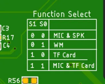
Schematic diagram of function selection:
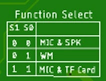
Switching Function Keys:
| S1 | S0 | effective function |
|---|---|---|
| 0 | 0 | MIC&SPK |
| 0 | 1 | WM(wireless module) |
| 1 | 1 | MIC&TF Card |
Version update points:
Version 1.2
① Version 1.2 updated the control of backlight on the basis of the original, the backlight of version 1.2 is controlled by STC8H1K28 microcontroller, and the backlight is lit in the program by sending the value to this microcontroller address (0x30). The values are 0x05, 0x06, 0x07, 0x08, 0x09 and 0x10, where 0x05 switches off the backlight and 0x10 is the maximum brightness.
② Version 1.2 has a new option for function switching, see above for details.
To set a different brightness level, you must first send 0x10 to turn on the screen, and then send another value to adjust the brightness.
Version 1.3
① Version 1.3 introduces an updated backlight control function. In this iteration, the backlight is managed by the STC8H1K28 microcontroller. The programme illuminates the backlight by transmitting numerical values to the microcontroller's address (0x30). Brightness adjustment spans 0-245 levels, where 0 denotes maximum brightness, 244 represents minimum brightness, and 245 disables the backlight.
The buzzer control principle mirrors that of the backlight: sending 246 activates the buzzer, while sending 247 deactivates it.
Version 1.4
Only the button component has been updated. All other hardware and I/O pins remain the same as in the 1.3 version.
Version 1.5
The hardware and software have not been modified; only the silkscreen has been updated. You can continue to use the 1.3 program and instructions.
Platforms Supported

| ESPHome | SquareLine Studio | Meshtastic |
|---|---|---|
 | ||
| ESPHome View Tutorials -- V1.0 ESPHome View Tutorials -- V1.2 ESPHome View Tutorials -- V1.3/V1.4/V1.5 | SquareLine Studio View Tutorials -- V1.0 SquareLine Studio View Tutorials -- V1.2 SquareLine Studio View Tutorials -- V1.3/V1.4/V1.5 | Meshtastic View Tutorials Only version 1.0 supports Meshtastic. |
| Thread Wireless | ESP-matter |
|---|---|
 | |
 | |
Resources
Github link:
(This GitHub link usually may contain 3D files, schematics, program code, factory firmware, factory sourcecode and other materials. Please click to view.)
Code lib link:
Wireless link:
How to buy
Please visit this page to purchase ESP32 Display-7.0 inch(Advance_Series).
Support
If you encounter any issues while using the service, you can contact us via the social media links in the bottom-right corner of elecrow or send an email to techsupport@elecrow.com for technical support.