Smart Pump Shield
Description
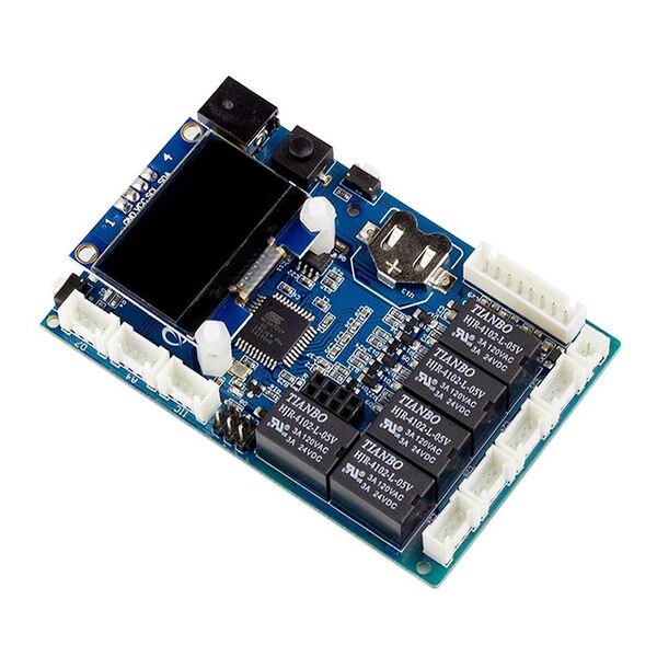
The smart Pump Shield is based on Arduino Lenardo which has integrated into the mainboard. The mainboard will send the command to turn on the pump and suck water into the switch, the switch will separate the stream and will give just enough water for your plants. Then it will close the pump and the switch and continue to check when does your plant needs water. We add a RTC to set timing watering and a 0.96 inch OLED to show the time and the soil moisture status.
Model: PSMC18001M
Features
- Eliminates the need for messy jumpers and breadboards, connect all sensors and modules with ease!
- Integrated Arduino UNO into the main board, program it easily.
- Power the board with single 12V power supply directly.
- 4 interfaces for sensors, one interface for water switch and one interface for motor or pump.
Specifications
| Item | Value |
|---|---|
| Size of the box | 25 x 19 x 5.7cm |
| Length of water pipe | 5m |
| Length of 4 Pin Crowtail cable | 1m |
Interfaces
Usage
Hardware Connection
Connect the Smart Pump Board to your computer system
Attach the micro USB side of the cable to the Smart Pump Board and the other end of the USB cable to an USB port in your computer.
Notice:Please power the board by DC power when you upload the code 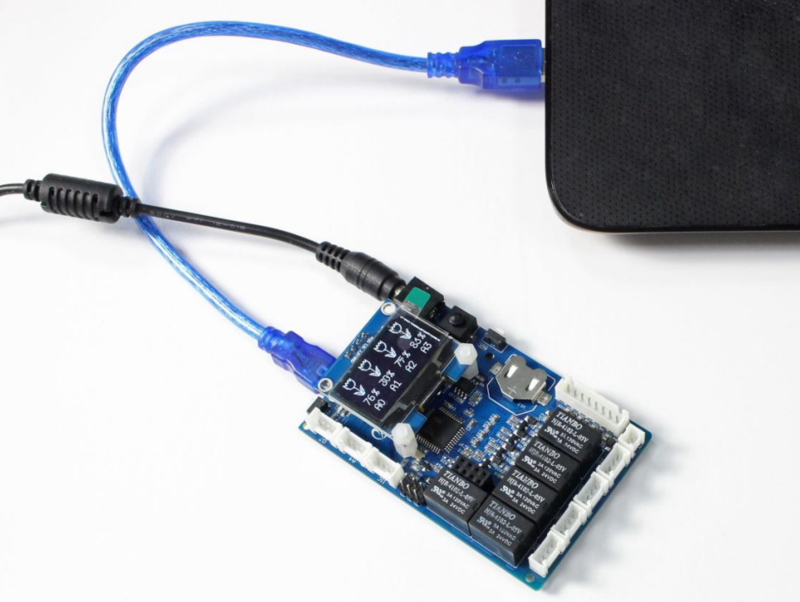
Software
STEP 1. Download the library and the program
- 1.Download the Library: Watering_kit_library.zip and extract it. Copy it to the file-libraries in the arduino IDE file,i.e. D:\Program Files (x86)\Arduino\libraries.
- 2.Download the program at watering_kit.zip Extract the file from the zip file. The filename is watering_kit.ino
STEP 2. Configure which controller board will be used in the Arduino IDE
On top of the Arduino IDE, click “Tools>Board>” and select “Arduino Leonardo”from the available options.

STEP 3. Configure which communication port to use
The Arduino IDE needs to know in which USB computer port the Arduino Leonardo controller is connected in order to communicate with it.
To do so, select “Tools>Port” and select the COM port that indicates Arduino Leonardo. Please note that the actual numbers after the “COM” word will vary from computer to computer, so they could be different from the ones shown in the figure.

Once completed, proceed to the next section to upload the program into the Arduino IDE and program the Arduino Leonard controller in the Smart Pump Board.
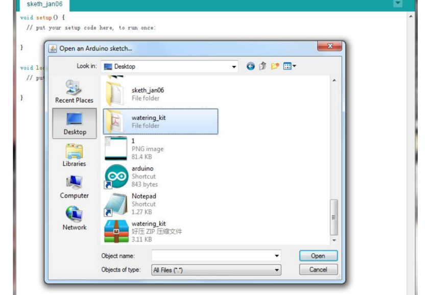
STEP 4. Load the program in the Arduino IDE
STEP 5. Click the  to upload the code to the Arduino board
Assembling the components
Note: For an overview of the process please watch this YouTube video . 1. Attach the cable to the Soil Humidity Sensors as shown in the figure. Repeat for each sensor.
 2. Connect the Soil Humidity Sensors to the Smart Pump Board
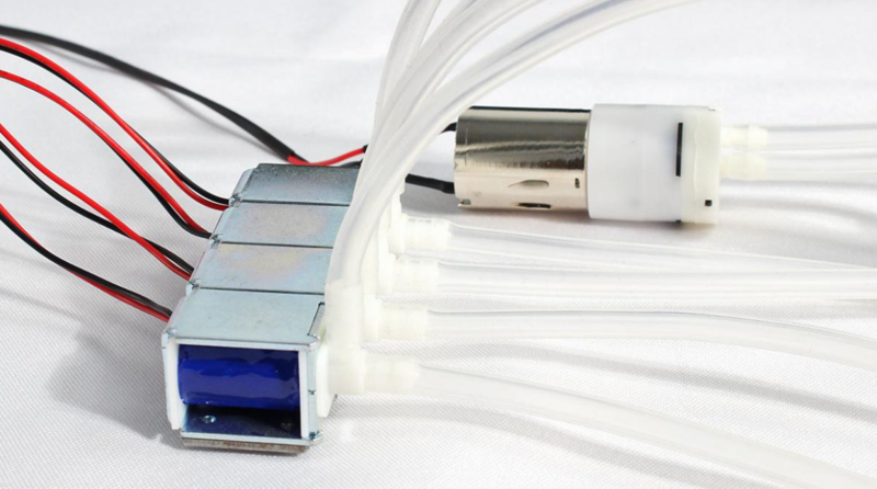
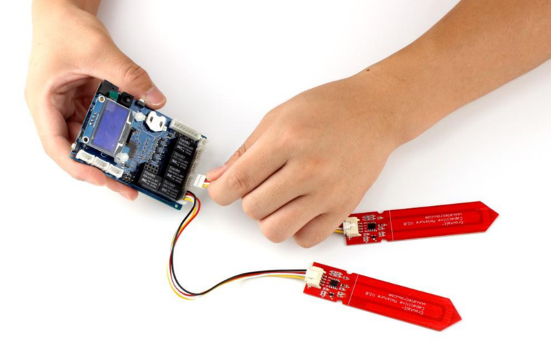 3. Connect the Water Pump and the Four-way Valve to the Smart Pump Board
 4. Cut the plastic water pipe
First cut: for water source to water pump input (depends on water source height)
Second cut: water pump output to five-way valve input. (depends on how you locate the plants)
Third cut: 4 pieces for the output valves in the five-way valve to the input of the four-way water valves. (depends on how you locate the plants)
Fourth cut: 4 pieces for the output valves of the four-way water valves to the soil where each plant is planted. (depends on how you locate the plants)

5. Connect the Water Pipes
Cut the water pipe and divide them to 6 parts. Make sure the pipe that goes inside the water source will be long enough to reach the water. We’ll connect 2 of the pipes to the pump, one sucks the water from the water sources while the other connects to the five-way water pipe.

Connect five pipes to the valves.
 6. Power it Up!
Just power the board with single 12V power supply directly! The shield will split the power between the Leonardo and the other devices. That way, the Leonardo will get 5V while the pump and the switch will get 12V. 
FAQs
You can list you question here or contact with techsupport@elecrow.com for technology support.


