Mechanical_Keyboard_ESP32-S3
Description
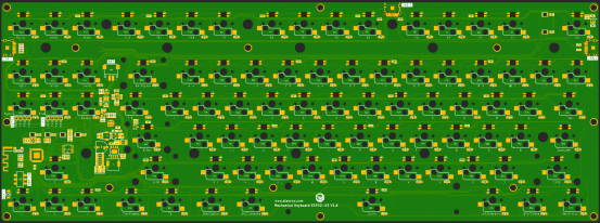
Mechanical_ Keyboard_ ESP32-S3 is an open-source mechanical keyboard backplane based on the ESP32-S3 main control chip.
It carries 87 universal mechanical keyboard shaft sockets and SMD3528 reverse labeled (6028) programmable RGB LEDs (supporting WS2812/SK6812 chips), 3 USB power/program burning interfaces, PH2.0 lithium battery power interface, and 2 pre reserved 1 * 4PIN 2.54mm spacing pin interfaces. All key functions and RGB light effects can be defined and designed through program programming.
The keyboard supports Bluetooth wireless connection and USB wired connection. It supports the Arduino open-source programming platform, making it particularly suitable for open-source creators and DIY design enthusiasts.
Model: DIS03024H

PinOut
| PWR | Power LED. |
|---|---|
| CAP | Letter case toggle indicator. |
| BT1 | Bluetooth Channel 1 toggle indicator. |
| BT2 | Bluetooth Channel 2 toggle indicator. |
| BT13 | Bluetooth Channel 3 toggle indicator. |
| CABLE | USB wired access indicator/lithium battery charging indicator. |
| BOOT | Download button.Push it to start the Firmware download mode.Through USB interface, users can download the upgraded firmware to modify the underlying software and add new function to the hardware. |
| USB-C*3 | USB-C interface, which is used as the power supply of the keyboard board and the communication interface between the PC and ESP32 S3, and can charge the lithium battery when an external lithium battery is connected. |
| BAT | PH2.0-3.7V lithium battery interface, can be used for external 3.7V lithium battery |
| ON/OFF | System power toggle switch. |
| ESP32(UART) | ESP32 UART serial communication interface is reserved. |
| STC8(UART) | STC UART serial communication interface is reserved. |
Feature
- Integrated ESP32-WROOM-32 module and and STC8G1K08 chip, built-in 384KB ROM, 512KB SRA, 16KB RTC SRAM, onboard 4MB Flash;
- Xtensa 32-bit LX7 dual core processor, with a main frequency of 240MHz;
- built-in wireless communication 2.4 GHz Wi-Fi (802.11 b/g/n) and Bluetooth 5.0;
- Support development environment Arduino IDE, Micro python;
- 87 universal mechanical keyboard axes and SMD3528 anti stick (6028) programmable RGB LEDs (supporting WS2812/SK6812 chips);
- Support for USB charging and USB/lithium battery power supply.
Specification
- Input voltage of TYPE C USB: DC-5V
- Input voltage of PH2.0 lithium battery interface: 3.7V-4.2V
- Operating temperature range: -10 ° C~65 ° C
- Size: 130mm*354mm (W*L)
Development environment configuration
- 1.Please go to the official website https://www.arduino.cc/ to download the Arduino IDE development tool and download the corresponding library file, install the tool. Open the Arduino IDE after the installation:
- 2.Click the "File" menu, select "Preferences" in the drop-down menu, and then the picture will appear: Unzip the downloaded library file and put it in the libraries folder.
- Add the ESP32 S3 URL as follows:
https://raw.githubusercontent.com/espressif/arduino-esp32/gh-pages/package_esp32_index.json 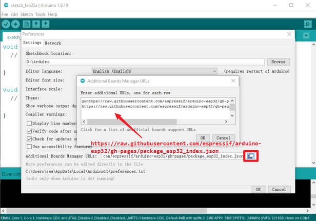
- The tool automatically downloads and updates the corresponding model, check the steps as shown in the figure:
- warn:
please install esp32 version 2.0.3, if you install another version,some modules may go wrong.
Software settings:
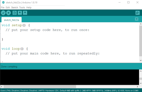
- 1.Under the "Tools" menu, see "Board: ESP32-XXX" and select ESP32 Dev MODULE as shown in the figure.
- 2.After connecting the Mechanical_Keyboard_ESP32-S3 to the computer through the TYPE-C USB cable, the computer will automatically recognize the USB COM port (if the USB is not recognized successfully, please disconnect the USB cable and connect to the computer, press and hold the BOOT button, and connect the computer again at power-on).
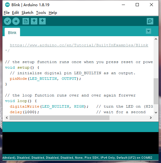
- 3.After the USB COM port is successfully recognized, open the Arduino IDE to download a sample code, as shown in the following figure: File->Examples->Basics->Blink.
 The code that opens is as follows:
- Noted:
- If the CH340 driver is not installed on your PC, please install the CH340 driver first, or switch the SWITCH to the USB position and connect it with a USB cable.
Download process
- 1.Connect the keyboard and computer through a USB to type-c data cable;
- 2.Click on the tool on the arduino software and select the corresponding serial port number;
- 3.Click "upload" to upload the program to the ESP32 keyrboard
- Until the prompt upload is successful, as shown in the figure:
I/O Port
| ESP32 S3 | Mechanical_Keyboard_ESP32-S3 | ESP32 S3 | Mechanical_Keyboard_ESP32-S3 | |
|---|---|---|---|---|
| GPIO0 | BOOT | GPIO1 | KEY_IN5(6X17 Matrix keyboard line control signal) | |
| GPIO2 | KEY_IN4(6X17 Matrix keyboard line control signal) | GPIO3 | KEY_IN3(6X17 Matrix keyboard line control signal) | |
| GPIO4 | KEY_IN2(6X17 Matrix keyboard line control signal) | GPIO5 | KEY_IN1(6X17 Matrix keyboard line control signal) | |
| GPIO6 | KEY_IN0(6X17 Matrix keyboard line control signal) | GPIO7 | KEY_OUT0(6X17 Matrix keyboard line control signal) | |
| GPIO8 | KEY_OUT1(6X17 Matrix keyboard line control signal) | GPIO9 | KEY_OUT2(6X17 Matrix keyboard line control signal) | |
| GPIO10 | KEY_OUT3(6X17 Matrix keyboard line control signal) | GPIO11 | KEY_OUT4(6X17 Matrix keyboard line control signal) | |
| GPIO12 | KEY_OUT5(6X17 Matrix keyboard line control signal) | GPIO13 | KEY_OUT6(6X17 Matrix keyboard line control signal) | |
| GPIO14 | KEY_OUT7(6X17 Matrix keyboard line control signal) | GPIO15 | KEY_OUT8(6X17 Matrix keyboard line control signal) | |
| GPIO16 | KEY_OUT9(6X17 Matrix keyboard line control signal) | GPIO17 | KEY_OUT10(6X17 Matrix keyboard line control signal) | |
| GPIO18 | KEY_OUT11(6X17 Matrix keyboard line control signal) | GPIO19 | USB_D - differential signaling | |
| GPIO20 | USB_D + differential signaling | GPIO21 | KEY_OUT12(6X17 Matrix keyboard line control signal) | |
| GPIO26 | NC | GPIO27 | SPIHD | |
| GPIO28 | SPIWP | GPIO29 | SPICS0 | |
| GPIO30 | SPICLK | GPIO31 | SPIQ | |
| GPIO32 | SPID | GPIO33 | NC | |
| GPIO34 | NC | GPIO35 | SCL | |
| GPIO36 | SDA | GPIO37 | NC | |
| GPIO38 | KEY_OUT13(6X17 Matrix keyboard line control signal) | GPIO39 | KEY_OUT14(6X17 Matrix keyboard line control signal) | |
| GPIO40 | KEY_OUT15(6X17 Matrix keyboard line control signal) | GPIO41 | KEY_OUT16(6X17 Matrix keyboard line control signal) | |
| GPIO42 | BAT_DET_CON | GPIO43 | ESP32-U0TXD | |
| GPIO44 | ESP32-U0RXD | GPIO45 | NC | |
| GPIO46 | NC | GPIO47 | NC | |
| GPIO48 | RGB_DI |
| STC8G1K08 | Mechanical_Keyboard_ESP32-S3 | STC8G1K08 | Mechanical_Keyboard_ESP32-S3 | |
|---|---|---|---|---|
| P1.0 | CABLE | P1.1 | BT2 | |
| P1.2 | BT3 | P1.3 | BAT_DET_CON | |
| P1.4 | SDA | P1.5 | SCL | |
| P1.6 | BT1 | P1.7 | NC | |
| P3.0 | STC_TXD | P3.1 | STC_RXD | |
| P3.2 | NC | P3.3 | ON/OFF | |
| P3.4 | CHRG | P3.5 | BAT_DET | |
| P3.6 | PWR | P3.7 | CAP |
Example
- Before using the Mechanical_Keyboard_ESP32-S3 keyboard, you need to flash the program firmware of STC8G1K08.
- Example1. The STC8G1K08 programming program is downloaded through the USB to serial port module by reserving the STC8 UART interface.
The wiring method is as follows:
| STC8 UART | USB TO TTL |
|---|---|
| GND | GND |
| 3V3 | VO-3V3 |
| RXD | TXD |
| TXD | RXD |
- Open the "stc-isp-v6.91M.exe" STC single-chip microcomputer special programming tool in the STC8 firmware and programming tool folder, and connect the USB to serial port module with the computer through the USB data cable.
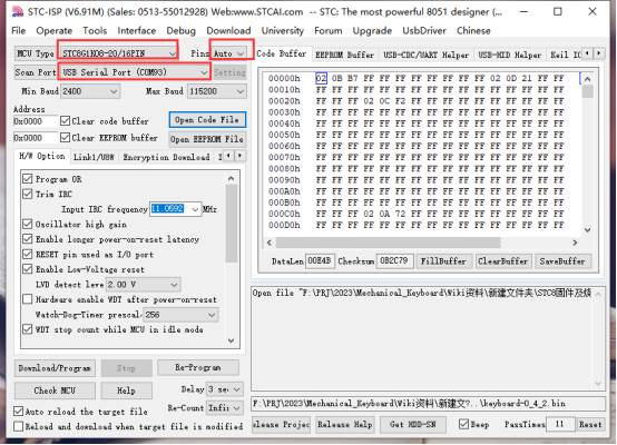
The "stc-isp-v6.91M.exe" tool interface is as follows:

- Select STC8G1K08-20/16PIN, click Auto to automatically identify and select COM port (confirm that it is the COM port of the USB to serial port module you access), and keep other settings as default.
- Click "Open Code File" in the downloading tool and select the "keyboard-0_4_2.bin" file in the "KEYBOARD_STC_BIN" folder.
- Click "Download/Program" to start flashing the firmware.
- Special note: After clicking "Download/Program", the downloading tool print window prints "Checking target MCU ... ", disconnect the STC8G1K08 from the 3V3/GND connection of the USB to serial port module, and power it back on to perform the downloading normally.
- Until the prompt download is successful, as shown in the figure:
- Example2. Use the Arduino IDE to flash the sample program for ESP32-S3.
Before flashing the sample program, copy the used library files to the "libraries" folder, as shown in the following figure.Open the library file in the "Arduino Program Source" folder and copy "ESP32-BLE-Keyboard-0.3.2-beta" and "FastLED" to the Arduino IDE's libraries folder.

- Use the Arduino IDE software to open the "keyboard_main.ino" sample program in the sample code folder.
-
Note: After the program downloading is completed, you need to toggle the power switch on the keyboard board, power on and reset again, and the mechanical keyboard can work normally!
-
Wireless Bluetooth keyboard connection mode usage demo:
The sample program defaults to "FN+1", "FN+2", and "FN+3" key combinations for Bluetooth channel switching, and the corresponding "BT1", "BT2", "BT3" on the keyboard will always light up for 3S and then turn off when the corresponding key combination is pressed.
- Press "FN+1" to switch to Bluetooth channel 1 mode, corresponding to the indicator "BT1" solid 3S.
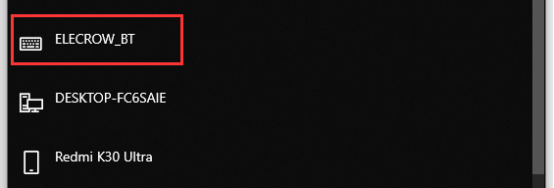
- Using a computer with wireless Bluetooth, turn on the Bluetooth device, click Add Bluetooth or other device,Select "ELECROW_BT" and connect.
- USB wired keyboard connection mode demo:
The example program defaults to "FN+4" key combination for switching to USB wired connection keyboard mode, after pressing the key combination, the "CABLE" indicator light is solid for 3S, and then off, then it can be operated directly using the Mechanical_Keyboard_ESP32-S3 keyboard.

- RGB equivalent switching demo:
By default, the sample program uses the "FN+Insert" key combination to switch different lighting effects.

FAQS
You can list you question here or contact with techsupport@elecrow.com for technology support.

