4.3inch ESP32-S3 Touch Display | 480*272 | Resisitive Touch | With WiFi and BLE

Description of Hardware Interface Functions

Interface Function Description
| Interface | Function Description |
|---|---|
| ① ESP32-S3 | The main controller of the display module, managing both on-board and external peripherals. |
| ② MicroSDCard Slot | Insert a MicroSD card to expand storage capacity for large data files such as font libraries, images, and audio files. |
| ③ Serial Port | 1.25mm 4-pin female connector. Used for serial debugging, programming, and communication. |
| ④ BOOT Button | Used to enter programming mode or for button testing. Hold this button down while powering on, then release to enter download mode. Alternatively, after powering on, hold this button down, press the RESET button, release the RESET button, and then release this button to enter download mode. When download mode is not required, this button functions as a standard button. |
| ⑤ TYPE-CPort | Used for module power supply and program downloading. This port is connected to the module’s one-button download circuit, enabling automatic entry into download mode (without pressing the BOOT button). |
| ⑥ RESET Button | Used to reset the ESP32 controller and LCD; pressing it resets the logic levels. |
| ⑦ Expansion Input Pins | 1.25mm 4-pin header. Exposes GPIO17/18 pins |
| ⑧ UART1 and USB Interface | 1.25mm 4-pin header. Exposes four unused pins: GPIO17, GPIO18, GPIO19, and GPIO20. GPIO17 and GPIO18 can be used for UART1, while GPIO19 and GPIO20 can be used for the USB protocol. |
| ⑨ SPI Peripheral Interface | 1.25mm 4-pin header. Used to connect external SPI devices; this SPI interface is shared with the resistive touchscreen and SD card. Can also be used as a standard I/O pin. |
ESP32 Pin Assignment
| On-board Devices | ESP32 Connection Pins | On-board Device Pin Descriptions |
|---|---|---|
| LCD | IO40 | LCD chip select control signal, active low |
| IO46 | Data enable control pin | |
| IO41 | Vertical sync signal control pin | |
| IO39 | Horizontal sync signal control pin | |
| IO42 | Pixel clock control pin | |
| IO42/48/47/21/14 | 5-bit RED data pins | |
| IO⅚/7/15/16/4 | 6-bit GREEN data pins | |
| IO8/3/46/9/1 | 5-bit BLUE data pins | |
| Resistive Touchscreen | IO12 | Resistive touchscreen SPI bus clock control pin |
| IO13 | Resistive touchscreen SPI bus data write control pin | |
| IO11 | Resistive touchscreen SPI bus data read control pin | |
| IO38 | Resistive touchscreen SPI bus chip select control pin | |
| IO18 | Resistive touchscreen SPI bus interrupt control pin | |
| MicroSD Card | IO10 | SD card SPI bus chip select control pin |
| IO11 | SD card SPI bus data read control pin | |
| IO13 | SD card SPI bus data write control pin | |
| IO12 | SD card SPI bus clock control pin | |
| Button | IO0 | Download mode selection button (press and hold this button while powering on, then release to enter download mode) |
| EN | ESP32-S3 reset button, low-level reset (shared with LCD reset) | |
| Serial Port | RXD0(IO43) | ESP32-S3 serial receive signal (can be used as a standard I/O pin if the serial port is not in use) |
| TXD0(IO44) | ESP32-S3 serial transmit signal (can be used as a general-purpose I/O pin if the serial port is not in use) | |
| SPI Interface | IO19 | SPI bus chip select control pin; can be used as a general-purpose I/O pin when the USB signal function is not in use |
| IO11 | SPI bus data read control pin; can be used as a general-purpose I/O pin when the SD card function is not in use | |
| IO13 | SPI bus data write control pin; can be used as a general-purpose I/O pin when the SD card function is not in use | |
| IO12 | SPI bus clock control pin; can be used as a general-purpose I/O pin when the SD card function is not in use | |
| Expansion Interface | IO18 | Can be used as a general-purpose I/O pin when the touch and SD card functions are not in use |
| IO17 | Can be used as a standard I/O pin when the touch and SD card functions are not in use | |
| USB | IO19 | USB bus differential signal data line (negative) |
| IO20 | USB bus differential signal data line (positive) | |
| UART1 | IO17 | ESP32-S3 UART1 transmit signal pin |
| IO18 | ESP32-S3 UART1 receive signal pin |
Get Started with Arduino IDE
Please click the card below to learn how to install Arduino IDE, and install ESP32 board in the Arduino IDE.

Note: ESP32 version 3.0 is based on ESP32 IDF 5.1, while version 2.0 is based on ESP32 IDF 4.4. The two versions have differences in their software APIs for Bluetooth, timers, I2S drivers, LEDC drivers, and other features. Therefore, if you compile the version 2.0 examples using version 3.0, errors will occur. Please pay attention to the version selection. The installation may take a long time, and download failures may occur during the process; you may need to try installing it several times. The downloaded installation package is saved in the “C:\Users\Administrator\AppData\Local\rduinol5\staging\packages” directory(where “Administrator” is the actual username of your computer; the ‘AppData’ directory is hidden. To access it, go to the Folder menu, select Tools > Folder Options, check “Show hidden files, folders, and drives,” and click OK to save the settings).
The download settings are as follows:
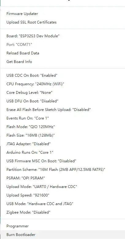
Here are the configuration parameters:
Port: Select the serial port to which the ESP32 development board is connected. Usually, it is automatically detected.
USB CDC On Boot: Enable switch for USB virtual serial port (USB-Serial-JTAG mode) output. Select "Enabled" to enable the serial port function, or "Disabled" to disable it. If your development board does not have a USB-to-serial function, it is recommended to enable this feature.
Note: USB virtual serial port is only supported on Windows 10 and later.
CPU Frequency: CPU clock frequency. Options: 240MHz (WiFi), 160MHz (WiFi), 80MHz (WiFi), 40MHz, 20MHz, 10MHz. Generally, higher frequency consumes more power. Choose according to your needs. If power consumption is not a concern, select the maximum 240MHz for best performance. Note that 240MHz, 160MHz, and 80MHz ensure normal WiFi and BT operation; other frequencies may not guarantee WiFi/BT functionality, only basic CPU operations.
Core Debug Level: Arduino kernel debug log level, output via serial port. Options: None, Error, Warn, Info, Debug, Verbose.
- None: No debug logs output.
- Error: Only error-level logs.
- Warn: Only warning and above.
- Info: Only info and above.
- Debug: Only debug and above.
- Verbose: All kernel debug logs.
Generally, you don’t need to pay attention to kernel debug logs unless developing kernel-related features. So select "None".
USB DFU On Boot: Configure whether to upgrade device firmware via USB during boot. Select "Enabled" (requires "USB-OTG" mode) or "Disabled" to turn off.
Erase All Flash Before Sketch Upload: Configure whether to fully erase the entire Flash before uploading code. Options: Disabled, Enabled. Select "Disabled" to avoid full erasure (faster upload and longer Flash lifespan). Select "Enabled" for full erase (slower upload and reduces Flash lifespan). So choose "Disabled".
Event Runs On: Configure which ESP32 core runs Arduino interrupt events. Options: Core0, Core1. Choose according to your needs. Default is Core1.
This can be the same as or different from ArduinoRunsOn. Same core reduces power consumption; different cores improve program efficiency.
Flash Mode: Communication mode and frequency of the Flash mounted on the ESP32. Options: QIO 80MHz, QIO 120MHz, DIO 80MHz, OPI 80MHz.
- QIO: uses 4 SPI data lines for Flash write/read.
- DIO: uses 2 SPI data lines.
- OPI: uses 8 SPI data lines.
Choose based on actual Flash connection. Here we use 4 lines, so select "QIO".
Flash Size: Capacity of the Flash mounted on the ESP32. Options: 4MB (32Mb), 8MB (64Mb), 16MB (128Mb), 32MB (256Mb). Choose according to actual capacity. Here the Flash is 16MB, so select "16MB (32Mb)".
JTAG Adapter: Configure JTAG adapter. Options: Disabled, integrated USB JTAG, FTDI Adapter, ESP USB Bridge. Using JTAG makes debugging easier. Choose as needed. Default is "Disabled".
Arduino Runs On: Configure which ESP32 core runs Arduino Core task code. Options: Core0, Core1. ESP32 has two cores (Core0 and Core1), each can run different tasks. Choose as needed. Default is Core1.
USB Firmware SVC On Boot: Configure another USB firmware upgrade method. When enabled, a removable storage drive appears on your computer, and you can drag firmware directly to it for upgrade. Select "Enabled" (requires "USB-OTG" mode) or "Disabled".
Partition Scheme: Flash space partitioning method on the ESP32. Arduino IDE provides dozens of schemes. Here, with 16MB Flash, generally choose "16MB flash (2MB APP/12.5MB FATFS)". If your project has many files and the compiled binary is large, you can choose "16MB flash (3MB APP/9.9MB FATFS)".
PSRAM: Configure external PSRAM on the ESP32. Options: Disabled, QSPI PSRAM, OPI PSRAM. Some ESP32 boards have external PSRAM for memory expansion; select accordingly. If only internal SRAM is present, select "Disabled". Here the ESP32 has 8-line PSRAM, so choose "OPI PSRAM".
Upload Mode: Configure code upload interface. Options: UART0/Hardware CDC, USB-OTG CDC (TinyUSB).
- UART0/Hardware CDC: use onboard USB-to-serial or USB virtual serial port to upload code.
- USB-OTG CDC (TinyUSB): use software-emulated USB hardware interface to upload code.
Here we use USB virtual serial port, so select "UART0/Hardware CDC".
Upload Speed: Code upload speed. Options: 51200, 230400, 256000, 115200, 921600. Choose based on the maximum speed supported by the onboard USB-to-serial chip. For example, the CH340C used here supports up to 2Mbps, so select the maximum 921600.
USB Mode: Configure USB interface mode. Options: Hardware CDC and JTAG, USB-OTG (TinyUSB).
- Hardware CDC and JTAG: use USB virtual serial port and JTAG debugging.
- USB-OTG (TinyUSB): use software-emulated USB hardware interface. This mode only needs to be configured when using USB OTG mode.
Note: When using USB Mode, you must connect to the device’s built-in USB interface, not the onboard USB-to-serial port.
Zigbee Mode: Configure Zigbee operation mode. Options: Disabled, Zigbee ZCZR.
- Disabled: turn off Zigbee function.
- Zigbee ZCZR: enable Zigbee function.
Zigbee is not used here, so select "Disabled".
Resources
This link contains all the information related to the screen, including various manuals, schematics, diagrams, sample programs, and more.
Where to Buy
Please visit this page to purchase 4.3inch ESP32-S3 Touch Display.
Support
If you encounter any issues while using the service, you can contact us via the social media links in the bottom-right corner of elecrow or send an email to techsupport@elecrow.com for technical support.