Binocular Stereo Vision Expansion Board for Raspberry Pi
Introduction
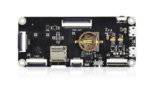
This binocular stereo vision expansion board is specially designed for Raspberry Pi Compute Module, compatible with CM3 / CM3 Lite / CM3+ / CM3+ Lite. Small in size but powerful in function. It features three CSI camera ports that can be connected by camera with different viewing angles or baseline value. It is flexible to build different Raspberry Pi stereo vision projects such as binocular parallax ranging, facial recognition, vivo detection, VR video recording and so on. Also, it has some common used ports like DSI and USB, it is convenient to be connected to LCD display and burning mirror directly. Moreover, it has peripheral interfaces like 24PIN HDMI and 36PIN GPIO are also supported through the FPC connector.
Model: RPA20901S
Features
- Comes with three camera ports
- DSI port allows directly connecting with DSI display
- With USB connector, convenient for burning mirror
- 36PIN GPIO connector for extending UART port and Raspberry Pi GPIO
- 24PIN HDMI extended connector for connecting with HDMI display
- 10PIN GPIO/I2C extended connector for connecting ICM20948 IMU fill light board
- Integrates DS1307 RTC chip and comes with CR1220 battery holder
- Comes with acrylic mounting plate and tripod adapter
- Compatible with Raspberry Pi Compute Module CM3 / CM3 Lite / CM3+ / CM3+ Lite compatibly
Usager
-
1. Burn image
-
1.1 Flash the image to Compute Module 3/Compute Module 3+
If you are using Raspberry Pi Compute Module 3 or Compute Module 3+. For these computing modules with eMMC, you need to burn the image to the eMMC on the computing module when using them, otherwise they cannot be used.
The steps to burn to eMMC are as follows:
1) Run RPiboot_Setup software on the computer and install the Raspberry Pi USB driver. It is recommended to turn off the anti-virus software before installation. After the installation is successful, there will be a rpiboot.exe software in the start folder, as shown in the following figure:
2) Switch the USB SLAVE ENABLE switch on the STEREO expansion board to the EN end
3) Connect the computing module (computing module with eMMC)
4) Connect the USB interface on the STEREO expansion board to the PC via a USB cable
5) At this time, open the software rpiboot.exe with administrator authority , and the PC will automatically recognize the eMMC in the computing module as a U disk.
6) Run Win32DiskImager-burn Record the image software , select the image, and burn the image to the eMMC.
Note: If the image has been burned before, you can use the Panasonic_SDFormatter-SD card formatting software to format it before burning.
7) After programming is complete, disconnect the USB cable. After disconnecting the power supply, reconnect the power supply to the PWR interface of the STEREO expansion board to start the system from eMMC.
- Note
-
During the programming process, the PC should not read and write other USB devices to avoid conflicts;
-
The official image provided by Raspberry Pi, the default account is: pi and the password is: Raspberry.
-
Since the eMMC of CM3 is only 4G (the latest CM3+ has expanded the capacity of eMMC and can support normal Raspberry Pi mirroring), the size of the burned image cannot exceed 4G. Therefore, if you burn Raspbian, you can only use the Lite version of the mirror. If you want a GUI. You can install the GUI by running the following command after the installation is complete:
If you can’t program normally with the STEREO expansion board, please try the following steps:
-
Use WIN10 system to burn, most customers feedback that WIN7 or linux system is unstable.
-
Make sure your CM3/CM3+ version is normal, there will be an additional IC on the back of eMMC. Only the eMMC version can be burned in the current way. For those without eMMC, please refer to "Flashing Image to Compute Module 3 Lite or Compute Module 3+ Lite".
-
Note that the PWR interface needs to be connected to a 5V power adapter.
-
Replace a USB data cable.
-
Replace the USB interface of a PC.
-
Try to restart the PC.
-
Try to unplug and plug CM3/CM3+ again.
-
Try to burn on another computer.
-
1.2 Flash the image to Compute Module 3 Lite or Compute Module 3+ Lite
The operation of flashing the image to Lite is:
1) Download the image that seems to be flashing.
2) Insert the TF card with a card reader into the computer. The minimum requirement for the TF card is 8G (16G or 32G is recommended).
3) Open Win32DiskImager-burning image software, and select the image burning prepared in step 1. (Same as burning the Raspberry Pi image)
4) After the burning is successful, insert the TF card into the TF card slot of the STEREO expansion board and power on.
- 2. Connect to DSI screen
The DSI screen model used in this experiment is: 4.3inch DSI LCD, or the Raspberry Pi screen provided by the Raspberry Pi Foundation
1) Make sure to operate under power off
2) Connect the 15Pin FPC cable to the DISP1 interface of the STEREO expansion board and the DSI screen
3) Connect power
4) Wait a few seconds before the screen starts
- Note:
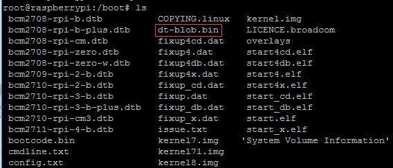
If you use the official image, you need to copy dt-blob.bin to the /boot directory to use it normally
Device tree source file and its binary file
- 3. Connect HDMI screen
The HDMI screen model used in this experiment is: 7 inch HDMI screen: ESP01215E
1) Remove the DSI screen, connect the HDMI adapter board to the HDMI interface of STEREO
2) Connect the HDMI screen, (if the HDMI screen Connect with the DSI screen, then the Raspberry Pi will only drive the DSI screen)
3) Change the config.txt file in the TF card to modify the resolution. For the screen model used this time, 7inch HDMI LCD (H) (with case) , Need to add the following statement at the end of config.txt:
max_usb_current = 1
  hdmi_force_hotplug = 1
  config_hdmi_boost = 10
  hdmi_group = 2
  hdmi_mode = 87
  hdmi_cvt 1024 600 60 6 0 0 0
4) After the change, restart the Raspberry Pi to drive the HDMI screen.
- 4. Connect CSI camera
4.1 Test the Raspberry Pi camera
The method to test the Raspberry Pi camera is:
1) Make sure that the mirror is downloaded from the Micro Snow Encyclopedia, the device tree is configured for the mirror, and the two cameras can be driven by commands without modification.
2)Connect the camera to the CAM0 and CAM1 interfaces. The CSI camera model used in this experiment is: IMX219-77 Camera.
3)After connecting, power on, after power on, you can check the camera effect:
View the first camera screen connected:
View the second camera screen connected:
The -cs parameter indicates the number of cameras that are connected, but the camera number indicated by the -cs parameter is not exactly the same as the silkscreen of the board and the shell (the parameter -cs indicates the number of cameras that are connected, if only it is connected If a camera is connected to the CAM1 interface, check that the -cs parameter of the camera command is 0 to indicate the 0th camera connected).
4.2 Source image, modify the device tree to drive the camera
If you use the image provided by us, the device tree has already been configured. This step can be skipped directly. If you are using a brand new image provided by the official, you need to reconfigure the device tree.
1)Run raspi-config, select Interfacing Options->Camera->Yes->Finish-Yes, reboot the system, and turn on enable camera.
2)The device tree file download official, the Raspberry Pi Foundation device tree referral link , Raspberry Pi Foundation device tree download 1 link , download link 2
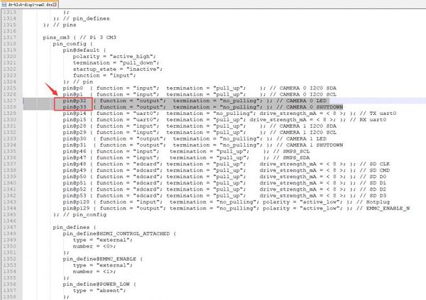
3)After downloading the device tree file, next, you need to modify the device tree file. The specific device tree is modified as follows:
Namely: Compared with the official device tree file, the specific modification is: the LDE and SHUTDOWN of Camera0 are changed from the original 4,5 pins to 32,33 pins.
4)After modifying the device tree file, compile the device tree file, the compilation method is as follows:
5)After compilation, a dt-blob.bin file will be generated. Just copy (replace) this file directly to the boot directory.
6)Restart, you can test the dual camera with the following command:
How to use CAM3 interface The CAM3 interface and the CAM1 interface are switched through the GPIO38 pin. If the GPIO38 interface is set to high level, the CS1 interface calls the camera of the CAM3 interface. If the GPIO38 interface is set to low level, the CS1 interface calls the camera of the CAM1 interface.
7) Run the following program
/CAM3_CAM1_Switch.sh 1 Switch to use CAM3 interface
8) Run the camera command test after switching
- 5. Test ICM20948
1) First download the sample program
2) Connect the ICM20948 fill light board to the STEREO expansion board through a 10pin cable
3)Turn on the I2C interface
Select Interfacing Options -> I2C -> Yes->OK
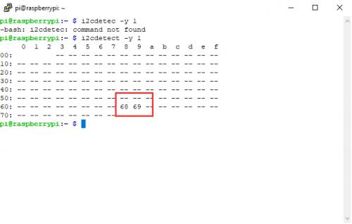
4) Check the I2c address
Two addresses of 68 69 can be detected, indicating that the module is connected normally Where 68 is the address of the RTC, 69 is the address of the ICM20948 chip
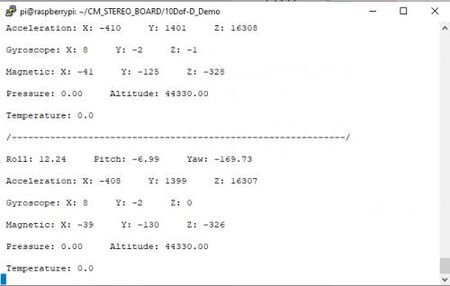
5) Run the following command to test ICM20948
After running the program, the terminal interface will print the information of the ICM20948 chip
Ctrl+c can close the program
- 6. Test RTC
1)The STEREO expansion board has a RTC spare battery holder, you can connect to the CR1220 button battery, the battery needs to be purchased separately
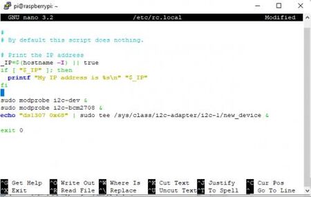
2)Modify the rc.local file
Add the following statement to the front of exit0
sudo modprobe i2c - dev &
sudo modprobe i2c - bcm2708 &
echo "ds1307 0x68" | sudo tee / sys / class / i2c - adapter / i2c - 1 / new_device &
3) Reboot the system
4) After restarting, check the I2c address again, and you will find that the original address 68 has become UU, which is normal
5)Read RTC time
After the command is executed, the current network time will be printed out. If the time is not correct, set the time zone in the system and test again.
6)You can also write the RTC time into the system
- 7. Test fill light and buttons
On the ICM20948 board, there are two fill lights onboard, one is white fill light and the other is infrared fill light. Here we combine the buttons on the STEREO board to test the fill light function
1)Run command
After successfully running the program, the infrared fill light will light up, press the button to switch between the infrared fill light and the white fill light Note that the brightness of the white fill light is relatively high. When testing, cover it to avoid direct exposure to the eyes.
Ctrl+C can terminate the program.
- 8. Test the serial port expansion board
1)Connect the serial port expansion board to the STEREO board through the 36PIN cable
2)Connect the USB port on the serial port expansion board to the computer with a USB cable
3)The Raspberry Pi system enables the serial port debugging interface function
Select Interfacing Options -> Serial -> Yes -> No -> OK
4)Restart the system, then open the putty software on the computer and use the serial port to log in to the Raspberry Pi
