ThinkNode M7 LoRaWAN Wireless Communication Gateway , Support PoE Power, Powered By ESP32-S3 and LR1110
Model LML15607D
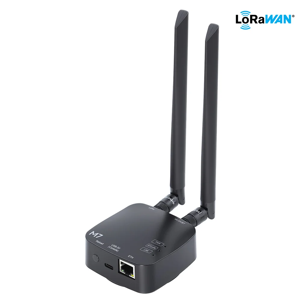
Introduction to the ThinkNode M7
The ThinkNode M7 is a compact single-channel LoRaWAN gateway designed for rapid deployment of indoor IoT applications. Powered by the ESP32-S3 dual-core processor and the Semtech LR1110 LoRa transceiver, it combines reliable LoRaWAN communication with Wi-Fi, Bluetooth® LE, and Ethernet connectivity in a single device. The gateway comes with pre-installed LoRaWAN packet forwarder firmware, allowing users to quickly connect end devices to The Things Stack (TTN) or other compatible LoRaWAN network servers with minimal configuration.
To simplify deployment, the ThinkNode M7 supports multiple network connection methods, including Wi-Fi and 100 Mbps Ethernet, with optional PoE power supply for flexible installation. The external high-gain antenna helps improve wireless coverage, while the compact enclosure makes the gateway suitable for offices, laboratories, classrooms, factories, and other indoor environments.
The LoRaWAN version of the ThinkNode M7 supports the major LoRaWAN regional frequency plans, including EU868, US915, and AU915. It is optimized for learning, prototyping, proof-of-concept projects, and small-scale private LoRaWAN deployments.
Next, we’ll take a look at how the ThinkNode M7 is used in practice.
Example: The LR1262 Node Board uploads data to TTN server via ThinkNode_M7
Communicate with the gateway through the created TTN application node and upload the node-gateway communication data to the TTN server
Prerequisites:
-
The gateway has been created in TTN, and the ThinkNode_M7 gateway has been connected and operated normally.
-
Node applications (OTAA/ABP) corresponding to the band range of the gateway have been created in TTN
hardware preparation:
①.LR1262 Node Board
②.PC and mobile phone
③.USB TYPE-C cable
④.ThinkNode_M7

Getting Started Quickly with the Gateway
1、 Power the gateway using a 5 V USB Type-C power supply.Connect the antenna that matches your operating frequency (868 MHz or 915 MHz).(The ThinkNode M7 is equipped with a universal antenna for the 868 and 915 bands.). The physical wiring diagram is as follows:

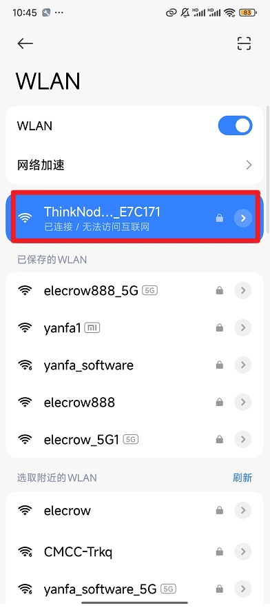
2、 Power on the gateway, press and hold the Reload button for 5 seconds, then release. The device will enter the gateway configuration mode, and the green LED(LINK) will blink, Use a computer or mobile phone to connect to the gateway's Wi-Fi network (ThinkNode-M7_xxxxxx),with the password: 88888888.
3、 Open a browser and enter 192.168.4.1 to access the gateway configuration page:
Wi-Fi Setup Steps:
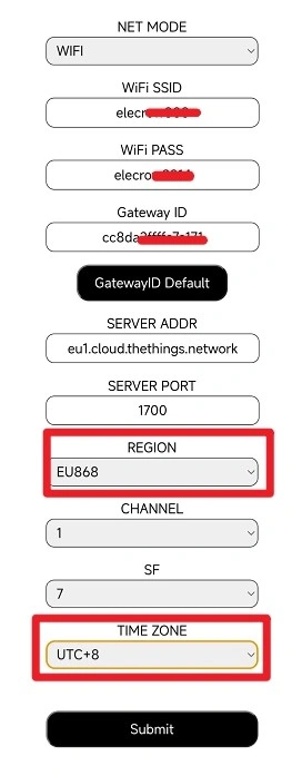
-
NET MODE:Wi-Fi
-
WIFl SSID: Enter the Wi-Fi name you want to connect to (non-5GHz Wi-Fi network)
-
WIF| PASS: Enter the password for the Wi-Fi network you want to connect to
-
Gateway lD: xxxxxxffffexxxxx(Gateway ID: Enter a unique Gateway ID. This ID is required when registering the gateway on TTN, so make sure to save it for later use.)
-
SERVER ADDR: eu1.cloud.thethings.network (default)
-
SERVER PORT:1700(default)
-
REGION: EU868/US915/AU915(Select according to the actual frequency band)
-
CHANNEL: (Choose according to the frequency of the connected device)(Default 0)
-
SF:(Choose according to the frequency of the connected device)(Select “12” for EU868MHz, ‘10’ for US915MHz, and “10” for AU915MHz.)
-
TIME ZONE: UTC(Select the utc time zone of your location)
After verifying that all settings are correct, click Submit to submit the configuration information. The gateway will restart automatically., after successful configuration. The green BT LED will remain solid.
Ethernet Setup Steps:

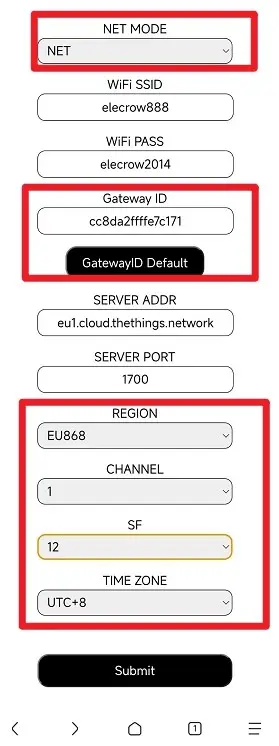
Open a browser and enter 192.168.4.1 to access the gateway configuration page:
-
NET MODE:NET
-
Gateway lD: xxxxxxffffexxxxx(Gateway ID: Enter a unique Gateway ID. This ID is required when registering the gateway on TTN, so make sure to save it for later use.)
-
SERVER ADDR: eu1.cloud.thethings.network (default)
-
SERVER PORT:1700(default)
-
REGION: EU868/US915/AU915(Select according to the actual frequency band)
-
CHANNEL: (Choose according to the frequency of the connected device)(Default 0)
-
SF:(Choose according to the frequency of the connected device)(Select “12” for EU868MHz, ‘10’ for US915MHz, and “10” for AU915MHz.)
-
TIME ZONE: UTC(Select the utc time zone of your location)
Connecting to the TTN
There are two ways to connect to the Things Network: the Packet Forwarder and the Basics™ Station. choose one of the ways to connect to the gateway. the ThinkNode gateway is configured with Packet Forwarder by default.
The Semtech UDP Packet Forwarder is the original LoRaWAN® Packet Forwarder, which connects to the server via the Semtech UDP protocol.
The LoRa Basics™ Station is the preferred way to connect the gateway to The Things Stack.
Connecting via Packet Forwarderer The Semtech UDP Packet Forwarderer is the original LoRaWAN® Packet Forwarderer that connects to the server via the Semtech UDP protocol.
TTN Configuration
Step 1: Log in to The Things Stack (console.cloud.thethings.network). If you do not have a TTN account, register first.

Step 2: Register the Gateway

Gateway EUI: The 64-bit Extended Unique Identifier of the gateway. The Gateway EUI is printed on the product label and is also available in the Web UI. Instructions on how to access the gateway through the Web UI can be found in the Quick Start Guide. As shown below, type Gateway EUI and click Confirm to continue.

Gateway ID: The Gateway ID may contain lowercase letters, numbers, and hyphens only.
Gateway Name: Enter a descriptive name for your gateway.
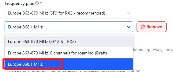
Frequency plan: Select the frequency plan that matches your gateway hardware version.

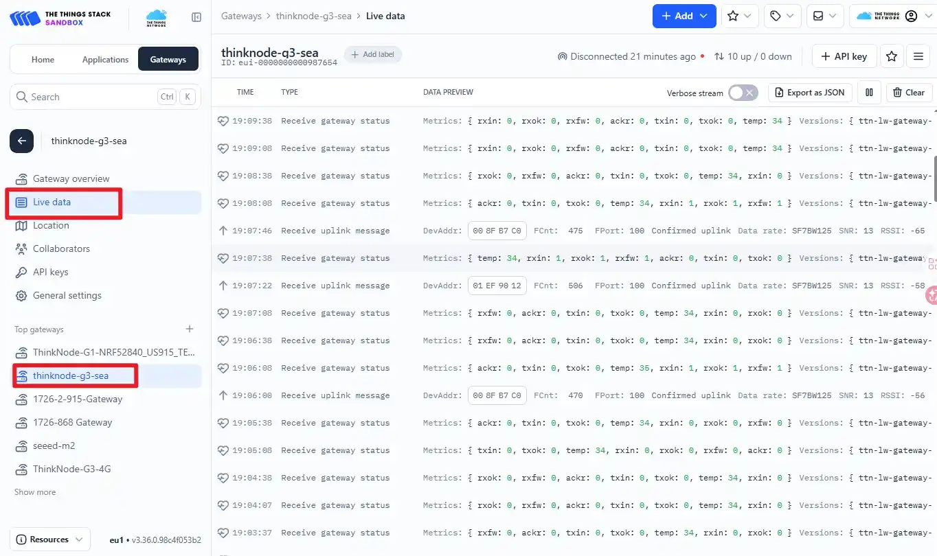
After successful registration, you can view the gateway in the overview.

Select the newly created gateway and click “Live Data” to view the connection status
Creating TTN Node Applications
Step 1: Log in to your registered TTN account, in the TTN server interface, click Applications.

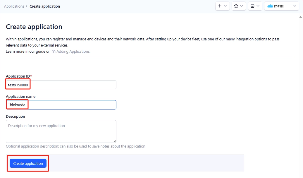
Step 2: Click Add applications, start to add node applications, enter the Applications ID, Applications name, and then click Create applications.
Step 3: Enter the application overview page, click “Register end device” in the lower right corner to register a new device in TTN platform.

Step 4: In the “Register end device” page, click Enter end device specifics manually option.

Step 5: Set the Frequency plan, LoRaWAN version and Regional Parameters version to JoinEUI (APPEUI).
Note: JoinEUI means AppEUI.
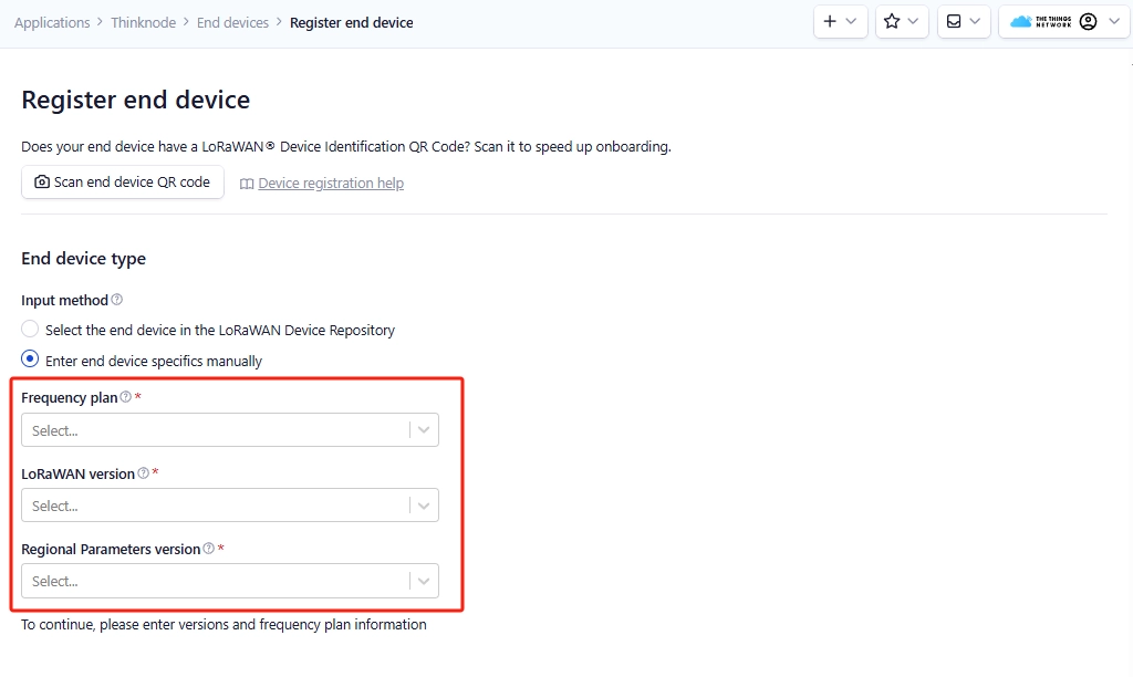
Set the Frequency plan,note that the band range should be consistent with the gateway used.

Set LoRaWAN version
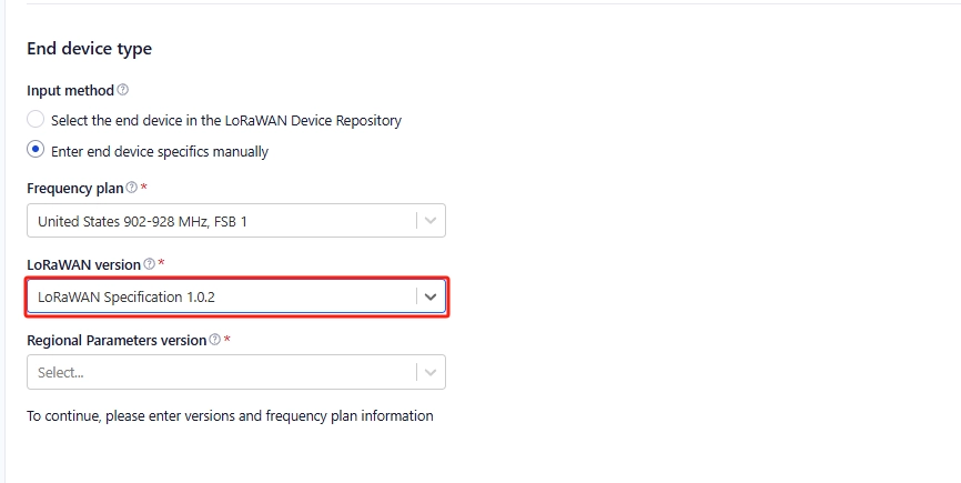
Set the Regional Parameters version

Set JoinEUI (APPEUI).

Step 6: Click Show advanced activation, LoRaWAN class and cluster settings. Configure parameters such as activation mode and device operating mode.
activation mode is OTAA when

Configure to OTAA mode (i.e., default mode)

Then click Confirm

when the activation mode is ABP

Step 7: Configure the corresponding device parameters according to the activation mode selected above, as shown in the following figure:
when the activation mode is OTAA
Click Generate,automatically generate DevEUI.

Click Generate to generate AppKey automatically.

Enter the End device ID

Click Register end device

OTAA device is successfully registered.

activation mode is ABP

Enter DevEUI

Click Generate to generate Device address automatically.

Click Generate to generate AppSkey automatically.

Click Generate to generate NwkSkey automatically.

Enter the end device ID.

Click Register end device

ABP device is successfully registered.

Settings for the LR1262 Node Board
software preparation
1.Configure LR1262 Node Board as USB-TTL communication software program “RP2040-USB-TTL.ino.rpipico.uf2”.
2.SSCOM serial port tool
Configure the LR1262 Node Board as USB-TTL communication mode (actually through the RP2040 comes with a USB interface, through the software program to realize the UART communication between the RP2040 and the LR1262).
Connect the LR1262 Node Board to the PC through the TYPE-C cable, and then first press the Connect the LR1262 Node Board with PC via TYPE-C cable, first press the “RP2040_BOOT” button on the LR1262 Node Board, and then press the ‘RST’ button, then a “RPI-XX” virtual USB flash disk will be popped up on the PC automatically. “Copy ”RP2040-USB-TTL.ino.rpipico.uf2“ to the ”RPI-XX" virtual USB flash disk and wait for the copying to complete. The LR1262 Node Board can be configured for USB-TTL communication.
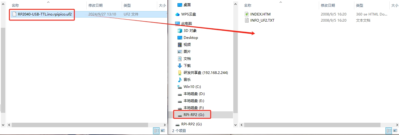
Note: After the program is burned, you need to power off the LR1262 Node Board, and then power on it again!
Through the SSCOM serial tool, send AT commands to configure the LR1262 Node Board as an OTAA/ABP node application established in the TTN, and through sending AT commands, join the LR1262 Node Board to the LoRaWAN network, complete the networking communication with the gateway, and upload the real-time node and gateway communication data between the node and the gateway is uploaded to the TTN server.
Use OTAA mode to join the LoRaWAN network (LR1262 Node Board uses the network entry mode by default)
Step 1: Open the SSCOM serial port tool in the Serial Port Assistant, select the USB COM port recognized by your computer, and then click “EXT”, as shown below.

Step 2: Select and input the AT command information as follows on the extended interface of the serial port assistant:
(1) Serial port setting
1, baud rate: 9600 baud
2, check the serial port carriage return line feed
(2) Node access to the single-channel gateway configuration steps (send AT commands)
1、AT + RFS: clear the flash memory, every time you set up the access frequency band or re-entry, you have to send this command to clear the flash memory of the internal chip of the LR1262, otherwise it will affect the module. This instruction must be sent to clear the flash memory of the internal chip of LR1262 every time before setting the access band or re-entering the network.
2、AT+RESET:LR1262 node module reset instruction, you need to reset LR1262 module before re-entering the network.
3、Select the node as single channel/multi-channel mode: AT+ChannelMode=0 (0 is single channel, 1 is multi-channel).
4、set the node into the network band: AT + BAND = 8, (5 for the 868 band, 8 for the 915 band, if it is a single-channel mode, the instruction is AT + BAND = 8,x (X for the selection of the band number 868 optional (0-2), 915 optional (0-7))).
5、Set node DevEui:AT+DevEui=70B3D57ED006**** (Red part corresponds to TTN server)
6、Set node AppEui:AT+AppEui=220033001100**** (Red part corresponds to TTN server)
7、Set node AppKey:AT+AppKey AppKey=F80013BC56A2B55375E467CBE5D9**** (the red part corresponds to the TTN server)

Here, it is important to note that DevEui, AppEui and AppKey should be replaced by DevEui, AppEui and AppKey in the application of the created OTAA node.

8、set the node to start netting: AT+JOIN=1,8 (parameter description: the first parameter is to select the netting mode, 0 is ABP mode, 1 is OTAA mode, the second parameter is the number of times to request netting cyclically in OTAA mode (1-8), ABP mode does not need to be cyclic). After sending this command, you need to wait for the node to enter the network, after the node enters the network successfully, then you can send the next command, as shown in the following figure: the information printed by the serial port tool after the successful entry:

Input the above AT commands in Serial Assistant Expansion Interface, when you input the command “AT+JOIN=1,8”, “joined successfully” will appear, which means the LR1262 node module has been joined successfully!
9、start to send data: AT + SEND = 1:0:2233 (parameters: the last parameter for the data to be sent, and can only send an even number of data) SSCOM Serial Assistant commands are shown below:
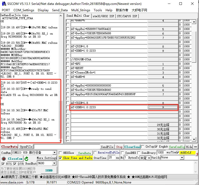
10、use “AT+SEND=1:0:2233” command to send data, in the background of the TTN server “Applications->Live data” you can see the node real-time sent data “2233”

Use ABP mode to join LoRaWAN network
Step 1: Open the SSCOM serial port tool in the serial port assistant, select the USB COM port recognized by the computer, and click “EXT”, as shown in the following figure:
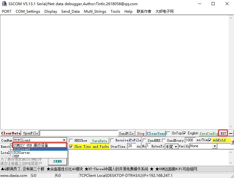
Step 2: Select and enter the AT command information as follows on the extended interface of the serial port assistant:
(1) Serial port setting
1, baud rate: 9600 baud
2, check the serial port carriage return line feed
(2) Node access to the single-channel gateway configuration steps (send AT commands)
1、AT + RFS: clear the flash memory, every time you set up the access frequency band or re-entry, you have to send this command to clear the flash memory of the internal chip of the LR1262, otherwise it will affect the module's performance. This instruction must be sent to clear the flash memory of the internal chip of LR1262 every time before setting the access band or re-entering the network.
2、AT+RESET:LR1262 node module reset instruction, you need to reset LR1262 module before re-entering the network.
3、Select the node as single channel/multi-channel mode: AT+ChannelMode=0 (0 is single channel, 1 is multi-channel).
4, set the node into the network band: AT + BAND = 8, (5 for the 868 band, 8 for the 915 band, if it is a single-channel mode, the instruction is AT + BAND = 8,x (X for the selection of the band number 868 optional (0-2), 915 optional (0-7))).
5、Set node DevEui:AT+DevEui=1A2A2A2A2A2C2C**** (Red part corresponds to TTN server)
6、Set node DevAddr:AT+DevAddr=2A2A22A2 (Red part corresponds to TTN server)
7、Set node NwkSKey:AT+NwkSKey= 25A252C25D2C2B6E2D3D3F2C2B3D**** (the red part corresponds to the TTN server)
8、Set the node AppSKey: AT+AppSKey=C2D2B2F2E3A2F1A35D1256216553**** (the red part corresponds to the TTN server)
Here, we should note that the Here, note that DevEui, DevAddr, NwkSKey, and AppSKey are replaced with DevEui, DevAddr, NwkSKey, and AppSKey in the application of the created ABP node.
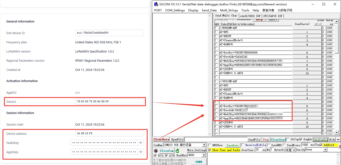
9、Set the node to start the network: AT + JOIN = 0 (parameter description: the first parameter is to select the network mode, 0 for ABP mode, 1 for OTAA mode, the second parameter is the number of times (1-8) of cyclic request to enter the network in the OTAA mode, no need to cycle in the ABP mode). After sending this command, you need to wait for the node to enter the network, after the node enters the network successfully, then you can send the next command, as shown in the following figure: the information printed by the serial port tool after the successful entry:

Input the above AT commands in Serial Assistant Expansion interface, when you input the command “AT+JOIN=0”, “joined successfully” will appear, which means the LR1262 node module has been joined successfully!
10、in ABP mode, before using AT+SEND instruction to send data, you need to set up the messaging of the ABP node that has just joined the network on the TTN server website.

In the Messaging interface, enter FPort as 1, select Confirmed downlink, and then click Schedule downlink.

11、use “AT+SEND=1:0:ABCD” command to send data, in the background of TTN server “Applications->Live data” you can see the real-time data sent by the node. “ABCD”.

How to buy
Please visit this page to purchase ThinkNode M7 LoRaWAN.
Support
If you encounter any issues while using the product, you can contact us via the social media links in the bottom-right corner of elecrow or send an email to techsupport@elecrow.com for technical support.