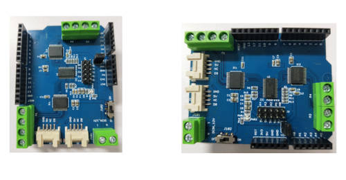
4 Channel I2C Motor Shield v1.1
Introduction
For Arduino beginners, there will always be problems when driving DC motors and servos. If you want to drive 4 motors and 2 servos, you need to build a platform to control their speed and direction of rotation. When the motor and steering gear are running, the current is large, and you will need a module to help you control the large current, such as a micro controller like Arduino.
Therefore, Elecrow has designed the driver board you need in this type of application. This module will help users solve the problem of high-current drive and control of the motor. You only need to plug it into the Arduino or Crowduino. This module is connected to the Arduino or Crowduino through the I2C bus. Start your application and you can control 4 channels through the I2C bus. Motor.
This driver board is designed based on the MOSFET H-bridge integrated circuit TB6612FNG, and its efficiency is higher than that of the transistor H-bridge driver. Compared with the L293D's average drive current of 600 mA per channel and 1.2 A pulse peak current, its output load capacity has doubled. Compared with the L298N's heat dissipation and peripheral diode freewheeling circuit, it does not require an external heat sink, and the peripheral circuit is simple. Only an external power supply filter capacitor can directly drive the motor, which is beneficial to reduce the system size. For the PWM signal, it supports frequencies up to 100 kHz, which also has greater advantages over the 5 kHz and 40 kHz of the above two chips.
- Motor Drive Control:
-
a. PCA9685 outputs PWM signals to control two TB6612FNG motor drive circuits, and then control 4 channels motors respectively;
-
b. Motor control mode: forward/reverse/brake/stop.
- Servo Control:
-
The servo plug is inserted into the socket on the 4 Channel I2C Motor Shield board, and the Arduino or Crowduino controls the servo to work through D8 and D9.
Model: ARS27361T
Features
- Logic control voltage: 2.7~5.5V
- Motor power supply voltage: 6~15V
- Single channel continuous drive output current: 1.2 A
- Starting peak drive current: 2A/3.2 A (continuous pulse/single pulse)
- Driving current Io: 2A
- Maximum power consumption: 18W
- Working temperature: -20 degrees Celsius to +85 degrees Celsius
- Drive type: dual high-power H-bridge drive
Specification
Interface Description
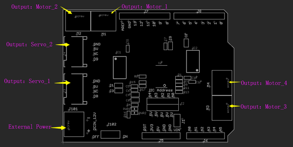
Motor power supply voltage: ------> External power supply, which may be 6~13.5V depending on the motor you use.
Power indicator: ------> LED indicator of external power supply.
Motor driver: ------> TB6612FNG high-power H-bridge driver.
Drive ports: ------> 4 motor ports and 2 servo ports.
Usage
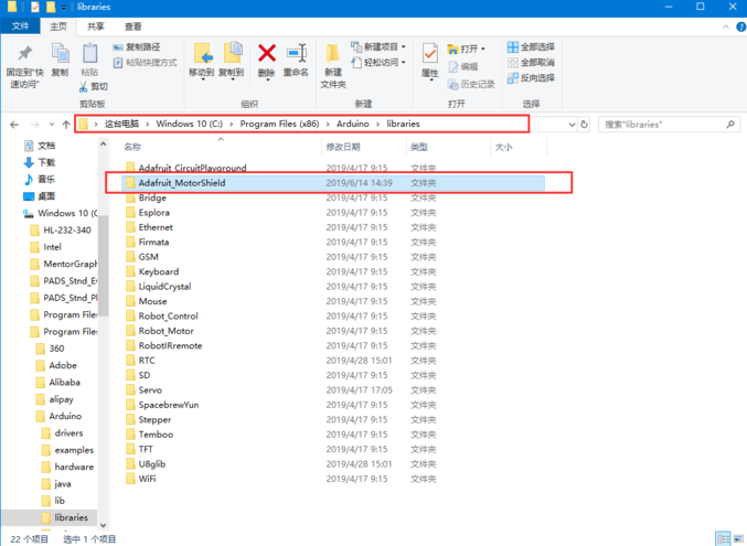
Copy the library file "Adafruit_MotorShield" in the "4 Channel I2C Motor Shield-V1.1-Example" folder to the library directory under the Arduino IDE installation directory. For example, our directory is: C:\Program Files (x86) \Arduino\libraries, as shown in the figure:
-
Motor control
-
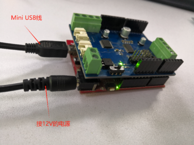
Insert the 4 Channel I2C Motor Shield-V1.1 board into the Arduino motherboard (Crowduino UNO motherboard), connect the DC interface of the Arduino motherboard to a 12V power supply, and connect the Mini USB data cable to the USB port of the Arduino motherboard, and then connect it On the computer, as shown in the figure:
-
Open the 4 Channel I2C Motor Shield-V1.1-Example\DCMotorTest\DCMotorTest.ino program and download it to the Arduino.
-
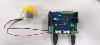
Then connect the micro motor to the M1, M2, M3, and M4 terminals on the 4 Channel I2C Motor Shield-V1.1 board (note: each operation must be powered off before connecting the motor), as shown in the figure, After connecting the motor, turn on the electricity and observe the phenomenon.
-
Observe that each interface motor accelerates forward for a few seconds and accelerates reverse for a few seconds, then the DC motor drives normally.
#include <Wire.h>
#include <Adafruit_MotorShield.h>
#include "utility/Adafruit_MS_PWMServoDriver.h"

// Create the motor shield object with the default I2C address
Adafruit_MotorShield AFMS = Adafruit_MotorShield(0x60);
// Or, create it with a different I2C address (say for stacking)
// Adafruit_MotorShield AFMS = Adafruit_MotorShield(0x61);

// Select which 'port' M1, M2, M3 or M4. In this case, M1
Adafruit_DCMotor *myMotor = AFMS.getMotor(1);
Adafruit_DCMotor *myMotor2 = AFMS.getMotor(2);
Adafruit_DCMotor *myMotor3 = AFMS.getMotor(3);
Adafruit_DCMotor *myMotor4 = AFMS.getMotor(4);

// You can also make another motor on port M2
//Adafruit_DCMotor *myOtherMotor = AFMS.getMotor(2);

void setup() {
  Serial.begin(9600);           // set up Serial library at 9600 bps
  Serial.println("Adafruit Motorshield v2 - DC Motor test!");

  AFMS.begin();  // create with the default frequency 1.6KHz
  //AFMS.begin(1000);  // OR with a different frequency, say 1KHz

  // Set the speed to start, from 0 (off) to 255 (max speed)
  myMotor->setSpeed(150);
  myMotor->run(FORWARD);
  // turn on motor
  myMotor->run(RELEASE);

  myMotor2->setSpeed(150);
  myMotor2->run(FORWARD);
  // turn on motor2
  myMotor2->run(RELEASE);

  myMotor3->setSpeed(150);
  myMotor3->run(FORWARD);
  // turn on motor3
  myMotor3->run(RELEASE);

  myMotor4->setSpeed(150);
  myMotor4->run(FORWARD);
  // turn on motor4
  myMotor4->run(RELEASE);
}

void loop() {
  uint8_t i;

  Serial.print("tick");

  myMotor->run(FORWARD);
  myMotor2->run(FORWARD);
    myMotor3->run(FORWARD);
    myMotor4->run(FORWARD);
  for (i=0; i<255; i++) {
    myMotor->setSpeed(i);
    myMotor2->setSpeed(i);
    myMotor3->setSpeed(i);
    myMotor4->setSpeed(i);
    delay(10);
  }
  for (i=255; i!=0; i--) {
    myMotor->setSpeed(i);
    myMotor2->setSpeed(i);
    myMotor3->setSpeed(i);
    myMotor4->setSpeed(i);
    delay(10);
  }

  Serial.print("tock");

  myMotor->run(BACKWARD);
  myMotor2->run(BACKWARD);
  myMotor3->run(BACKWARD);
  myMotor4->run(BACKWARD);
  for (i=0; i<255; i++) {
    myMotor->setSpeed(i);
    myMotor2->setSpeed(i);
    myMotor3->setSpeed(i);
    myMotor4->setSpeed(i);
    delay(10);
  }
  for (i=255; i!=0; i--) {
    myMotor->setSpeed(i);
    myMotor2->setSpeed(i);
    myMotor3->setSpeed(i);
    myMotor4->setSpeed(i);
    delay(10);
  }

  Serial.print("tech");
  myMotor->run(RELEASE);
  myMotor2->run(RELEASE);
  myMotor3->run(RELEASE);
  myMotor4->run(RELEASE);
  delay(1000);
}
-
-
Stepper control
-
Open the 4 Channel I2C Motor Shield-V1.1-Sample\servo\servo.ino program and download it to the Arduino.
-
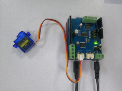
Connect the 9G servo to the J3 and J4 ports on the 4 Channel I2C Motor Shield-V1.1 board respectively, and observe the phenomenon, as shown in the figure:
-
Both interfaces observe the stepping motor's forward and reverse rotation, then the drive is normal.
#include <Servo.h>
Servo myservo;  // create servo object to control a servo
              // a maximum of eight servo objects can be created
Servo myservo1;

int pos = 0;    // variable to store the servo position

void setup()
{
  myservo.attach(9);  // attaches the servo on pin 9 to the servo object
  myservo1.attach(8);
}

void loop()
{
  for(pos = 0; pos < 180; pos += 1)   // goes from 0 degrees to 180 degrees
  {                             // in steps of 1 degree
    myservo.write(pos);            // tell servo to go to position in variable 'pos'
    myservo1.write(pos);
    delay(15);                    // waits 15ms for the servo to reach the position
  }
  for(pos = 180; pos>=1; pos-=1)     // goes from 180 degrees to 0 degrees
  {
    myservo.write(pos);            // tell servo to go to position in variable 'pos'
    myservo1.write(pos);
    delay(15);                    // waits 15ms for the servo to reach the position
  }
}
-
