Lora RA-08H Development Board
Description
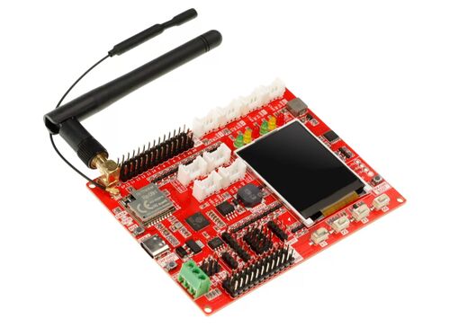
Lora RA-08H Development Board is a development board based on the combination of Raspberry Pi RP2040 main control chip and RA-08H, onboard TFT 1.8-inch SPI display, passive buzzer, RS485 communication module, customizable buttons, programmable indicator lights, multiple Crowtail and general IO interfaces, rich external interface resources, can be used with Crowtail series modules or modules with other interfaces. The onboard Lorawan module is connected to the Lorawan platform to realize remote module control, which can be applied to maker education, smart home, industrial control, etc.
Model: CRT01259B
Feature
- Integrate RP2040 and RA-08H (Lorawan module)
- Main control Raspberry Pi chip RP2040, built-in 264KB SRAM, onboard 4MB Flash
- Dual Core Arm Cortex-M0+ @ 133MHz
- RA-08H module adopts embedded memory, 128KB Flash, 16KB SRAM
- RA-08H module supports frequency band: 803MHZ-930MHZ
- RA-08H module supports external antenna, SMA interface or IPEX first generation interface
- Compatible with Arduino/Micropython
- Onboard 1.8-inch SPI-TFT-LCD, resolution: 128*160 driver chip: ST7735S (4-wire SPI)
- 1 passive buzzer
- 4 user-defined buttons
- 6 programmable LEDs
- 1 RS485 communication interface
- 8 5V Crowtail interfaces (2 analog interfaces, 2 digital interfaces, 2 UART interfaces, 2 IIC interfaces)
- 12 5V universal pin header IO interfaces
- 14 3.3V universal pin header IO interfaces
- 1 3.3V/5V switchable SPI interface
- 1 3.3V/5V switchable UART interface
- 3 3.3V/5V switchable IIC interfaces
Technical Specification
- Working input voltage: USB 5V-1A
- Operating temperature range: -10°C ~ 65°C
- Dimensions: 102mm(L)x76.5mm(W)
Interface Function
- Onboard Ports and Functions
| Name | Interface/Function Definition |
|---|---|
| DATA | RA-08H data sending and receiving indicator light, when RA-08H communicates with the outside world (need to be set by the user). |
| PWR | Power Indicator |
| RST | Reset button, press this button to reset the system. |
| (RP2040)BOOT | Download button, hold down the Boot button and press the RESET button to enter boot firmware download mode. Users can download firmware through the USB interface. |
| USB-C | USB-C interface, it is used for the power supply of the development board and the communication interface between PC and RP2040. |
| RS485 | RS485 interface, used to communicate with external RS485 module. |
| 485RX<-RX->RX1 | 3P pin header interface RS485 chip and RP2040 communication pin switching interface, when using the RS485 module, it is necessary to short the RX and 485RX with a jumper cap, when not using the RS485 module, the default is to short the RX and RX1. |
| 485TX<-TX->TX1 | 3P pin header interface RS485 chip and RP2040 communication pin switching interface, when using the RS485 module, it needs to short-circuit its TX and 485TX with a jumper cap, and when using the RS485 module, the default is to short-circuit the TX and TX1. |
| 3V3<-VCC->5V | 3P pin header interface, used for switching the working voltage of these three interfaces: 6P-SPI interface, 3*4P-IIC interface and 4P-UART interface. |
| SPI | 6P-SPI pin header interface, which can be used for external SPI interface communication modules and devices, and the power supply voltage is 3.3V/5V switchable. |
| I2C | 3*4P-IIC pin header interface, can be used for external I2C interface communication modules and devices, power supply voltage 3.3V/5V switchable. |
| UART | 4P-UART pin header interface, can be used for external UART serial communication modules and devices, power supply voltage 3.3V/5V switchable. |
| GND-5V-SIG | 3*12PIN, 5V general-purpose IO header interface, which can be used for external 5V sensor modules or devices. |
| GND-3V3-SIG | 3*14PIN, 3.3V general-purpose IO header interface, which can be used for external 3.3V sensor modules or devices. |
| Crowtail-A0 | External Crowtail-5V-HY-4P-2.0 port. Sensors or modules that can be used to interface with 5V Crowtail analog signals. |
| Crowtail-A1 | External Crowtail-5V-HY-4P-2.0 port. Sensors or modules that can be used to interface with 5V Crowtail analog signals. |
| Crowtail-D0 | External Crowtail-5V-HY-4P-2.0 port. Sensors or modules that can be used to interface with 5V Crowtail digital signals. |
| Crowtail-D1 | External Crowtail-5V-HY-4P-2.0 port. Sensors or modules that can be used to interface with 5V Crowtail digital signals. |
| Crowtail-UART | External Crowtail-5V-HY-4P-2.0 port. Sensors or modules that can be used to connect to 5V Crowtail UART serial communication. |
| Crowtail-I2C | External Crowtail-5V-HY-4P-2.0 port. Sensors or modules that can be used to connect to 5V Crowtail I2C interface communication. |
| (RA-08H)BOOT | Long press the download button before power-on. Connect the external USB-to-serial port module. Connect the cables to the external USB-to-serial port module according to (GND~GND, RA-3V~3.3V, RA-RX~TX, RA-TX~RX) and update the firmware of the RA-08H module through the TremoProgrammer_v0.8 software. |
| LCD | 1.8 inch SPI display |
- GPIO Pin Corresponding Port
| RP2040 | Lora RA-08H Development Board |
|---|---|
| GPIO0 | Crowtail-UART0-TX0 |
| GPIO1 | Crowtail-UART0-RX0 |
| GPIO2 | GPIO2 |
| GPIO3 | GPIO3 |
| GPIO4 | RA-08H-LPRXD |
| GPIO5 | RA-08H-TXD |
| GPIO6 | GPIO6 |
| GPIO7 | GPIO7 |
| GPIO8 | GPIO8/UART1-TX1/Crowtail-UART1-TX1/485TX |
| GPIO9 | GPIO9/UART1-RX1Crowtail-UART1-RX1/485RX |
| GPIO10 | GPIO10/SPI1-SCK |
| GPIO11 | GPIO11/SPI1-MOSI |
| GPIO12 | GPIO12/SPI1-MISO |
| GPIO13 | GPIO13/SPI1-CS |
| GPIO14 | GPIO14/ Crowtail-D0 |
| GPIO15 | GPIO15/ Crowtail-D1 |
| GPIO16 | LCD-DC |
| GPIO17 | LCD-CS |
| GPIO18 | LCD-SCK |
| GPIO19 | LCD-DIN |
| GPIO20 | I2C0-SDA0/Crowtail-I2C-SDA/PCA9555-SDA |
| GPIO21 | I2C0-SCL0/Crowtail-I2C-SCL/ PCA9555-SCL |
| GPIO22 | LCD-RST |
| GPIO23 | LCD-BLK |
| GPIO24 | 485-EN |
| GPIO25 | DATA |
| GPIO26 | A0/ Crowtail-A0 |
| GPIO27 | A1/ Crowtail-A1 |
| GPIO28 | BUZZER |
| GPIO29 | ADC-KEY |
Usage
1. Development Environment Construction
1.1 Directly visit the Arduino official website and download the Arduino development tools supported by the device. The link is as follows: https://www.arduino.cc/en/software.

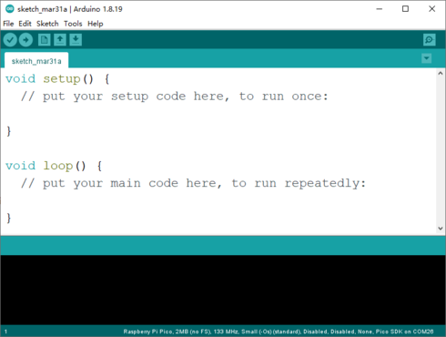
1.2 Click the downloaded Arduino development tool to install the software. After the software installation is complete, open it directly, as shown in the figure below:
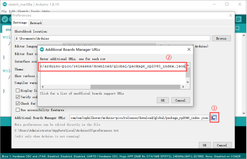
1.3 Click "File" -> "Preferences" on the menu bar to pop up the preference setting interface.

1.4 Click the icon on the far right of the Additional Boards Manager URLs column, enter https://github.com/earlephilhower/arduino-pico/releases/download/global/package_rp2040_index.json in the pop-up window, and add RP2040 Arduino IDE development board URLs.
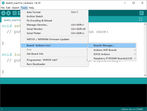
1.5 Click "Tools" -> "Board:..." -> "Boards Manager..." in the menu bar to enter the Boards Manager interface.
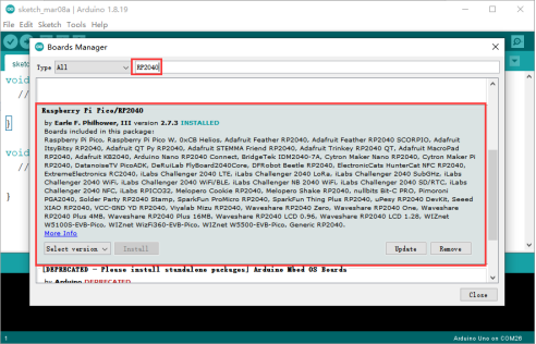
1.6 Enter "RP2040" in the search box, select "Raspberry Pi Pico/RP2040" and install the development environment.
It should be noted here that when selecting the development environment version, do not choose the latest one. It is recommended to choose version 2.6.0.
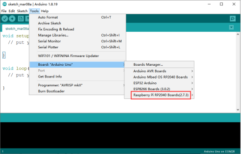
1.7 After the environment is successfully installed, if you find "Rasperry Pi RP2040 Boards" in the Arduino IDE development board management, it means that the environment is successfully built.
2. Software Settings
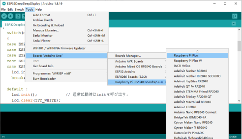
2.1 For the first use, you need to set up and select the correct development board. Click "Tools" -> "Board:..." -> "Rasperry Pi RP2040 Boards" -> "Rasperry Pi Pico" in the menu bar, as shown in the figure below:
2.2 Connect the Lora RA-08H Development Board to the computer via a TYPE-C USB cable. When the development board is connected to the computer for the first time, a "RPI-RP2" USB virtual U disk will appear.

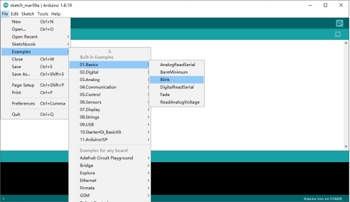
2.3 Here you need to burn a sample code in the opened Arduino IDE to convert the "RPI-RP2" USB virtual U disk into a "COM port". The sample code path is shown in the figure below:
The code after opening is as follows:
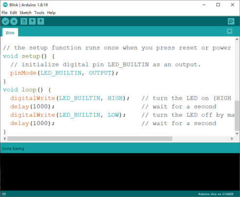
2.4 Click the download icon at the bottom of the menu bar to burn the code to the Lora RA-08H Development Board. After the code is burned successfully, COMXX (Raspberry Pi Pico) will be displayed in "Tools" -> "Port". Now you can program Lora RA-08H Development Board with Arduino IDE!
3. Sample Program
Example 1 - Driving the Onboard Passive Buzzer Let the buzzer go off!
3.1.1 The position of the onboard buzzer on the development board.
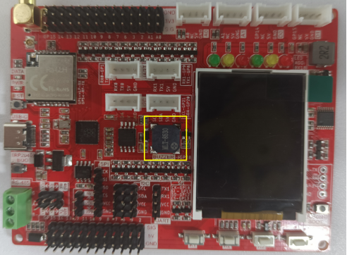
3.1.2 Open the "Buzzer.ino" sample program in the Arduino IDE, and then click the upload program icon to upload the program to the development board.

3.1.3 After the program is uploaded successfully, the buzzer will sound automatically!
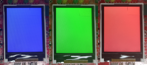
Example 2 - Let the onboard 1.8-inch LCD display red, green and blue respectively
3.2.1 Copy the "Adafruit-GFX-Library" library file and "Adafruit-ST7735-Library-master" library file to the libraries folder of the Arduino IDE.
( Original path: *"...\Lora_RA-08H_Development_Board\Library\..."; Copy path: **"...\Arduino\libraries\..." )*

3.2.2 Open the "LCD.ino" sample program in the Arduino IDE, and then click the upload program icon to upload the program to the development board.
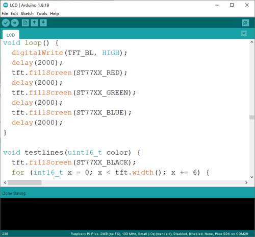
3.2.3 After the upload is successful, the LCD screen will display blue, green and red backlight in turn.
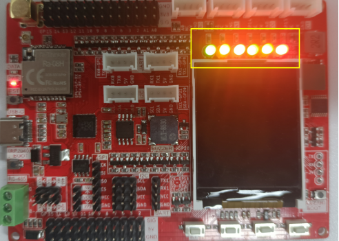
Example 3 - Light up 6 programmable LEDs on board through I2C control
3.3.1 Copy the "PCA9557" library file to the libraries folder of the Arduino IDE.

3.3.2 Open the "PCA9557_test.ino" sample program in the Arduino IDE, and then click the upload program icon to upload the program to the development board.

3.3.3 The effect after the program is uploaded successfully.
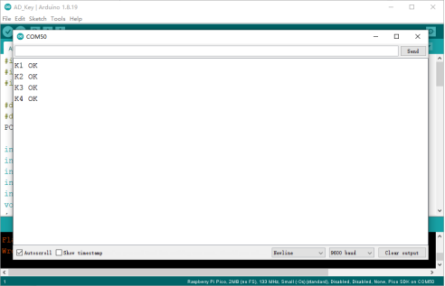
Example 4 - Read the 4 ADC-KEYs on the board through the ADC, and print the corresponding key value in the COM port
3.4.1 Open the "AD_Key.ino" sample program in the Arduino IDE, and then click the upload program icon to upload the program to the development board.
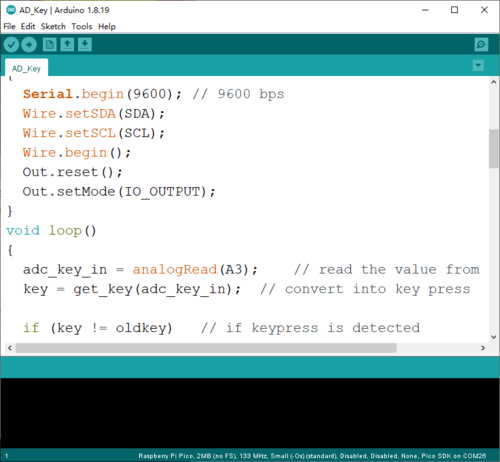
3.4.2 After the program is uploaded successfully, open the Serial Monitor. After pressing the keys one by one, observe whether the serial port prints the corresponding key value.

Example 5 - Light up 6 programmable LEDs on board through I2C control
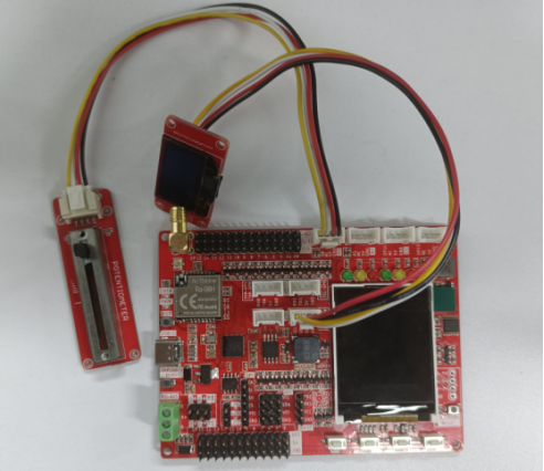
3.5.1 As shown in the figure below, connect the Crowtail OLED module and the Crowtail Potentiometer module to the Crowtail I2C interface of the Lora RA-08H Development Board.
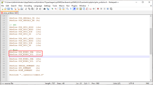
3.5.2 Find the Pins arduino.h file under the "... \Users \Administrator \AppData \Local \Arduino15\packages\rp2040\hardware\rp2040\2.0.0\variants\rpipico\..." path.
Opening the file, and modify the default definition "define PIN_WIRE0_SDA (4u)" and "define PIN_WIRE0_SDA (5u)" to "define PIN_WIRE0_SDA (20u)" and "define PIN_WIRE0_SDA (21)".
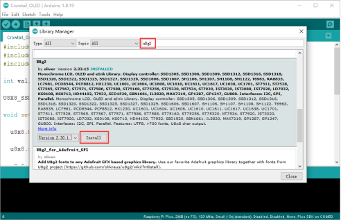
3.5.3 Install u8g2 library in Arduino IDE. Click "Sketch" -> "Include Library" -> "Manage Libraries", then enter "u8g2" in the pop-up interface, find "u8g2" and click "Install" to complete the installation of the u8g2 library.
3.5.4 Open the "Crowtail_OLED.ino" sample program in the Arduino IDE, and then click the upload program icon to upload the program to the development board.
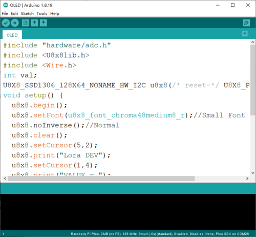
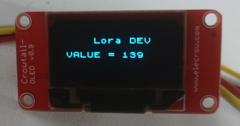
3.5.5 After power on, the value on the sliding potentiometer will be displayed on the OLED screen.
Example 6 - Communication between RP2040 and RA-08H
3.6.1 Open the "RA_08H.ino" sample program in the Arduino IDE, and then click the upload program icon to upload the program to the development board.
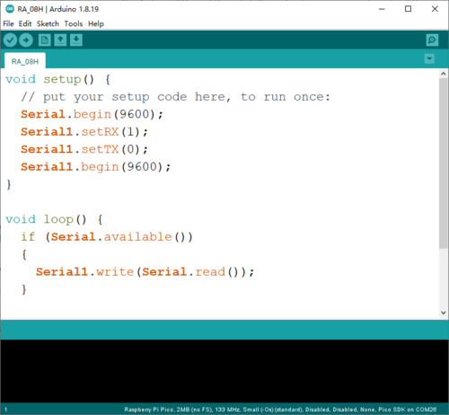
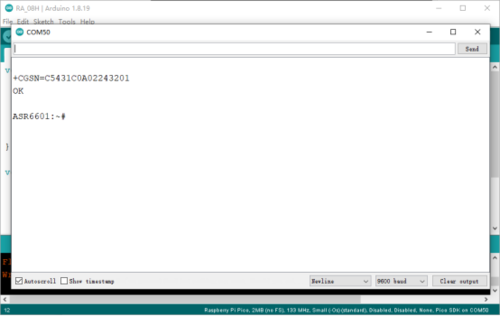
3.6.2 After the program is successfully uploaded, open the serial monitor and send the AT command "AT+CGSN?" to RA_08H.
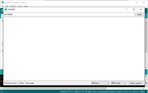
3.6.3 After sending the command, if the monitor can display the returned "+CGSN=85521C0A02243201 OK" (the value returned by different RA-08H firmware is different), it proves that you can send AT commands through the Arduino IDE to control and set the RA_08H module.
