TCS3200 Colour Sensor Module
Description
TCS3200 chip is designed to detect the color of light incident on it. It has an array of photodiode (a matrix of 8x8, so a total 64 sensors). These photodiodes are covered with four type of filters. Sixteen sensor have RED filter over them thus can measure only the component of red in the incident light. Like wise other sixteen have GREEN filter and sixteen have BLUE filter. As you should know that any visible colour can be broken into three primary colours. So these three type of filtered sensors helps measure the weightage of each of primary colours in incident light. The rest 16 sensors have clear filter.
TCS3200 converts the intensity of incident radiation into frequency. The output waveform is a 50% duty cycle square wave. You can use the timer of a MCU to measure period of pulse and thus get the frequency. The output of TCS3200 is available in single line. So you would ask how we get the intensity of RED,GREEN, BLUE and CLEAR channels Well it has two inputs S2 and S3 that is used to select the sensor whose output need to be made available on the out line.
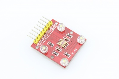
Model:SEN32001T
Specifications
- Working voltage: 3V-5V
- Breakout all IC TCS3200 PINS
- VCC:3V-5V
- GND:GND
- S0-S3, E0,OUT: Communication interface
- The better distance between the TCS3200 and the tested object is 1cm
- Dimension: 3cm*2.7cm
Application
- Color detection solution
- Color identification device
PinOut
| Pin Name | I/O | DESCRIPTION |
|---|---|---|
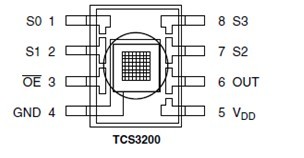
| GND(4) | Power supply ground. All voltages are referenced to GND | |
| OE(3) | I | Enable for fo (active low). |
| OUT | O | Output frequency (fo). |
| S0,S1(1,2) | I | Output frequency scaling selection inputs. |
| S2,S3(7,8) | I | Photodiode type selection inputs |
| VDD(5) | Supply voltage |
Usage
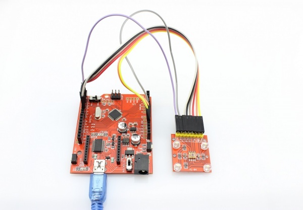
Hardware Connection
S0,S1,S2,S3
To TCS3002D, when choose a color filter, it can allow only one particular color to get through and prevent other color. For example, when choose the red filter, Only red incident light can get through, blue and green will be prevented. So we can get the red light intensity. Similarly ,when choose other filters we can get blue or green light.
TCS3002D has four photodiode types. Red , blue, green and clear, reducing the amplitude of the incident light uniformity greatly, so that to increase the accuracy and simplify the optical. When the light project to the TCS3002D we can choose the different type of photodiode by different combinations of S2 and S3. Look at the form as follows.
| S0 | S1 | OUTPUT FREQUENCY SCALING (fo) |
|---|---|---|
| L | L | Power down |
| L | H | 2% |
| H | L | 20% |
| H | H | 100% |
TCS3002D can output the frequency of different square wave (occupies emptiescompared 50%),different color and light intensity correspond with different frequency of square wave. There is a relationship between the output and light intensity. The range of the typical output frequency is 2HZ~500KHZ. We can get different scaling factor by different combinations of S0 and S1. Look at the form as follows.
| S2 | S3 | PHOTODIODE TYPE |
|---|---|---|
| L | L | RED |
| L | H | BLUE |
| H | L | Clear (no filter) |
| H | H | GREEN |
Demo Code
1.Copy and paste code below to a new Arduino sketch.
int s0=3,s1=4,s2=5,s3=6;
int out=2;
int flag=0;
byte counter=0;
byte countR=0,countG=0,countB=0;
void setup()
 {
 Serial.begin(115200);
 pinMode(s0,OUTPUT);
 pinMode(s1,OUTPUT);
 pinMode(s2,OUTPUT);
 pinMode(s3,OUTPUT);

 }
void TCS()
 {
 flag=0;
 digitalWrite(s1,HIGH);
 digitalWrite(s0,HIGH);
 digitalWrite(s2,LOW);
 digitalWrite(s3,LOW);
 attachInterrupt(0, ISR_INTO, CHANGE);
 timer0_init();

 }
void ISR_INTO()
 {
 counter++;
 }
 void timer0_init(void)
 {
  TCCR2A=0x00;
  TCCR2B=0x07;   //the clock frequency source 1024 points
  TCNT2= 100;    //10 ms overflow again
  TIMSK2 = 0x01; //allow interrupt
 }
 int i=0;
 ISR(TIMER2_OVF_vect)//the timer 2, 10ms interrupt overflow again. Internal overflow interrupt executive function
{
    TCNT2=100;
    flag++;
 if(flag==1)
  {
    countR=counter;
    Serial.print("red=");
    Serial.println(countR,DEC);
    digitalWrite(s2,HIGH);
    digitalWrite(s3,HIGH);
  }
  else if(flag==2)
   {
    countG=counter;
    Serial.print("green=");
    Serial.println(countG,DEC);
    digitalWrite(s2,LOW);
    digitalWrite(s3,HIGH);
   }
   else if(flag==3)
    {
    countB=counter;
    Serial.print("blue=");
    Serial.println(countB,DEC);
    Serial.println("\n");
    digitalWrite(s2,LOW);
    digitalWrite(s3,LOW);

    }
    else if(flag==4)
     {
     flag=0;
     }
       counter=0;
}
void loop()
 {
  TCS();
while(1);
 }
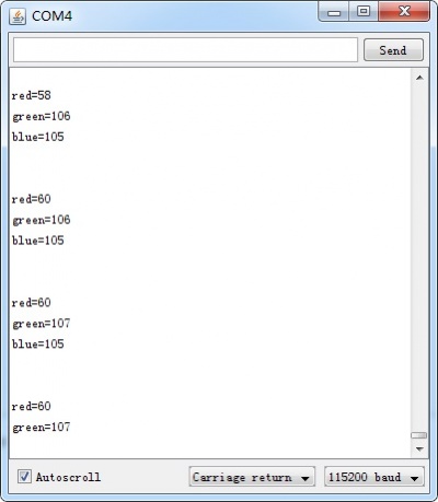
2.Open the serial monitor, you can see the test result:
Resource
- Demo code
- schematic


