32u4 with Lora RFM95 IOT Board-868MHz
Introduction
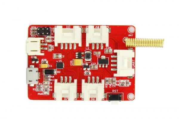
The 32u4 with Lora RFM95 IOT Board consists of the mega24u and the wireless RF module RFM95. The module can accomplish long distance transmission of data, that is, and it can provide long range spread spectrum communication and high anti-interference. It also has the function of transmitting data through the wall.This board is small and easy to carry,and it can be compatible with both USAR and I2C.The wireless transmission module is mainly used in remote control, telemetry, remote communication equipment, robot control, wireless communications and so on. Its high anti-interference can give your project a certain degree of convenience.
Model: WIR01322B

Features
- LoRaTM Modem
- Operating frequency: 868MHZ@RFM95
- Output power: 20dbm
- Maximum emission current: 120mA
- Current accepted: 12mA
- Sleep current 2ua
- Transmission rate: 300kbps
- Power: 3.7-5
Specifications
- 168 dB maximum link budget
- Excellent blocking immunity
- Compatible with I2C and USAR
- Rechargeable and uninterrupted
- Analog port and digital port
- Long distance
- Automated meter reading
- Built-in temperature sensor and low battery indicator
- Built-in bit synchronizer for clock recovery
- Dimensions(mm):62.0(L)x37.0(W)x9.0(H)
Interface Function
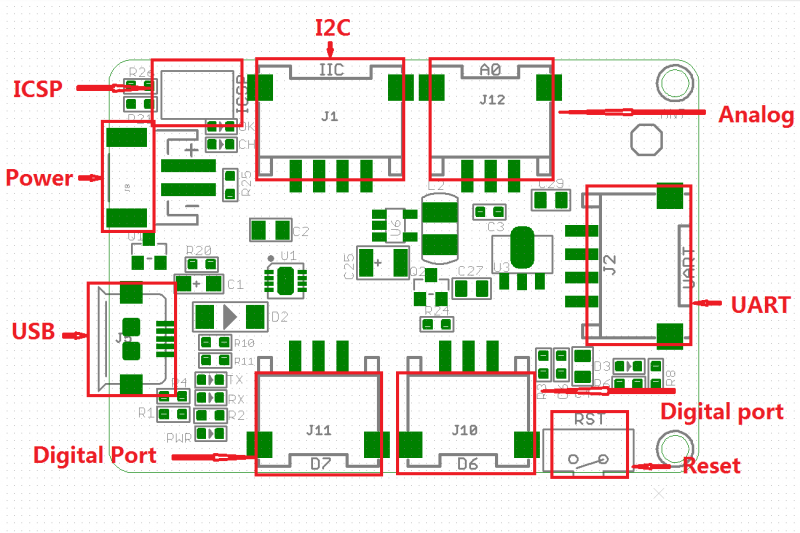
ICSP:2.0mm spacing ICSP package
Usage
1.Connect
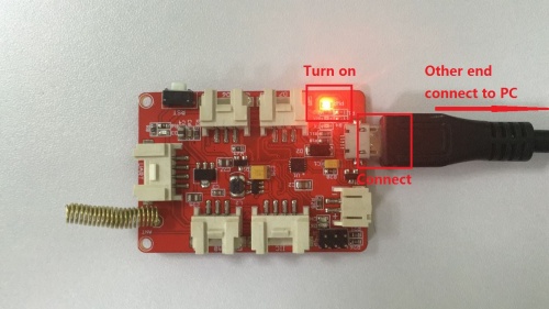
a.Connect USB and the other end connect to PC.When the board is working properly, PMR LED turn on,as follow picture:
b.Connect any two pieces of board onto the computer by USB, the two antennas corresponding to each other, as shown in the following picture:
2.Download the file
1.Download the RadioHead library and put the RadioHead file under the Arduino IDE installation directory Library
3.Download
3.Copy the following code, one is the sending program, one for the receiving program, downloaded to two boards:
client code
// rf95_client.pde
// -*- mode: C++ -*-
// Example sketch showing how to create a simple messageing client
// with the RH_RF95 class. RH_RF95 class does not provide for addressing or
// reliability, so you should only use RH_RF95 if you do not need the higher
// level messaging abilities.
// It is designed to work with the other example rf95_server
// Tested with Anarduino MiniWirelessLoRa, Rocket Scream Mini Ultra Pro with
// the RFM95W, Adafruit Feather M0 with RFM95

#include <SPI.h>
#include <RH_RF95.h>

// Singleton instance of the radio driver
//RH_RF95 rf95;
RH_RF95 rf95(10, 7); // Rocket Scream Mini Ultra Pro with the RFM95W
//RH_RF95 rf95(8, 3); // Adafruit Feather M0 with RFM95

// Need this on Arduino Zero with SerialUSB port (eg RocketScream Mini Ultra Pro)
//#define Serial SerialUSB

void setup()
{
  // Rocket Scream Mini Ultra Pro with the RFM95W only:
  // Ensure serial flash is not interfering with radio communication on SPI bus
//  pinMode(4, OUTPUT);
//  digitalWrite(4, HIGH);

  Serial.begin(9600);
  while (!Serial) ; // Wait for serial port to be available
  if (!rf95.init())
    Serial.println("init failed");
  // Defaults after init are 434.0MHz, 13dBm, Bw = 125 kHz, Cr = 4/5, Sf = 128chips/symbol, CRC on

  // The default transmitter power is 13dBm, using PA_BOOST.
  // If you are using RFM95/96/97/98 modules which uses the PA_BOOST transmitter pin, then
  // you can set transmitter powers from 5 to 23 dBm:
//  driver.setTxPower(23, false);
  // If you are using Modtronix inAir4 or inAir9,or any other module which uses the
  // transmitter RFO pins and not the PA_BOOST pins
  // then you can configure the power transmitter power for -1 to 14 dBm and with useRFO true.
  // Failure to do that will result in extremely low transmit powers.
//  driver.setTxPower(14, true);
   if (!rf95.setFrequency(868.0)){
    Serial.println("setFrequency failed");
    while(1)
    ;
    }
}

void loop()
{
  Serial.println("Sending to rf95_server");
  // Send a message to rf95_server
  uint8_t data[] = "Hello World!";
  rf95.send(data, sizeof(data));

  rf95.waitPacketSent();
  // Now wait for a reply
  uint8_t buf[RH_RF95_MAX_MESSAGE_LEN];
  uint8_t len = sizeof(buf);

  if (rf95.waitAvailableTimeout(3000))
  {
    // Should be a reply message for us now
    if (rf95.recv(buf, &len))
   {
      Serial.print("got reply: ");
      Serial.println((char*)buf);
    }
    else
    {
      Serial.println("recv failed");
    }
  }
  else
  {
    Serial.println("No reply, is rf95_server running?");
  }
  delay(1000);
}
server code
// -*- mode: C++ -*-
// Example sketch showing how to create a simple messageing server
// with the RH_RF95 class. RH_RF95 class does not provide for addressing or
// reliability, so you should only use RH_RF95  if you do not need the higher
// level messaging abilities.
// It is designed to work with the other example rf95_client
// Tested with Anarduino MiniWirelessLoRa, Rocket Scream Mini Ultra Pro with
// the RFM95W, Adafruit Feather M0 with RFM95

#include <SPI.h>
#include <RH_RF95.h>

// Singleton instance of the radio driver
//RH_RF95 rf95;
 RH_RF95 rf95(10, 7); // Rocket Scream Mini Ultra Pro with the RFM95W
//RH_RF95 rf95(8, 3); // Adafruit Feather M0 with RFM95

// Need this on Arduino Zero with SerialUSB port (eg RocketScream Mini Ultra Pro)
//#define Serial SerialUSB

int led = 9;

void setup()
{
  // Rocket Scream Mini Ultra Pro with the RFM95W only:
  // Ensure serial flash is not interfering with radio communication on SPI bus
//  pinMode(4, OUTPUT);
//  digitalWrite(4, HIGH);

  pinMode(led, OUTPUT);
  Serial.begin(9600);
  //while (!Serial) ; // Wait for serial port to be available
  if (!rf95.init())
    Serial.println("init failed");
  // Defaults after init are 434.0MHz, 13dBm, Bw = 125 kHz, Cr = 4/5, Sf = 128chips/symbol, CRC on

  // The default transmitter power is 13dBm, using PA_BOOST.
  // If you are using RFM95/96/97/98 modules which uses the PA_BOOST transmitter pin, then
  // you can set transmitter powers from 5 to 23 dBm:
//  driver.setTxPower(23, false);
  // If you are using Modtronix inAir4 or inAir9,or any other module which uses the
  // transmitter RFO pins and not the PA_BOOST pins
  // then you can configure the power transmitter power for -1 to 14 dBm and with useRFO true.
  // Failure to do that will result in extremely low transmit powers.
//  driver.setTxPower(14, true)
    if (!rf95.setFrequency(868.0)){
    Serial.println("setFrequency failed");
    while(1)
    ;
    }
}

void loop()
{
  if (rf95.available())
  {
    // Should be a message for us now
    uint8_t buf[RH_RF95_MAX_MESSAGE_LEN];
    uint8_t len = sizeof(buf);
    if (rf95.recv(buf, &len))
    {
      digitalWrite(led, HIGH);
//      RH_RF95::printBuffer("request: ", buf, len);
      Serial.print("got request: ");
      Serial.println((char*)buf);
//      Serial.print("RSSI: ");
//      Serial.println(rf95.lastRssi(), DEC);

      // Send a reply
      uint8_t data[] = "And hello back to you";
      rf95.send(data, sizeof(data));
      rf95.waitPacketSent();
      Serial.println("Sent a reply");
       digitalWrite(led, LOW);
    }
    else
    {
      Serial.println("recv failed");
    }
  }
}
4.Observe
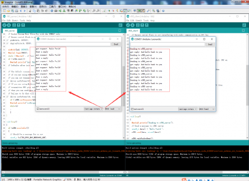
Open Arduino IDE serial monitor, and then observe the serial port debugging window display data, as shown in the following figure:


