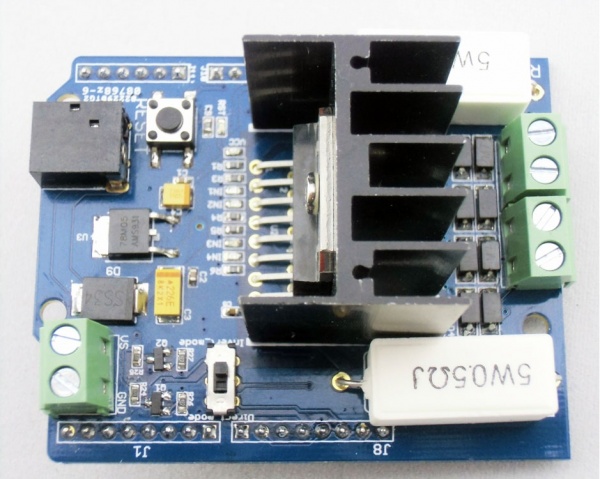
Motor Shield v1.0
Description
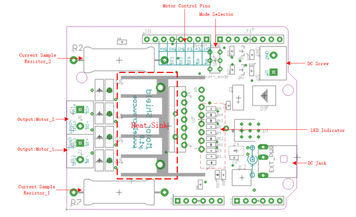
The Motor Shield is a platform for robotics and mechanical applications based on LM298N. It can be used to drive 2 DC motor or a 4-wire stepper. When controlling 2 DC motor, Only 4 control pins were needed, which makes this shield easier to control, and saves the control pins of controller. The Drive current can be up to 2A per motor output thanks to the heat sink added. you can measure the driver current with the added resistance, which would makes your control system more smart.
Model: (Discontinued)
Features
- The logic control voltage: 4.5~5.5V
- Motor Supply Voltage: 6~ 15V
- Reduced control pins needed
- Measurement for driver current
- Drive part of the operating current Io: 2A
- Maximum power dissipation: 25W (T = 75 degree Celsius)
- Operating temperature: -25 degree Celsius ~ +130 degree Celsius
- Drive Type: Dual high-power H-bridge driver
Specification
| Item | Min | Typical | Max | Unit |
|---|---|---|---|---|
| Operating Voltage | 4.5 | 5.0 | 5.5 | VDC |
| Drive Voltage | 6 | 12 | 15 | V |
| Output Current | / | / | 2 | A |
| Dimension | cm | |||
| Weight | g | |||
Interface
Usage
Pin Routing
Plug the motor shield onto Arduino or Crowduino, the motor shield pins connects Arduino pins as below:
| Pin Name | Direction | Connection to Arduino | Description |
|---|---|---|---|
| EA | Input | D9 | Motor_1 enable pin |
| EB | Input | D10 | Motor_2 enable pin |
| IN1 | Input | D8 | Positive Controlling of Motor_1 |
| IN2 | Input | D11 | Negative Controlling of Motor_1 |
| IN3 | Input | D12 | Positive Controlling of Motor_2 |
| IN4 | Input | D13 | Negative Controlling of Motor_2 |
| M1-, M1+ | Output | / | Outputs to Motor_1 |
| M2-, M2+ | Output | / | Outputs to Motor_1 |
Control 2DC motors
With this motor shield, you can connect and control 2 DC motors simultaneously. There are 2 control modes you can select to control these motors.
- Derect_Mode:
Set the selector on the shield to "Derect_Mode", in this mode, 6 Arduino pins are needed to control the 2 DC motors. D8/D9/D11 are for motor_1 controlling, and D10/D12/D13 are for the motor_2 controlling. In this mode, follows the logic between EA(B) and INx with motor motion:
| EA(B) | IN1(IN3) | IN2(IN4) | Motion of MotorA(B) |
|---|---|---|---|
| 0 | x | x | Stop |
| 1 | 0 | 0 | Stop |
| 1 | 0 | 1 | Clockwise |
| 1 | 1 | 0 | Anticlockwise |
| 1 | 1 | 1 | Stop |
In this mode, 3 pins will be need to control each motor. 2 for rotate derection, and 1 for speed controlling.
const int pinI1=8;//I1
const int pinI2=11;//I2
const int speedpinA=9;//EA(PWM]
const int pinI3=12;//I3
const int pinI4=13;//I4
const int speedpinB=10;//EB(PWM]
void setup()
{
    for(int i=0;i<20;i++)
    pinMode(i,OUTPUT);
}
void loop()
{
    Test_Load_Left();
    delay(3000);
    clean_Output();
delay(1000);
Test_Load_Right();
 delay(3000);
}

void Test_Load_Left()
{
  digitalWrite(speedpinA,HIGH);// full PWM
  digitalWrite(speedpinB,HIGH);
  digitalWrite(pinI4,HIGH);
  digitalWrite(pinI3,LOW);
  digitalWrite(pinI2,HIGH);
  digitalWrite(pinI1,LOW);
}
void Test_Load_Right()
{
  digitalWrite(speedpinA,HIGH);// full PWM 255
  digitalWrite(speedpinB,HIGH);
  digitalWrite(pinI1,HIGH);
  digitalWrite(pinI2,LOW);
  digitalWrite(pinI3,HIGH);
  digitalWrite(pinI4,LOW);
  }
void clean_Output()
{
  digitalWrite(speedpinA,LOW);// full PWM 255
  digitalWrite(speedpinB,LOW);
}
- Invert_Mode
Obviously, I/O pins is so precious for Arduino board especily when you need to make a real project. So, Elecrow motor Shield add the functions to control the motors with less pins. In the "Invert_Mode", only 4 control pins are needed to control 2 DC motors, 2 pins for each motor.
First, adjust the Control mode to Invert Mode, in this mode, D8/D9 are used to control motor 1, while D10/D12 are used to control motor The motor can be controlled by the corresponding control pins as the following table:
| D8(/D12): Direction Control | D9(/D10): Speed Control | Motor1(/2) Action |
|---|---|---|
| x | L | NO Action |
| H | H | Forward(Full Speed) |
| L | H | Backward(Full Speed) |
| H or L | PWM | PWM Speed Control |
In this mode, Just 4 pins are needed to control the motors:
void Test_Load_Left()
{
  digitalWrite(speedpinA,HIGH);// full PWM
  digitalWrite(speedpinB,HIGH);
  digitalWrite(pinI3,LOW);
  digitalWrite(pinI1,LOW);
}
void Test_Load_Right()
{
  digitalWrite(speedpinA,HIGH);// full PWM 255
  digitalWrite(speedpinB,HIGH);
  digitalWrite(pinI1,HIGH);
  digitalWrite(pinI3,HIGH);
  }
The connected 2 motors would rotate with a changing speed for this program.
Stepper Control
Connect a 4-wire stepper motor to motor shield refer to [ULN2003]
Note you need to adjust the control mode selector to Derect_mode to contol the stepper.
There is a lib: Stepper.h in Arduino IDE, users can use this library to control 4-wire stepper as below program:
#include <Stepper.h>
const int stepsPerRevolution = 200;  // change this to fit the number of steps per revolution
                                    // for your motor
// initialize the stepper library on pins 8 through 13:
Stepper myStepper(stepsPerRevolution, 8,11,12,13);
void setup() {
 // set the speed at 60 rpm:
 myStepper.setSpeed(60);
 // initialize the serial port:
 Serial.begin(9600);
 pinMode(9,OUTPUT);
 pinMode(10,OUTPUT);
 digitalWrite(9,HIGH);
 digitalWrite(10,HIGH);
}
void loop() {
 // step one revolution  in one direction:
  Serial.println("clockwise");
 myStepper.step(stepsPerRevolution);
 delay(500);
  // step one revolution in the other direction:
 Serial.println("counterclockwise");
 myStepper.step(-stepsPerRevolution);
 delay(500);
} The connected stepper would rotate with a changing direction for this progam.
Drive Current Measurement
The drive current of both channel can be measured by Arduino, which makes it smart in applications for auto monitoring. Two 0.5R Cement Power Resistors are added in this shield to achieve this. you can get the driver current for both channel with Arduino as following program:
int senA= A0;    // channel A current measurement
int senB =A1;    // channel B current measurement
int sensorValueA=0;
int sensorValueB=0;
double currentA=0;
double currentB=0;
void setup() {
}
void loop() {
 // read the value from the sensor:
 sensorValueA = analogRead(senA);
 sensorValueB = analogRead(senB);
 // canculate the driver current for both channel with: I=U/R
 currentA = sensorValueA/1024*5/0.5;
 currentB = sensorValueB/1024*5/0.5;
 delay(100);
}
In this program, Arduino get the voltage on Resistors for each channel. And then convert the voltage to current with Ohm's law. The Drive Current measurement would be useful in applications such as tire locking monitoring.
Support
You can go to our website or contact with techsupport@elecrow.com.
Resources
- L298datasheet
- Motor Shield v1.0 Eagle files
- Stepper control library for Arduino

