Pi Terminal
Description
Want a multifunctional integrated industrial control device? Pi Terminal, a new star in the industrial world, is looking forward to serving you! The 7-inch Pi Terminal with 1024*600 resolution is a multifunctional industrial control device based on Raspberry Pi CM4. It combines powerful hardware configuration with rich software ecology and is designed to meet the needs of diverse industrial applications. It is equipped with the powerful Raspberry Pi Compute Module 4 as the main control, with excellent real-time performance, and can quickly respond to and process real-time control and monitoring tasks. A highlight is the rich industrial interfaces and functional modules, including CAN bus, RS232/RS485, isolated digital IO, differential input ADC, relay control, etc., which fully meet the communication and control needs with various sensors, actuators and other devices. In addition, it also reserves speaker, headphone, microphone sockets and 4 programmable button interfaces, which makes it convenient for users to customize functions according to actual needs, increasing the interactivity and flexibility of the device.
Module: DIS01447T


Feature
- Using Raspberry Pi CM4 as the main controller, it has excellent computing power and performance, providing strong power for industrial applications;
- Integrated Node-RED visual programming, built-in Node-RED process editing and one-click deployment, compatible with all software running on Raspberry Pi. This powerful and intuitive programming environment allows developers to quickly build prototypes and test, greatly improving development efficiency and productivity;
- Powerful communication capabilities, supporting multiple wireless communication protocols such as WiFI, Bluetooth-compatible, 4G, and LoRa, equipped with Gigabit Ethernet, meeting the needs of high-speed wired networks, and enabling high-speed data transmission and remote monitoring between devices;
- Pi Terminal's multifunctional integrated design can be used as full-function devices such as HMI, PLC, gateway, tablet PC, etc., unifying data flow and creating a full-function integrated platform;
- Rich industrial interfaces, with CAN bus interface, support RS232/RS485 serial communication, integrated DIO, ADC, relay and other interfaces, fully meet the needs of equipment interconnection and control;
- Flexible customization, reserved 4 programmable button interfaces, with speaker and microphone interfaces, can be flexibly configured according to needs;
- Low power consumption, the maximum power consumption is only 9W, especially suitable for energy-saving scenarios; and the 12V~36V wide voltage design can better adapt to different host power supply solutions;
- Industrial-grade design, IP65 front panel dust and waterproof, electronic components support high temperature operation, hardware design fully considers industrial requirements, suitable for harsh industrial environments.
Specifications
| Processor (CM4) | |
|---|---|
| CPU/SoC | Broadcom BCM2711 Quad-core Cortex-A72 (ARM v8) 64-bit SoC @ 1.5GHz |
| System Memory | 4GB(LPDDR4-3200 SDRAM) |
| Storage | Operating system 64G TF card((lmage File Loaded)), compatible with SSD slot expansion (No eMMC) |
| Operating System | Raspbian (compatible with Node-RED), compatible with all software running on Raspberry Pi (pre-installed system) |
| Display | |
| Size | 7 inch |
| Panel Type | IPS Panel |
| Resolution | 1024(RGB)×600 |
| Aspect Ratio | 4:3 |
| Brightness | 450 cd/m² |
| Touch Type | 5-point Capacitive Touch |
| Wireless Communication | |
| Wi-Fi | 2.4 /5.0 GHz on CM4 |
| Bluetooth | BLE 5.0 on CM4 |
| LoRa | Reserved Mini-PCIe socket (Optional) |
| LTE | Reserved Mini-PCIe socket (Optional) |
| Interfaces (edge) | Counterclockwise sorting |
| GPIO | 4pin, GND/IO10/IO22/3.3V |
| Relay | 2*3pin, see below for detailed definitions |
| DO&DI | 2*4pin, see below for detailed definitions |
| CAN&RS485&ADC | 2*6pin, see below for detailed definitions |
| RS232 | DB9 interface/ 9pin |
| Type-C | USB 2.0/ USB to UART |
| ETH | 1 x 10/100/1000 Mbps |
| HD | HDMI 2.0/ support video output up to 4K @ 60 fps |
| HP | 3.5mm/ support headphone and microphone |
| USB*2 | USB-A 2.0 |
| DC | Power with 12-36V/3A |
| TF Card Slot | With a 64GB TF card (Image file loaded) |
| SIM Card Slot | Compatible with Nano SIM card |
| 2*4pin | GND/DM2/DP2/5V, GND/DM1/DP1/5V |
| 2*20pin | CM4 native GPIO interface, all GPIO port internal default set high level is 3.3V. Some GPIO interfaces are multiplexed internally as SPI/I2C/UART interfaces and cannot be used. |
| CAM*2 | 2*15pin FPC/CSI camera interface |
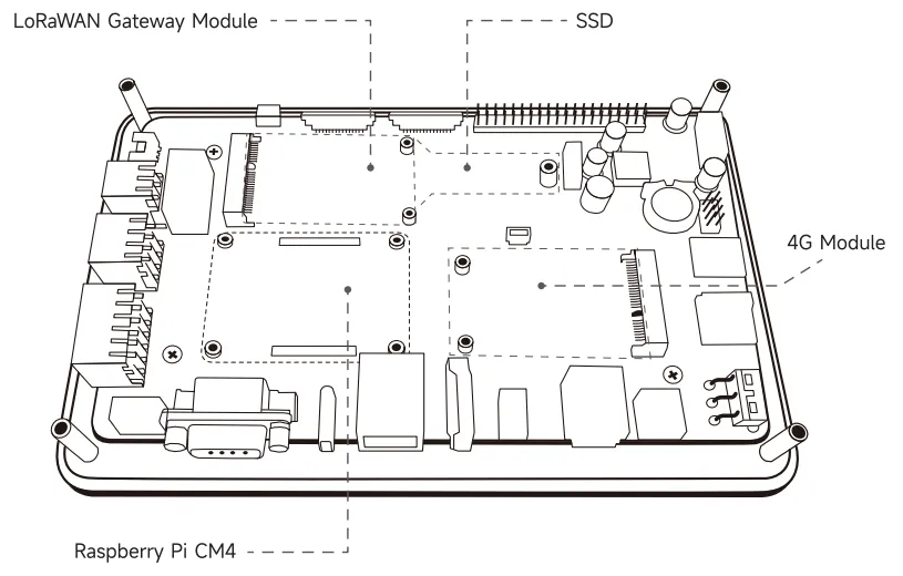
| Interfaces (inside) | |
| CM4 Socket | Works with all versions of the Raspberry PI CM4, pay attention to the installation direction. |
| Mini PCIe-4G | 52pin, see below for detailed definitions |
| Mini PCIe-Lora/SSD | 52pin, see below for detailed definitions |
| 2*2pin | POE |
| Fan | 4pin SH1.0/power 5V/compatible with Raspberry PI 5-4PIN JST interface/adjust fan speed |
| SPK*2 | 2pin PH2.0 |
| Internal function | |
| Buzzer | Top sound electromagnetic type |
| RTC | Integrated RTC circuit/pre-installed CR1220 battery |
| Hardware encryption | Use ATECC608A for encryption |
| Watchdog | Equip with |
| Switch | |
| Power | Up is OFF, down is ON |
| Sleep/Wake | To control screen is on or off |
| Environmental spec | |
| Front panel IP rating | IP65 |
| Operating temperature | -10~60℃ |
| Storage temperature | -20~70℃ |
| Relative humidity | 10~90% |
| Mechanical | |
| Front glass thickness | 1.8mm |
| with acrylic case | |
| Dimension | 192x125x46mm |
| Net weight | 676g |
| Without acrylic case | |
| Dimension | 182x115x29mm |
| Net weight | 389g |
| Certification | |
| CE | FCC |
Overview
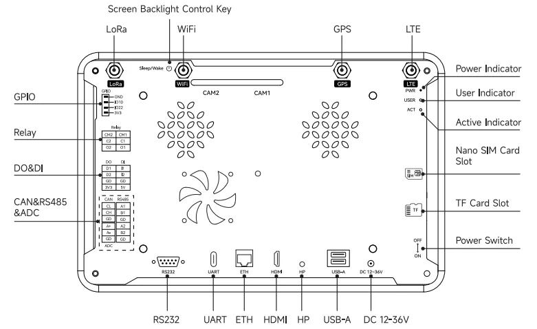
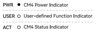
LED Indicator
| Name | Description |
|---|---|
| PWR | Red/light on with power, off without |
| USER | Green/User-defined function indicator, change the on-off frequency |
| ACT | Green/CM4 Internal system status indicators, used to indicate the CM4 system status. |
Pin Definition
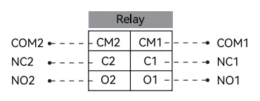
| silk-screen | Signal | Description |
|---|---|---|
| CM1 | COM1 | Communication port 1 |
| CM2 | COM2 | Communication port 2 |
| C1 | NC1 | Not connected 1 |
| C2 | NC2 | Not connected 2 |
| O1 | NO1 | Normal open 1 |
| O2 | NO2 | Normal open 2 |
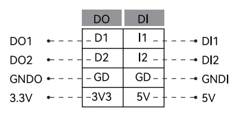
| silk-screen | Signal | Description |
|---|---|---|
| I1 | DI1 | Digital input 1 |
| I2 | DI2 | Digital input 2 |
| O1 | DO1 | Digital output 1 |
| O2 | DO2 | Digital output 1 |
| GD | GNDI | Digital input ground |
| GD | GNDO | Digital output ground |
| 5V | 5V | Power with 5V |
| 3V3 | 3.3V | Power with 3.3V |
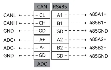
| silk-screen | Signal | Description |
|---|---|---|
| CL | CANL | CAN low signal |
| CH | CANH | CAN high signal |
| GD | GND | CAN ground |
| A+ | ADC+ | ADC reference voltage positive |
| A- | ADC- | ADC reference voltage negative |
| GD | GND | ADC ground |
| A1 | 485A1+ | RS485 A1 positive signal |
| B1 | 485B1- | RS485 B1 negative signal |
| GD | 485GND | RS485 ground |
| A2 | 485A2+ | RS485 A2 positive signal |
| B2 | 485B2- | RS485 B2 negative signal |
| GD | 485GND | RS485 ground |
Mini PCIe-4G Definition
Used with ELE7670 4G module
| NO | MiniPCIE PIN | ELE7670 4G PIN | IO TYPE | Fuction |
|---|---|---|---|---|
| 1 | WAKE# | NC | ||
| 2 | 3.3VAUX | VBAT | Power | A7670/SIM7670 Power PIN |
| 3 | COEX1 | NC | ||
| 4 | GND | GND | Ground | Ground PIN |
| 5 | COEX2 | NC | ||
| 6 | 1.5V | NC | ||
| 7 | CLKREQ# | NC | ||
| 8 | UIM PWR | USIM VDD | Power | USIM Card VDD PIN |
| 9 | GND | GND | Ground | Ground PIN |
| 10 | UIM DATA | USIM DATA | DIO | USIM Card DATA PIN |
| 11 | REFCLK- | NC | ||
| 12 | UIM CLK | USIM CLK | DI | USIM Card CLK PIN |
| 13 | REFCLK+ | NC | ||
| 14 | UIM RESET | USIM RST | DI | USIM Card CLK PIN |
| 15 | GND | GND | ||
| 16 | UIM VPP | USIM DET | DO | USIM Card DET PIN |
| 17 | Reserved | NC | ||
| 18 | GND | GND | Ground | Ground PIN |
| 19 | Reserved | NC | ||
| 20 | W DISABLE# | GPS 1PPS | DO | A7670/SIM7670 GNSS 1PPS PIN |
| 21 | GND | GND | Ground | Ground PIN |
| 22 | PERST# | P RESET | DI | A7670/SIM7670 RESRET PIN |
| 23 | PERn0 | NC | ||
| 24 | 3.3VAUX | VBAT | Power | A7670/SIM7670 Power PIN |
| 25 | PERp0 | NC | ||
| 26 | GND | GND | Ground | Ground PIN |
| 27 | GND | GND | Ground | Ground PIN |
| 28 | 1.5V | NC | ||
| 29 | GND | GND | Ground | Ground PIN |
| 30 | SMB CLK | I2C CLK | DI | A7670/SIM7670 I2C CLK PIN |
| 31 | PETn0 | NC | ||
| 32 | SMB DATA | I2C SDA | DIO | A7670/SIM7670 I2C SDA PIN |
| 33 | PETp0 | VDD 1V8 | Power | A7670/SIM7670 1.8V Power Output |
| 34 | GND | GND | Ground | Ground PIN |
| 35 | GND | GND | Ground | Ground PIN |
| 36 | USB D- | USB D- | DIO | A7670/SIM7670 USB D- PIN |
| 37 | GND | GND | Ground | Ground PIN |
| 38 | USB D+ | USB D+ | DIO | A7670/SIM7670 USB D+ PIN |
| 39 | 3.3VAUX | VBAT | A7670/SIM7670 Power PIN | |
| 40 | GND | GND | ||
| 41 | 3.3VAUX | VBAT | Power | A7670/SIM7670 Power PIN |
| 42 | LED WWAN# | NET LTE | DO | A7670/SIM7670 NET LTE LED PIN |
| 43 | GND | GND | Ground | Ground PIN |
| 44 | LED WWAN# | NC | ||
| 45 | Reserved | NC | ||
| 46 | LED WWAN# | P_PWRKEY | DI | A7670/SIM7670 PWRKEY PIN |
| 47 | Reserved | NC | ||
| 48 | 1.5V | NC | ||
| 49 | Reserved | NC | ||
| 50 | GND | GND | Ground | Ground PIN |
| 51 | Reserved | NC | ||
| 52 | 3.3VAUX | VBAT | Power | A7670/SIM7670 Power PIN |
Mini PCIe-LoRa Definition
Used with LR1302 gateway module EU868 or LR1302 gateway module US915
| NO | MiniPCIE PIN | LR1302 PIN | IO TYPE | Fuction |
|---|---|---|---|---|
| 1 | WAKE# | NC | ||
| 2 | 3.3VAUX | 3V3 | Power | |
| 3 | COEX1 | NC | ||
| 4 | GND | GND | Ground | Ground PIN |
| 5 | COEX2 | NC | ||
| 6 | 1.5V | NC | ||
| 7 | CLKREQ# | NC | ||
| 8 | UIM PWR | SX1261_BUSY | DO | SX1261 BUSY PIN |
| 9 | GND | GND | Ground | Ground PIN |
| 10 | UIM DATA | SX1261_RST | DI | SX1261_RST PIN |
| 11 | REFCLK- | NC | ||
| 12 | UIM CLK | NC | ||
| 13 | REFCLK+ | NC | ||
| 14 | UIM RESET | NC | ||
| 15 | GND | GND | Ground | Ground PIN |
| 16 | UIM VPP | NC | ||
| 17 | Reserved | NC | ||
| 18 | GND | GND | Ground | Ground PIN |
| 19 | Reserved | 1PPS | ||
| 20 | W DISABLE# | NC | ||
| 21 | GND | GND | Ground | Ground PIN |
| 22 | PERST# | RESET | DI | SX1302 RESET PIN |
| 23 | PERn0 | NC | ||
| 24 | 3.3VAUX | 3V3 | Power | Power PIN |
| 25 | PERp0 | SX1261_CSN | SX1261_CSN PIN | |
| 26 | GND | GND | Ground | Ground PIN |
| 27 | GND | GND | Ground | Ground PIN |
| 28 | 1.5V | NC | ||
| 29 | GND | GND | Ground | Ground PIN |
| 30 | SMB CLK | I2C_SCL | DI | Temperature Sensor I2C CLK PIN |
| 31 | PETn0 | SX1261_IO2 | DIO | SX1261_IO2 PIN |
| 32 | SMB DATA | I2C SDA | DIO | Temperature Sensor I2C SDA PIN |
| 33 | PETp0 | SX1261_IO1 | DIO | SX1261_IO1 PIN |
| 34 | GND | GND | Ground | Ground PIN |
| 35 | GND | GND | Ground | Ground PIN |
| 36 | USB D- | USB D- | DIO | STM32 USB D- PIN |
| 37 | GND | GND | Ground | Ground PIN |
| 38 | USB D+ | USB D+ | DIO | STM32 USB D+ PIN |
| 39 | 3.3VAUX | 3V3 | Power PIN | |
| 40 | GND | GND | ||
| 41 | 3.3VAUX | 3V3 | Power | Power PIN |
| 42 | LED WWAN# | NC | ||
| 43 | GND | GND | Ground | Ground PIN |
| 44 | LED WWAN# | NC | ||
| 45 | Reserved | SPI_SCK | DI | SX1302 SPI SCK PIN |
| 46 | LED WWAN# | NC | ||
| 47 | Reserved | SPI_MISO | DIO | SX1302 SPI MISO PIN |
| 48 | 1.5V | NC | ||
| 49 | Reserved | SPI_MOSI | DIO | SX1302 SPI MOSI PIN |
| 50 | GND | GND | Ground | Ground PIN |
| 51 | Reserved | SPI_CS | DI | SX1302 SPI CS PIN |
| 52 | 3.3VAUX | 3V3 | Power | Power PIN |
M.2 Nvme SSD PCIe Definition
| NO | MiniPCIE PIN | M.2 Nvme SSD to PCIe adapter | IO TYPE | Fuction |
|---|---|---|---|---|
| 1 | WAKE# | PERST# | DI | M.2 Nvme SSD PERST# PIN |
| 2 | 3.3VAUX | 3V3 | Power | |
| 3 | COEX1 | NC | ||
| 4 | GND | GND | Ground | Ground PIN |
| 5 | COEX2 | PETn0/SATA-A- | DIO | M.2 Nvme SSD PETn0/SATA-A- PIN |
| 6 | 1.5V | CLKREQ# | DIO | M.2 Nvme SSD CLKREQ# PIN |
| 7 | CLKREQ# | PETp0/SATA-A+ | DIO | M.2 Nvme SSDPETp0/SATA-A+ PIN |
| 8 | UIM PWR | NC | ||
| 9 | GND | GND | Ground | Ground PIN |
| 10 | UIM DATA | NC | ||
| 11 | REFCLK- | PERp0/SATA-B- | DIO | M.2 Nvme SSD PERp0/SATA-B- PIN |
| 12 | UIM CLK | NC | ||
| 13 | REFCLK+ | PERn0/SATA-B+ | DIO | M.2 Nvme SSD PERn0/SATA-B+ PIN |
| 14 | UIM RESET | NC | ||
| 15 | GND | GND | Ground | Ground PIN |
| 16 | UIM VPP | NC | ||
| 17 | Reserved | REFCLKN | DIO | M.2 Nvme SSD REFCLKN PIN |
| 18 | GND | GND | Ground | Ground PIN |
| 19 | Reserved | REFCLKP | DIO | M.2 Nvme SSD REFCLKP PIN |
| 20 | W DISABLE# | NC | ||
| 21 | GND | GND | Ground | Ground PIN |
| 22 | PERST# | NC | ||
| 23 | PERn0 | NC | ||
| 24 | 3.3VAUX | 3V3 | Power | Power PIN |
| 25 | PERp0 | NC | ||
| 26 | GND | GND | Ground | Ground PIN |
| 27 | GND | GND | Ground | Ground PIN |
| 28 | 1.5V | NC | ||
| 29 | GND | GND | Ground | Ground PIN |
| 30 | SMB CLK | NC | ||
| 31 | PETn0 | NC | ||
| 32 | SMB DATA | NC | ||
| 33 | PETp0 | NC | ||
| 34 | GND | GND | Ground | Ground PIN |
| 35 | GND | GND | Ground | Ground PIN |
| 36 | USB D- | NC | ||
| 37 | GND | GND | Ground | Ground PIN |
| 38 | USB D+ | NC | ||
| 39 | 3.3VAUX | 3V3 | Power PIN | |
| 40 | GND | GND | ||
| 41 | 3.3VAUX | 3V3 | Power | Power PIN |
| 42 | LED WWAN# | NC | ||
| 43 | GND | GND | Ground | Ground PIN |
| 44 | LED WWAN# | NC | ||
| 45 | Reserved | NC | ||
| 46 | LED WWAN# | NC | ||
| 47 | Reserved | NC | ||
| 48 | 1.5V | NC | ||
| 49 | Reserved | NC | ||
| 50 | GND | GND | Ground | Ground PIN |
| 51 | Reserved | NC | ||
| 52 | 3.3VAUX | 3V3 | Power | Power PIN |
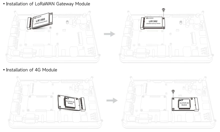
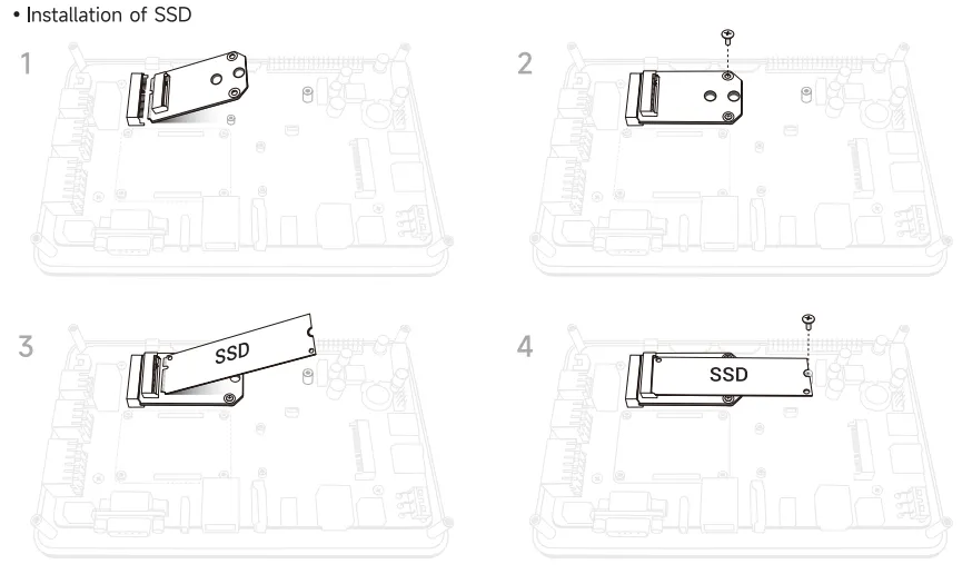
Installation