Crowtail- Logic Block
Introduction
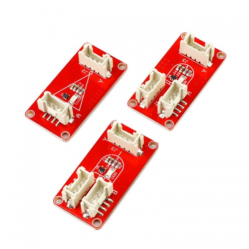
The Crowtail- Logic Block allows you to play with logic gates by literally plugging one into another and watching the progression of an input to an output! Each LogicBlock represents a different logic function: the NOT block is a simple inverter, where the output is the opposite of the input. The AND block will only output a 1 if both of the inputs are 1. The OR block will output a 1 if either of the inputs are 1. There are also input blocks and splitter blocks.
Model: CRT01235B
Features
Logic block:"AND" "OR" "NOT".
Output indicator.
Dual output port.
Dimensions(mm):40.0(L)x20.0(W)x9.8(H)
Theory
A digital logic circuit uses digital inputs to make logical decisions and produce digital outputs. Every logic circuit requires at least one input, before it can produce any kind of output. Digital logic inputs and outputs are usually binary. In other words they can only be one of two possible values.
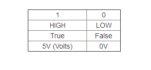
There are a number of ways to represent binary values: 1/0 is the least verbose and most common way. However, you may also see them in a boolean representation like TRUE/FALSE or HIGH/LOW. When the values are represented at a hardware level, they might be given actual voltage levels: 0V [Volts] is a 0, while a higher voltage - usually 3V or 5V - is used to represent a 1.
-
AND – The AND function produces a TRUE output if and only if all of its inputs are also TRUE.
-
OR – An OR will prove TRUE if any (one or more) of its inputs are also TRUE.
-
NOT – The NOT operator has only one input. The NOT operator negates its input, which means the output will be the opposite of the input.
AND Logic Block
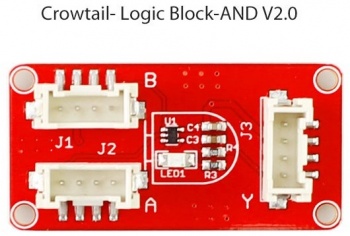
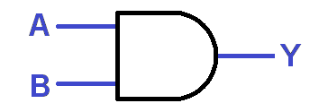
The AND LogicBlock is a two-input, single-output AND gate. The block is in a “D shape”, much like the AND gate circuit symbol. Each AND Gate Block has a single blue LED, which represents the output of the gate. If the LED is on, then that means the AND Gate is producing a 1 (TRUE, ON) at the output. If the LED is off, then the AND Gate’s output is 0.
Here’s a truth table for the AND Block:
The boolean equation symbol for AND is the centered dot (·). For example, the gate above could be represented by the equation: A · B = Y.
OR Logic Block
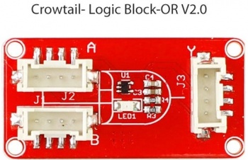
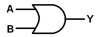
The OR LogicBlock is a two-input, single-output OR gate. The block is shaped like and OR gate circuit symbol – a convex arc on the output side, and a concave arc on the input side. Each OR Gate Block has a single yellow LED, which represents the output of the gate. If the LED is on, that means the OR Gate is producing a 1 (TRUE, ON) at the output. If the LED is off, then the OR Gate’s output is 0.
Here’s a truth table for the 2-input/1-output OR gate:
We can represent digital logic using boolean equations. The boolean equation symbol for OR is the plus sign (+). Here’s the boolean equation for the OR circuit above: A + B = Y.
NOT Logic Block
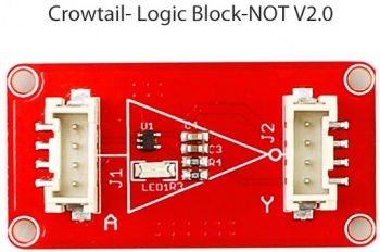
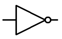
The NOT LogicBlock is a single-input, single-output NOT Gate. The Block comes in a trapezoid shape (it’s as close as we could get to the triangle-shaped NOT gate circuit symbol). Each NOT Block has a single red LED, which represents the output of the gate. If the LED is on, then that means the NOT Gate is producing a 1 (TRUE, ON) at the output. IF the LED is off, then the NOT gate’s output is 0.
An inverter’s truth table looks something like this:
When writing boolean equations, the NOT operation is usually indicated by a bar over any variables it inverts. For example the boolean equation for the circuit above would simply be: 
Usage
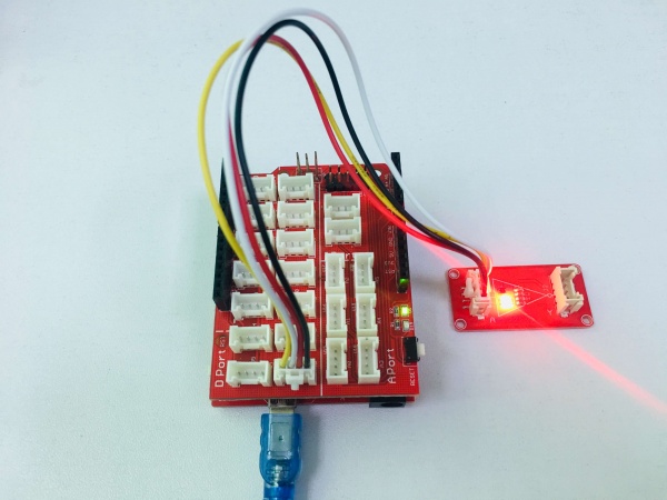
This simple demo is going to show you how to use the Crowtail Logic Block - NOT.
Hardware connection
2.Cope the code and upload it into your arduino board.
const int a=12;
void setup()
{
  pinMode(a,OUTPUT);

}
void loop()
{
 logic_not_test();
//  logic_or_test();

}

 void logic_not_test()
 {
 digitalWrite(a,LOW);

 }
In this example, we give a low level intput to it, you will see the LED be on(output high level).
