2 inch IPS Module
Description
This product is a 2.0inch IPS display module,it has a resolution of 320x240.it uses a 4-wire SPI communication method and the inner IC is ST7789.The module contains an LCD display and PCB backboard.

Features
- 2.0-inch color screen,support 65K color display,display rich colors
- 320X240 resolution, clear display
- IPS full view panel, super wide visual range
- Using the 4-line-SPI serial bus, it only takes a few IOs to illuminate the display
- Provide a rich STM32, C51 and MSP430 sample program
- Military-grade process standards, long-term stable work
- Provide underlying driver technical support
Specifications
| Item | Value |
|---|---|
| Display Color | RGB 65K color |
| Size | 291(Length)*190(Width)*46(Height)mm |
| Screen Size | 2.0(inch) |
| Type | IPS |
| Driver IC | ST7789 |
| Power Supply | DC 12V 2A |
| Resolution | 320*240 (Pixel) |
| Module Interface | 4-line SPI interface |
| Active Area (AA area) | 30.60x40.80 (mm) |
| Touch Screen | Unsupport |
| Module PCB Size | 36.48x61.12 (mm) |
| Angle of view | all angle |
| Operating Temperature | -10℃~60℃ |
| Storage Temperature | -20℃~70℃ |
| VCC power voltage | 3.3V |
| Rough Weight(Package containing) | 15g |
Interface
Pin Map
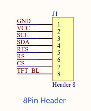
| Number | Pin Name | Description |
|---|---|---|
| 1 | GND | LCD Power ground |
| 2 | VCC | LCD power supply(3.3V) |
| 3 | SCL | LCD SPI bus clock signal |
| 4 | SDA | LCD SPI bus write data signal |
| 5 | RES | LCD reset control signal(Low level reset) |
| 6 | DC | LCD register / data selection control signal (Low level: register, high level: data) |
| 7 | CS | LCD chip select control signal (low level enable) |
| 8 | BLK | LCD backlight control signal (high level lighting, if you do not need control, please connect 3.3V) |
Hardware Configuration
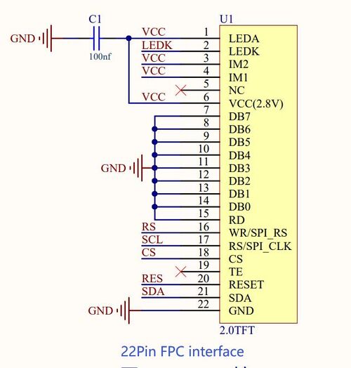
The LCD module hardware circuit comprises two parts: an LCD display control circuit and a backlight control circuit.
The LCD display control circuit is used to control the pins of the LCD, including control pins and data transfer pins.
if the backlight is not required to be be on and off, can be directly connected to the 3.3V if the backlight is not required to be be on and off, can be directly connected to the 3.3V power supply.

Usage
Hardware Connection
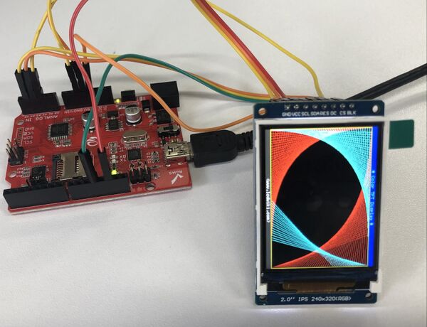
| Crowduino Uno | 2 inch IPS Module |
|---|---|
| GND | GND |
| 5V | VCC |
| 13 | SCL |
| 11 | SDA |
| A4 | RES |
| A3 | DC |
| A2 | CS |
| A0 | BLK |
Software
STEP1 Download 2.0inch_SPI_Arduino_Demo.zip
STEP2 Configure controller board&communication port
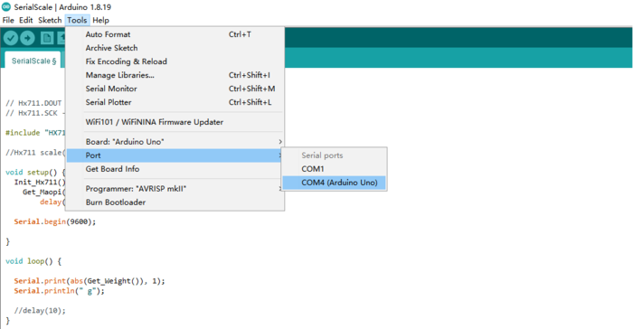
On top of the Arduino IDE, click “Tools>Board>” and select “Arduino Uno” from the available options
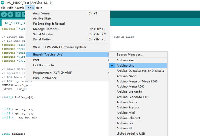
Select the COM port that indicates Arduino Uno. Please note that the actual numbers after the “COM” word will vary from computer to computer, so they could be different from the ones shown in the figure.
STEP3 Install libraries :Unzip Install libraries.zip and copy folder "LCDWIKI_GUI" and "LCDWIKI_SPI" to the libraries directory under the Arduino installation directory
 STEP4 Load the program to Arduino IDE
 STEP5 Click the
  to upload the code to the Crowduino board
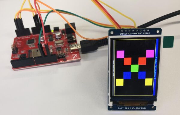
STEP6 After the program is downloaded, run it directly and observe the running status. If it can be displayed normally, the program runs successfully.
FAQS
You can list you question here or contact with techsupport@elecrow.com for technology support.
