Accelerometer Breakout-MMA7361
Introduction
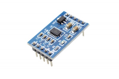
This is a breakout board for Freescale's MMA7361L three-axis analog accelerometer. The sensor requires a very low amount of power and has a g-select input which switches the accelerometer between ±1.5g and ±6g measurement ranges. Other features include a sleep mode, signal conditioning, a 1-pole low pass filter, temperature compensation, self test, and 0g-detect which detects linear freefall. Zero-g offset and sensitivity are factory set and require no external device.
Model:SPS07361S
Specification
- Two selectable measuring ranges (±1.5g, ±6g).
- Low current consumption: 400 µASleep mode: 3 µA.
- High sensitivity (800 mV/g at 1.5g).
- Seletable Sensitivity(±1.5g, ±6g).
- Fast turn on time (0.5 ms enable response time).
- Dimensions: 28 * 17mm.
Pin Definition
| Pin | Pad Name | Type | Description |
|---|---|---|---|
| 1 | 5V | P | 5V power |
| 2 | 3V3 | P | 3V3 power |
| 3 | GND | GND | GND |
| 4 | g-select | I | Input pin to initiate Self Test |
| 5 | Selftest | I | Self-Test |
| 6 | X | A | XOUT |
| 7 | Y | A | YOUT |
| 8 | Z | A | ZOUT |
| 9 | Sleep | I | Sleep mode, Low active |
| 10 | 0g-detect | O | Linear Freefall digital logic output signal |
A: Anlog Output I: Digital Input O: Digital Output
Usage
it would be very easy to use this module. here we introduce 2 ways to use this module. a simple method, and a comprehensive method.
Use this module with the default settings
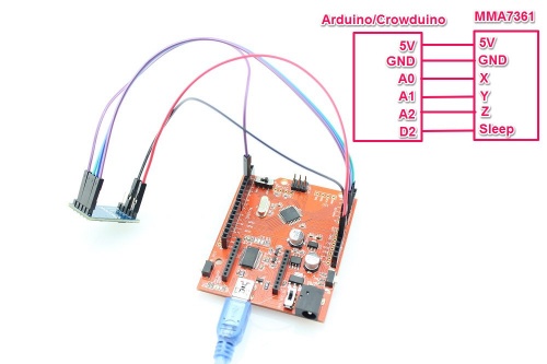
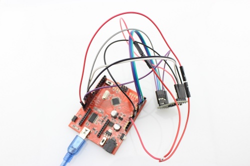
Connect the X/Y/Z pins of the MMA7361 moduel to A0/A1/A2 of your Arduino/Crowduino. and power it with 5V power supply. Connect the "SL" pin to logic HIGH to enable the MMA7361 work. you can get the test result with analogRead in Arduino IDE as below:
2.Copy the following program to Arduino IDE and upload to your Arduino/Crowduino:
// # Description:
// # read the data from the accelerometer in default setting

// # Connection:
// #        x  -> Analog pin 0
// #        y  -> Analog pin 1
// #        z  -> Analog pin 2
// #

const int Sleep=2;
void setup()
{
  Serial.begin(9600); // 9600 bps
  pinMode(Sleep, OUTPUT);
  digitalWrite(Sleep, HIGH);
}
void loop()
{
  int x,y,z;
  x=analogRead(0);
  y=analogRead(1);
  z=analogRead(2);
  Serial.print("x= ");
  Serial.print(x ,DEC);
  Serial.print(',');
  Serial.print("y= ");
  Serial.print(y ,DEC);
  Serial.print(',');
  Serial.print("z= ");
  Serial.println(z ,DEC);
  delay(100);
}
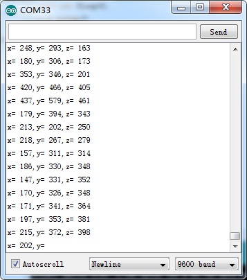
3.Open the Serial moniter , and set the baudrate to 9600, you will see the test value.
Use this module in a comprehensive way
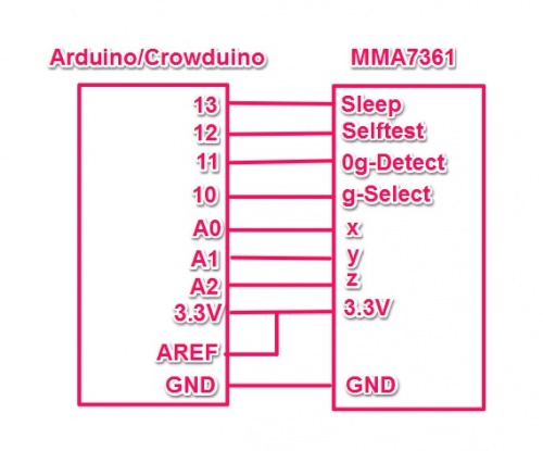
2.You can also use the MMA7371 Library to use this module, you should first connect this module to your Arduino/Crowduino as belows:
3.Install the library and upload the program to your Arduino. please refer to here to learn how to upload the program.
#include <AcceleroMMA7361.h>

AcceleroMMA7361 accelero;
int x;
int y;
int z;

void setup()
{
  Serial.begin(9600);
  accelero.begin(13, 12, 11, 10, A0, A1, A2);
  accelero.setARefVoltage(3.3);                   //sets the AREF voltage to 3.3V
  accelero.setSensitivity(LOW);                   //sets the sensitivity to +/-6G
  accelero.calibrate();
}

void loop()
{
  x = accelero.getXAccel();
  y = accelero.getYAccel();
  z = accelero.getZAccel();
  Serial.print("\nx: ");
  Serial.print(x);
  Serial.print(" \ty: ");
  Serial.print(y);
  Serial.print(" \tz: ");
  Serial.print(z);
  Serial.print("\tG*10^-2");
  delay(500);                                     //make it readable
}
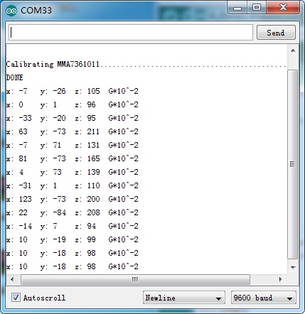
4.Open the serial monitor, after the calibrating, MMA 7361 will output the gravity on x, y and z axis. The photo below shows the output data when the accelerometor is lying flat, the gravity of Z axis is about 100(1 G).Please note keep this module flat when calibrating.
