Crowtail- SIM808
Description
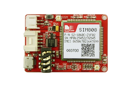
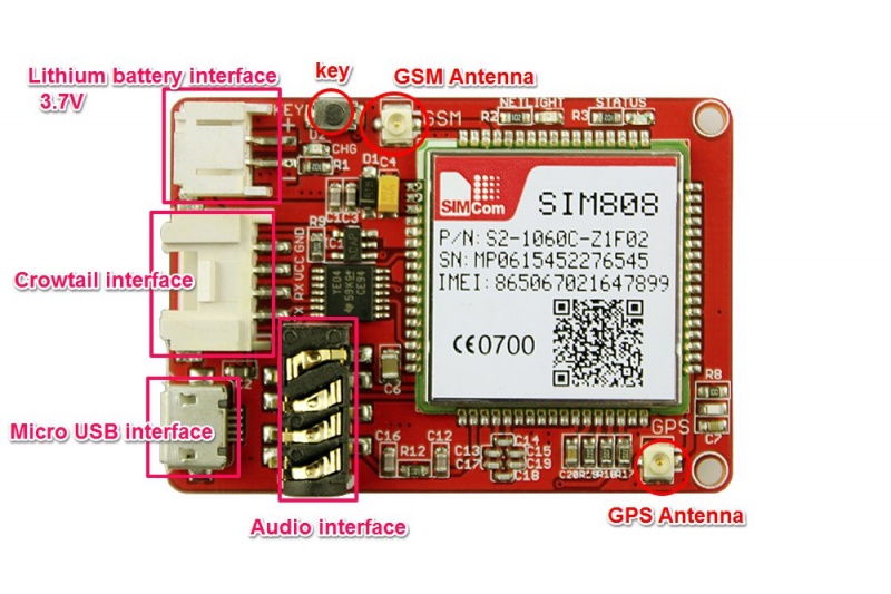
A new product of crowtail family, it’s a GSM and GPS two-in-one function module which is called Crowtail- SIM808. We add a Crowtail interface to it so that you can use easily. It is very small and based on the latest GSM/GPS module SIM808 from SIMCOM, supports GSM/GPRS Quad-Band network and combines GPS technology for satellite navigation. It has high GPS receive sensitivity with 22 tracking and 66 acquisition receiver channels that will lets you add location-tracking, voice, text, SMS and data to your project in an adorable little package. We can power it with a 3.7V lithium battery due to its specially charge interface. So it can use as a portable module, even you can attach it on your bicycle, it can obtain the speed/location information. A nice module that can achieve lots of functions. You need it now!
Model: CT0078SIM
Features
- Quad-band 850/900/1800/1900MHz
- GPRS mobile station class B
- Controlled by AT Command (3GPP TS 27.007, 27.005 and SIMCOM enhanced AT Commands)
- Integrated GPS/CNSS and supports A-GPS
- Supports 3.0V to 5.0V logic level
- Low power consumption, 1mA in sleep mode
- Supports GPS NMEA protocol
- Standard Micro SIM Card
- GPRS multi-slot class12 connectivity: max. 85.6kbps(down-load/up-load)
- Dimensions(mm):50.4(L)x35.0(W)x8.8(H)
Interface Function
Usage
AT command control
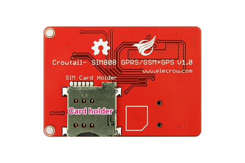
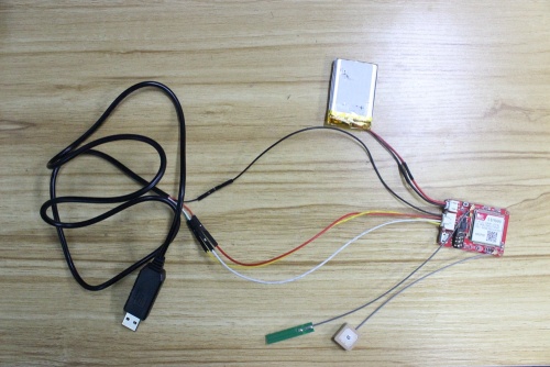
Connect the battery with crowtail SIM808, and then insert the SIM card into the card slot.
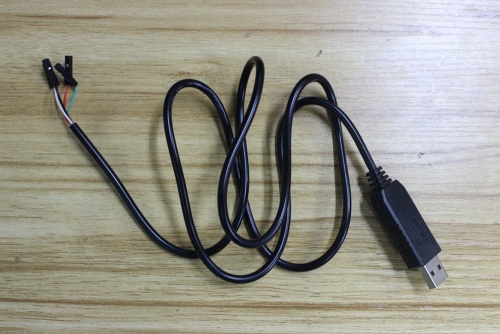
you need a usb to ttl cable for connect the module to computer as follow pictures show:
then connect it with your Crowtail- SIM808, you also need a 4 pin Crowtail to TTL cable.
OK, when you done those steps, it time to connect it with computer and then press the "key" button More than 3s, LED on the board will light up.
Now you can send the AT command to your board. you can try by using a com debug tool as you like, i have do a example for you:
Hardware
First of all, you need a Arduino UNO and a Crowtail base shield, and you have to connect the SIM808 with them, don't forget to power it with a 3.7V lipo battery. and hold on the key that i circled in the picture more than 3s, it will start to work. 
Arduino Test
Making a call: using Software UART
1.Copy the demo code as bellow and paste it in the IDE. 
2.Upload to your Arduino wired up to the moduleOnce uploaded to your Arduino, open up the serial console at 115200 baud speed to begin the tester sketch.
#include <SoftwareSerial.h>
SoftwareSerial mySerial(7, 8);
void setup()
{
mySerial.begin(19200);               // the GPRS baud rate
Serial.begin(19200);               // the GPRS baud rate
delay(2000);
mySerial.println("ATDxxxxxxxxx;"); // xxxxxxxxx is the number you want to dial.

if(mySerial.available())

Serial.print((unsigned char)mySerial.read());


delay(10000);
delay(10000);

mySerial.println("ATH"); //End the call.
if(mySerial.available())

Serial.print((unsigned char)mySerial.read());
}


void loop()
{
//Do nothing
}
Sending SMS: using Software UART
#include <SoftwareSerial.h>

SoftwareSerial mySerial(7, 8);

void setup()
{
mySerial.begin(19200);  //Default serial port setting for the GPRS modem is 19200bps 8-N-1
mySerial.print("\r");
delay(1000);                    //Wait for a second while the modem sends an "OK"
mySerial.print("AT+CMGF=1\r");    //Because we want to send the SMS in text mode
delay(1000);

//mySerial.print("AT+CSCA=\"+919032055002\"\r");  //Setting for the SMS Message center number,
//delay(1000);                                  //uncomment only if required and replace with
//the message center number obtained from
//your GSM service provider.
//Note that when specifying a tring of characters
// " is entered as \"

mySerial.print("AT+CMGS=\"+9184460xxxx\"\r");    //Start accepting the text for the message
//to be sent to the number specified.
//Replace this number with the target mobile number.
delay(1000);
mySerial.print("Hello,Elecrow!\r");   //The text for the message
delay(1000);
mySerial.write(0x1A);  //Equivalent to sending Ctrl+Z
}

void loop()
{
//We just want to send the SMS only once, so there is nothing in this loop.
//If we put the code for SMS here, it will be sent again and again and cost us a lot.
}
Using Sms to Control an LED Status
This example is controbuted by MChobby, for more information please visit: https://wiki.mchobby.be/index.php?title=SmsCommand
Send a SMS message "on" or "off" from your cellphone to the GPRS Shield to control the Digital Pin 13(LED) Status.
- The default Buffer of Rx in SoftwareSerial.h is 32/64, you may experience some data lose while the returns of SIM808 are many(Receiving SMS/TCPIP), you can try to change the Buffer of Rx in SoftwareSerial.h into
#define _SS_MAX_RX_BUFF 128 // RX buffer size
#include <SoftwareSerial.h>

SoftwareSerial mySerial(7, 8);

// EN: String buffer for the GPRS shield message

String msg = String("");
// EN: Set to 1 when the next GPRS shield message will contains the SMS message

int SmsContentFlag = 0;

// EN: Pin of the LED to turn ON and OFF depending on the received message

int ledPin = 13;

// EN: Code PIN of the SIM card (if applied)

//String SIM_PIN_CODE = String( "XXXX" );

void setup()
{
  mySerial.begin(19200);               // the GPRS baud rate
  Serial.begin(19200);                 // the GPRS baud rate

  // Initialize la PIN
  pinMode( ledPin, OUTPUT );
  digitalWrite( ledPin, LOW );
}

void loop()
{
    char SerialInByte;

    if(Serial.available())
    {
       mySerial.print((unsigned char)Serial.read());
     }
    else  if(mySerial.available())
    {
        char SerialInByte;
        SerialInByte = (unsigned char)mySerial.read();

        // EN: Relay to Arduino IDE Monitor

        Serial.print( SerialInByte );

        // -------------------------------------------------------------------
        // EN: Program also listen to the GPRS shield message.

        // -------------------------------------------------------------------

        // EN: If the message ends with <CR> then process the message

        if( SerialInByte == 13 ){
          // EN: Store the char into the message buffer

          ProcessGprsMsg();
         }
         if( SerialInByte == 10 ){
            // EN: Skip Line feed

         }
         else {
           // EN: store the current character in the message string buffer

           msg += String(SerialInByte);
         }
     }
}

// EN: Make action based on the content of the SMS.
//     Notice than SMS content is the result of the processing of several GPRS shield messages.

void ProcessSms( String sms ){
  Serial.print( "ProcessSms for [" );
  Serial.print( sms );
  Serial.println( "]" );

  if( sms.indexOf("on") >= 0 ){
    digitalWrite( ledPin, HIGH );
    Serial.println( "LED IS ON" );
    return;
  }
  if( sms.indexOf("off") >= 0 ){
    digitalWrite( ledPin, LOW );
    Serial.println( "LED IS OFF" );
    return;
  }
}

// EN: Send the SIM PIN Code to the GPRS shield

//void GprsSendPinCode(){
//  if( SIM_PIN_CODE.indexOf("XXXX")>=0 ){
//    Serial.println( "*** OUPS! you did not have provided a PIN CODE for your SIM CARD. ***" );
//    Serial.println( "*** Please, define the SIM_PIN_CODE variable . ***" );
//    return;
// }
//  mySerial.print("AT+CPIN=");
// mySerial.println( SIM_PIN_CODE );
}

// EN: Request Text Mode for SMS messaging

void GprsTextModeSMS(){
  mySerial.println( "AT+CMGF=1" );
}

void GprsReadSmsStore( String SmsStorePos ){
  // Serial.print( "GprsReadSmsStore for storePos " );
  // Serial.println( SmsStorePos );
  mySerial.print( "AT+CMGR=" );
  mySerial.println( SmsStorePos );
}

// EN: Clear the GPRS shield message buffer

void ClearGprsMsg(){
  msg = "";
}

// EN: interpret the GPRS shield message and act appropiately

void ProcessGprsMsg() {
  Serial.println("");
  Serial.print( "GPRS Message: [" );
  Serial.print( msg );
  Serial.println( "]" );

//  if( msg.indexOf( "+CPIN: SIM PIN" ) >= 0 ){
//     Serial.println( "*** NEED FOR SIM PIN CODE ***" );
 //    Serial.println( "PIN CODE *** WILL BE SEND NOW" );
 //    GprsSendPinCode();
//  }

  if( msg.indexOf( "Call Ready" ) >= 0 ){
     Serial.println( "*** GPRS Shield registered on Mobile Network ***" );
     GprsTextModeSMS();
  }

  // EN: unsolicited message received when getting a SMS message
  // FR: Message non sollicité quand un SMS arrive
  if( msg.indexOf( "+CMTI" ) >= 0 ){
     Serial.println( "*** SMS Received ***" );
     // EN: Look for the coma in the full message (+CMTI: "SM",6)
     //     In the sample, the SMS is stored at position 6
     int iPos = msg.indexOf( "," );
     String SmsStorePos = msg.substring( iPos+1 );
     Serial.print( "SMS stored at " );
     Serial.println( SmsStorePos );

     // EN: Ask to read the SMS store
     GprsReadSmsStore( SmsStorePos );
  }

  // EN: SMS store readed through UART (result of GprsReadSmsStore request)
  if( msg.indexOf( "+CMGR:" ) >= 0 ){
    // EN: Next message will contains the BODY of SMS
    SmsContentFlag = 1;
    // EN: Following lines are essentiel to not clear the flag!
    ClearGprsMsg();
    return;
  }

  // EN: +CMGR message just before indicate that the following GRPS Shield message
  //     (this message) will contains the SMS body

  if( SmsContentFlag == 1 ){
    Serial.println( "*** SMS MESSAGE CONTENT ***" );
    Serial.println( msg );
    Serial.println( "*** END OF SMS MESSAGE ***" );
    ProcessSms( msg );
  }

  ClearGprsMsg();
  // EN: Always clear the flag

  SmsContentFlag = 0;
}
The usage of GPS Function
Print the GPS(GNSS) data with serial port
AT Commands Examples
Demo code of get the GPS information:
#include <SoftwareSerial.h>
#include<stdio.h>
#include<string.h>
#define DEBUG true


SoftwareSerial mySerial(7,8);

void setup()
{
  Serial.begin(9600);
 mySerial.begin(9600);
}

void loop()
{
   getgps();
   while(1)
   {
        sendData( "AT+CGNSINF",1000,DEBUG);
        delay(1000);

   }

}
void getgps(void)
{
   sendData( "AT+CGNSPWR=1",1000,DEBUG);
   sendData( "AT+CGNSSEQ=RMC",1000,DEBUG);
}


String sendData(String command, const int timeout, boolean debug)
{
    String response = "";
    mySerial.println(command);
    long int time = millis();
    while( (time+timeout) > millis())
    {
      while(mySerial.available())
      {
        char c = mySerial.read();
        response+=c;
      }
    }
    if(debug)
    {
      Serial.print(response);
    }
    return response;
}
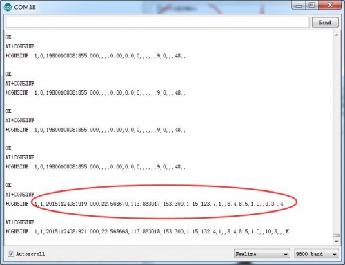
The result of get the GPS information.
