Crowtail- Hall Sensor
Description
The Crowtail- Hall Sensor uses the Allegro™ A1101 Hall-effect switches are next generation replacements for the popular Allegro312x and 314x lines of unipolar switches.It measures the Hall Effect, which is a production of a voltage difference across an electrical conductor, transverse to an electric current in the conductor as well as a magnetic field perpendicular to the current. The output of the continuous-time switch Hall sensor switches low(turns on) when a magnetic field (south polarity) perpendicular to the Hall sensor exceeds the BOP threshold, and it switches high( turn off) when the magnetic field disappears.
Model: CT0024HS
Features
- Crowtail Compatible Interface
- 400ns transition period for rise and fall.
- Continuous-time hall effect sensor
- Reverse battery protection
Specification
Dimensions(mm):20.0(L)x20.0(W)x6.8(H)
| Item | Min | Typical | Max | Unit |
|---|---|---|---|---|
| Voltage | 3.8 | 5.0 | 24 | V |
| Current | 4.1 | - | 24 | mA |
| Operating Temperature | -40 | - | 85 | ºC |
Usage
1.Hardware Connection
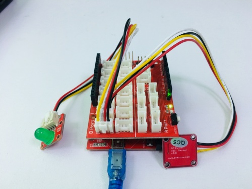
Connect the Hall Sensor to Digital port 4 of the Crowtail - Basic Shield using a 3 pin cable and connect Crowtail-LED to Digital Port 5.Then connect Arduino to PC by using a USB cable.
2.Upload the following sample sketch:
const int hall= 4;//PIN 4
const int led= 5;//PIN 5
void setup()
{
 pinMode(hall,INPUT);
 pinMode(led,OUTPUT);
}
void loop()
{
  if(digitalRead(hall)==LOW){
  digitalWrite(led,HIGH);
 }
 else{
 digitalWrite(led,LOW);
 }
 delay(500);
}
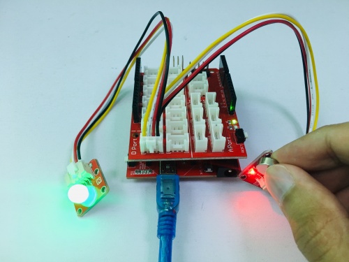
3.When the magnet near the hall sensor, the LED will light up. 


