CrowPanel 2.1inch-HMI ESP32 Rotary Display 480*480 IPS Round Touch Knob Screen
What is a rotary screen?
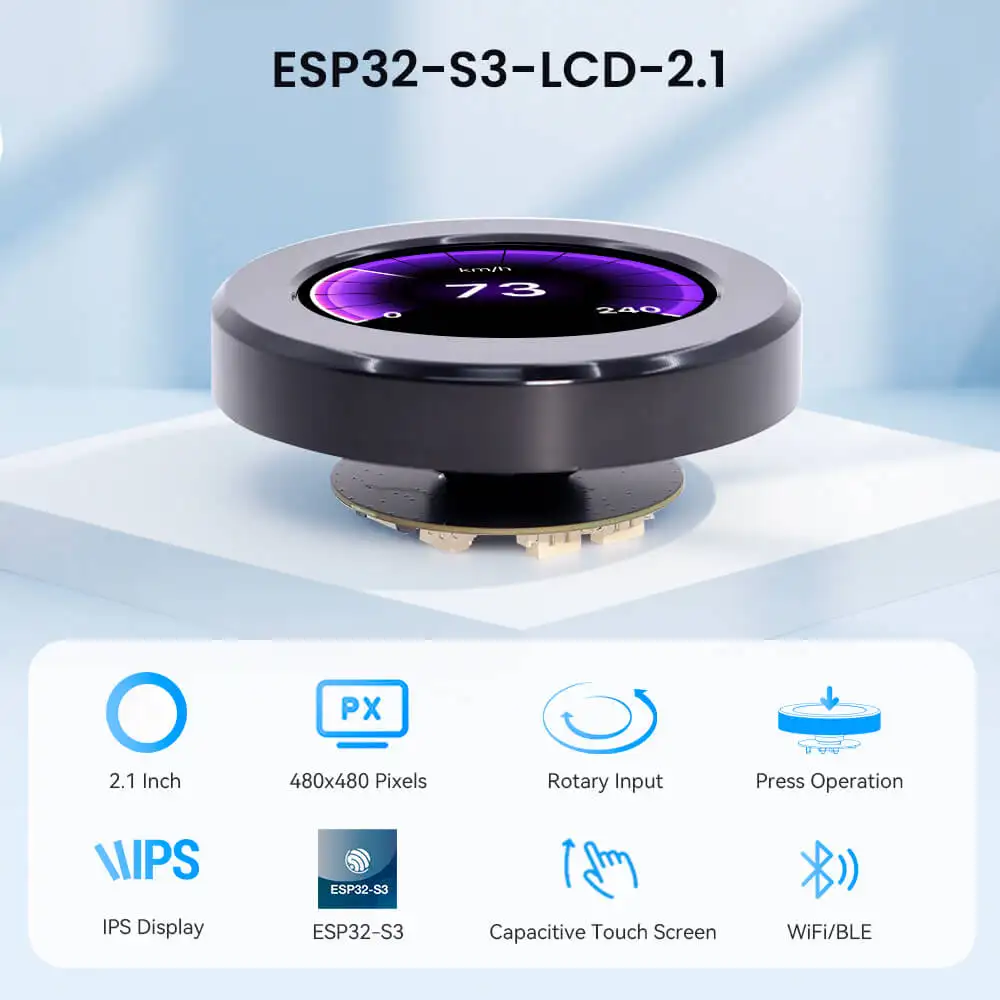
The rotary screen is an intelligent interactive device that usually consists of a circular knob and a display. The knob can be rotated to control various functions, while the display is used to display relevant information.
ESP32 Display - 2.1 inch rotary screen, uses high-performance ESP32-S3 chip, equipped with 32-bit dual-core chip. The maximum clock frequency reaches 240MHz, with strong performance and easy to handle complex tasks.
Supports 2.4G WiFi and BLE low-power Bluetooth, to achieve reliable wireless communication, easily connect to the Internet, suitable for smart home, industrial control, portable devices and other scenarios.
Supports capacitive touch operation and knob input, the knob supports clockwise, counterclockwise rotation and full press operation, smooth feel, and various interaction methods.
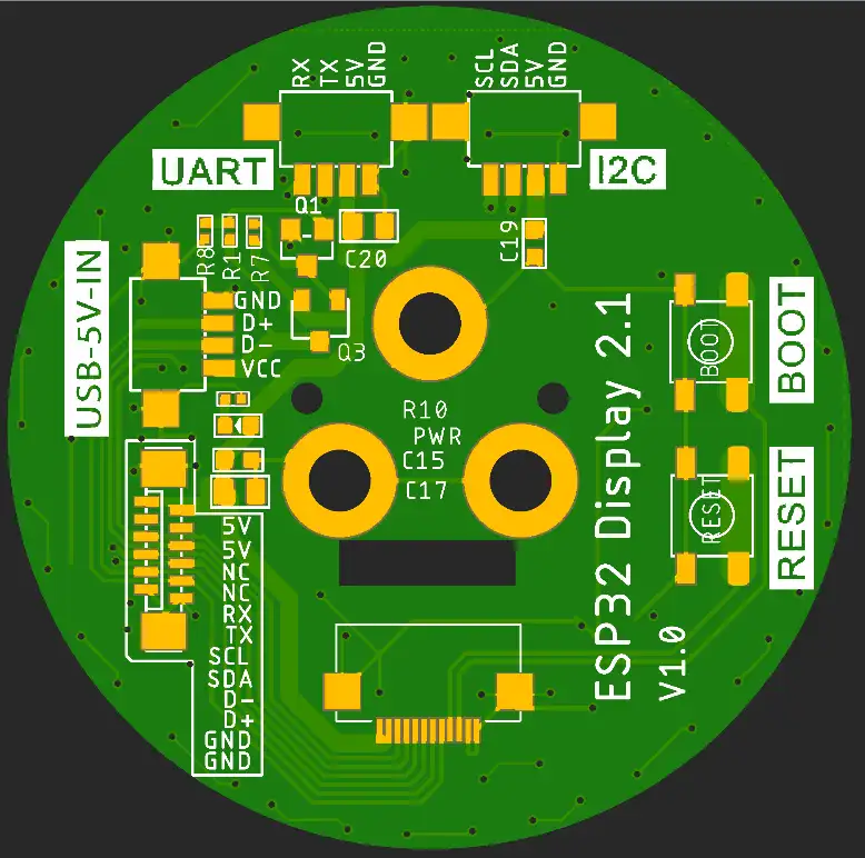
The 5V charging interface supports both power supply and program burning, and is also equipped with three expansion interfaces: UART, I2C, and FPC, to meet various development needs.
It supports Arduino IDE, Espressif IDF, Lua RTOS, Home Assistant/PlatformIO/Micro Python, and supports the LVGL library; you can design the UI interface yourself. It is an ideal platform for DIY projects like a mechanical keyboard knob.
ESP32 Display - 2.1 inch rotary knob screen is not just an interactive module, but an intelligent interaction solution that combines high performance, multi-function, and ease of use. Whether you are an IoT developer, smart home enthusiast, or professional, you can find an efficient tool that meets your needs.
Self-developed by Elecrow with exclusive design.
Model DHE03921D
Specification
| Main Chip: ESP32-S3R8 | |
|---|---|
| Processor | Equipped with high-performance Xtensa 32-bit LX7 dual-core processor, with a main frequency of up to 240MHz |
| System memory | 512KB SRAM、8M PSRAM |
| Storage | 16M Flash |
| Screen | |
| Size | 2.1 inch |
| Screen Type | IPS |
| Touch Type | Capacitive Touch |
| Resolution | 480*480 |
| Wireless Communication | |
| Bluetooth | Bluetooth Low Energy and Bluetooth 5.0 |
| WiFi | Support 802.11a/b/g/n,2.4GH |
| Hardware | |
| UART Interface | 1x UART1, 1x UART0; ZX-MX 1.25-4P |
| I2C Interface | ZX-MX 1.25-4P |
| FPC connector | 12P, Power supply burning port |
| Button | RESET button, BOOT button, confirmation button (knob press switch) |
| LED Light | Power indicator, LED ambient light |
| Other | |
| Power Input | 5V/1A |
| Operating temperature | -20~65℃ |
| Storage temperature | -40~80℃ |
| Operation Power | Module: DC5VMain Chip: 3.3V |
| Size | 79*79*30mm |
| Shell | Aluminum alloy + plastic + acrylic |
| Net Weight | 80g |
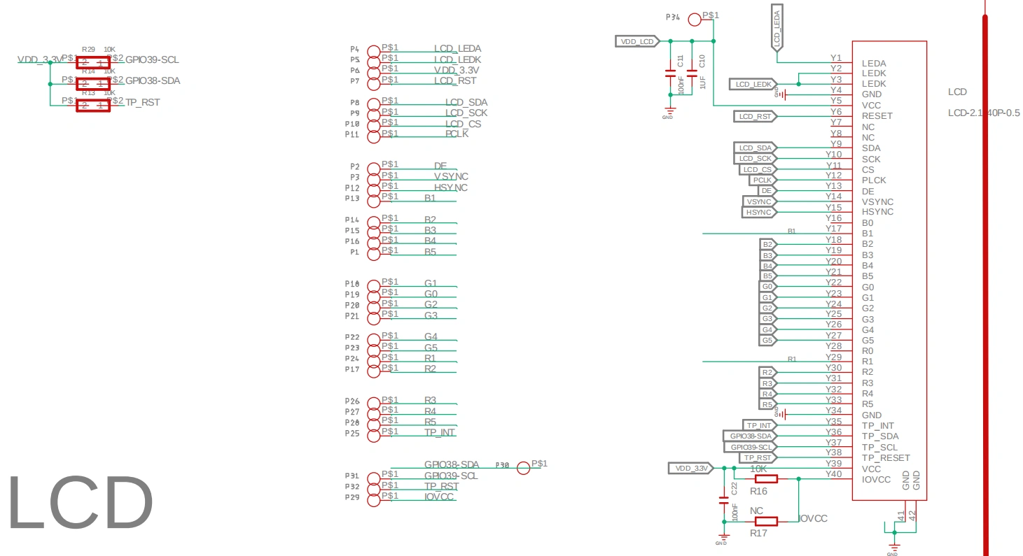
Schematic Diagram:
ESP32-S3 with display and touch schematic diagram
Schematic Diagram:
Definition in the main program:
Arduino_ESP32RGBPanel *bus = new Arduino_ESP32RGBPanel(
  16 /* CS */, 2 /* SCK */, 1 /* SDA */,
  40 /* DE */, 7 /* VSYNC */, 15 /* HSYNC */, 41 /* PCLK */,
  46 /* R0 */, 3 /* R1 */, 8 /* R2 */, 18 /* R3 */, 17 /* R4 */,
  14 /* G0/P22 */, 13 /* G1/P23 */, 12 /* G2/P24 */, 11 /* G3/P25 */, 10 /* G4/P26 */, 9 /* G5 */,
  5 /* B0 */, 45 /* B1 */, 48 /* B2 */, 47 /* B3 */, 21 /* B4 */
);

Arduino_ST7701_RGBPanel *gfx = new Arduino_ST7701_RGBPanel(
  bus, GFX_NOT_DEFINED /* RST */, 0 /* rotation */,
  false /* IPS */, 480 /* width */, 480 /* height */,
  st7701_type5_init_operations, sizeof(st7701_type5_init_operations),
  true /* BGR */,
  10 /* hsync_front_porch(10) */, 4 /* hsync_pulse_width(8) */, 20 /* hsync_back_porch(50) */,
  10 /* vsync_front_porch(10) */, 4 /* vsync_pulse_width(8) */, 20 /* vsync_back_porch(20) */);
-
I2C_SDA_PIN: 38
-
I2C_SCL_PIN: 39
-
ENCODER_A_PIN: 42
-
ENCODER_B_PIN: 4
-
SCREEN_BACKLIGHT_PIN: 6
PCF8574 Extended IO (via I2C address 0x21):
- P0:Touchscreen reset
- P2: Touchscreen interrupt
- P3: LCD power
- P4: LCD reset
- P5: Encoder button (INPUT_PULLUP)
Platforms Supported

| Arduino IDE | ESPHome |
|---|---|
 | |
 | |
Resource:
github:
CrowPanel-2.1inch-HMI-ESP32-Rotary-Display-480-480-IPS-Round-Touch-Knob-Screen
How to buy
Please visit this page to purchase CrowPanel 2.1inch-HMI ESP32 Rotary Display.
Support
If you have any problem about how to use it, you can connect to us at the bottom-right of bazzer or contact to techsupport@elecrow.com to get technology support.