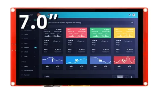
CrowPanel ESP32 HMI 7.0-inch Display
Module: DIS08070H

Updated Record
Please click on the "UPDATED RECORD" below to check the updated details in text.

Please watch below to check the updated explanation.
Feature
- Integrated ESP32-S3-WROOM-1-N4R8 module,built-in wireless communication 2.4 GHz Wi-Fi (802.11 b/g/n) and Bluetooth 5.0;
- Support development environment Arduino IDE, Espressif IDF, Lua RTOS, Micro python and compatible with LVGL graphics library;
- Built-in LVGL demo interface and Arduino example, plug and play;
- LCD 800*480 7.0 inch TFT-LCD with driver IC EK9716BD3 + EK73002ACGB;
- Rich peripheral interfaces and expansion functions enable it to meet the needs of different fields.
Specification
- Model: 7.0 inch ESP32 display
- Main Processor: ESP32-S3-WROOM-1-N4R8
- Resolution: 800*480
- Touch Type: Capacitive Touch Screen
- Display Type: TN Panel
- Screen: TFT-LCD Screen
- Display driver: EK9716BD3 & EK73002ACGB
- External power supply: DC 5V-2A
- Interface: 2 * UART0, 2 * GPIO, 2 * I2C,1*Battery
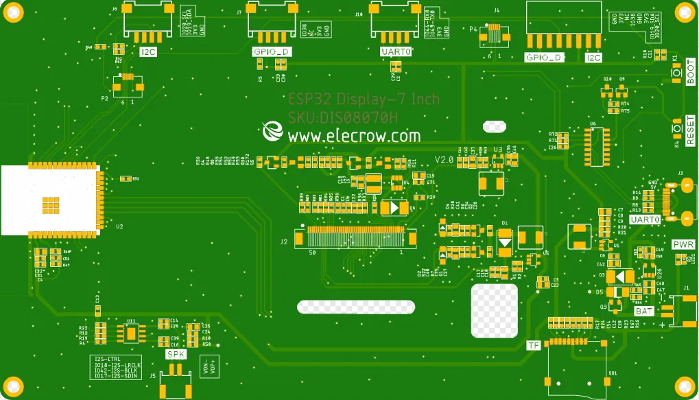
Pin Out
| Pin Name | Description | Connector Type |
|---|---|---|
| SPK | Output audio signal,connected with speakers. The motherboard comes with a power amplifier chip circuit. | PH2.0-2P |
| PWR | Power LED. | |
| RST | Reset button. Push it to reset the system. | |
| BOOT | ||
| GPIO_D | Digital and artificial I/O interface. | HY2.0-4P |
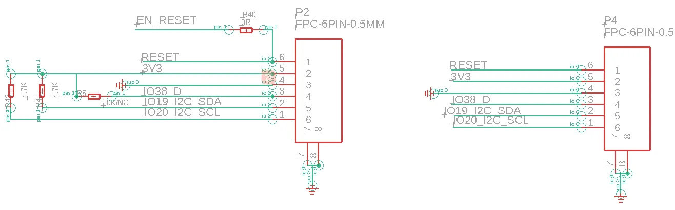
| I2C | Build the communication among micro controller and peripheral devices. | HY2.0-4P |
| TF | Provide off-line save and extra storage space. | |
| UART1 | Build the communication among Logic modules, including serial communication module and print module. | HY2.0-4P |
| BAT | Connect with the lithium battery. (With the battery charging circuit) | PH2.0-2P |
| UART0 | Provide serial communication, supply voltage(transform USB to UART0) and serial information printing. | HY2.0-4P/USB-C |
| 7.0-inch HMI Port | Pin Number |
|---|---|
| GPIO_D | IO38 |
| UART | RX(IO44); TX(IO43) |
| I2C | SDA(IO19); SCL(IO20) |
| SPK(I2S) | I2S-CTRL; I2S-LRCLK(IO18); I2S-BCLK(IO42); I2S-SDIN(IO17) |
| SD Card Slot(SPI) | MOSI(IO11); MISO(IO13); CLK(IO12); CS(IO10) |
| LCD Backlight | IO2 |
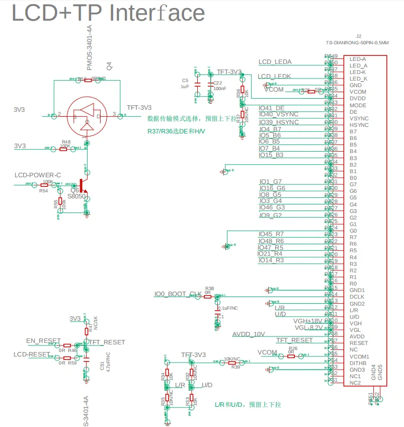
Schematic Diagram
ESP32-S3 and TFT display wiring pins
Schematic Diagram:
Definition in the main program:
class LGFX : public lgfx::LGFX_Device
{
public:

  lgfx::Bus_RGB     _bus_instance;
  lgfx::Panel_RGB   _panel_instance;

  LGFX(void)
  {


    {
      auto cfg = _bus_instance.config();
      cfg.panel = &_panel_instance;

      cfg.pin_d0  = GPIO_NUM_15; // B0
      cfg.pin_d1  = GPIO_NUM_7;  // B1
      cfg.pin_d2  = GPIO_NUM_6;  // B2
      cfg.pin_d3  = GPIO_NUM_5;  // B3
      cfg.pin_d4  = GPIO_NUM_4;  // B4

      cfg.pin_d5  = GPIO_NUM_9;  // G0
      cfg.pin_d6  = GPIO_NUM_46; // G1
      cfg.pin_d7  = GPIO_NUM_3;  // G2
      cfg.pin_d8  = GPIO_NUM_8;  // G3
      cfg.pin_d9  = GPIO_NUM_16; // G4
      cfg.pin_d10 = GPIO_NUM_1;  // G5

      cfg.pin_d11 = GPIO_NUM_14; // R0
      cfg.pin_d12 = GPIO_NUM_21; // R1
      cfg.pin_d13 = GPIO_NUM_47; // R2
      cfg.pin_d14 = GPIO_NUM_48; // R3
      cfg.pin_d15 = GPIO_NUM_45; // R4

      cfg.pin_henable = GPIO_NUM_41;
      cfg.pin_vsync   = GPIO_NUM_40;
      cfg.pin_hsync   = GPIO_NUM_39;
      cfg.pin_pclk    = GPIO_NUM_0;
      cfg.freq_write  = 15000000;

      cfg.hsync_polarity    = 0;
      cfg.hsync_front_porch = 40;
      cfg.hsync_pulse_width = 48;
      cfg.hsync_back_porch  = 40;

      cfg.vsync_polarity    = 0;
      cfg.vsync_front_porch = 1;
      cfg.vsync_pulse_width = 31;
      cfg.vsync_back_porch  = 13;

      cfg.pclk_active_neg   = 1;
      cfg.de_idle_high      = 0;
      cfg.pclk_idle_high    = 0;

      _bus_instance.config(cfg);
    }
            {
      auto cfg = _panel_instance.config();
      cfg.memory_width  = 800;
      cfg.memory_height = 480;
      cfg.panel_width  = 800;
      cfg.panel_height = 480;
      cfg.offset_x = 0;
      cfg.offset_y = 0;
      _panel_instance.config(cfg);
    }
    _panel_instance.setBus(&_bus_instance);
    setPanel(&_panel_instance);

  }
};


LGFX lcd;
ESP32-S3 and touch driver wiring
V2.0 Schematic Diagram:
Pin definition in the touch.h:
Tips:
Please refer to this post to check how to connect sensor using I2C pin and also use touch with it.
V3.0 Schematic Diagram:

Version 3.0 adds touch timing control based on Version 2.0 to prevent touch failures. When writing programs, you need to build upon the Version 2.0 program to implement the timing control logic.
PCA9557 Out;
Out.reset();
Out.setMode(IO_OUTPUT);
Out.setState(IO0, IO_LOW);
Out.setState(IO1, IO_LOW);
delay(20);
Out.setState(IO0, IO_HIGH);
delay(100);
Out.setMode(IO1, IO_INPUT);
Platforms Supported
| Arduino IDE | SquareLine Studio | PlatformIO |
|---|---|---|
 | ||
 | | |
| MicroPython | ESP-IDF | Home Assistant |
|---|---|---|
| | |
| ESPHome |
|---|
 |
|


FAQ
- Click here to see the frequently asked questions of ESP32 display.
- Please list your question at the forum or contact techsupport@elecrow.com for technology support.
Resources
Github Link
(This GitHub link usually may contain 3D files, schematics, program code, factory firmware, factory sourcecode and other materials. Please click to view.)
Schematic & PCB
Specifications
Certification
- CrowPanel CE Certificate
- ESP32-S3-WROOM-1 Wi-Fi Certification
- ESP32-S3-WROOM-1 NCC Certification
- ESP32-S3-WROOM-1 IC Certification.pdf
- ESP32-S3-WROOM-1 MIC Certification.pdf