Lesson5 SD card stores images and displays them locally
Welcome to the application tutorial of Lesson 5.
The effect to be achieved in this lesson is to store the images that need to be displayed on the SD card and display them on the CrowPanel ESP32 Advance HMI AI Display.
This lesson requires everyone to prepare an SD card to store pictures. And a card reader.
1 Select the photos you want to display on the browser and save them on the desktop (the save path can be customized)

You can download the sample images we provide:
2 Modify the resolution of the image based on the size of the product you are using.
This is the resolution size we accept for each size product.
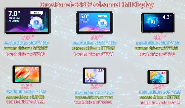
Here, for large-sized products, I will take the 7.0-inch product as an example to introduce how to modify the resolution of images.
The resolution of the 7.0-inch / 5.0-inch / 4.3-inch product is 800*480.
(Note: The image resolution of 7.0-inch, 5.0-inch, and 4.3-inch products is consistent, and the code and image can be used interchangeably.)
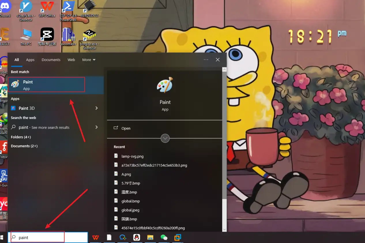
First, open the "paint" tool on the computer.
Drag and drop the image into the "paint" tool to readjust the pixels of the image
(Images can be uploaded to the browser and selected according to everyone's preferences)


Adjust the pixel to 7.0-inch screen resolution: 800x480
Can be referred to:There are resolutions of different sizes as references above. (Second point)

Remember to save.
Save to a folder for easy use (folder path can be customized)
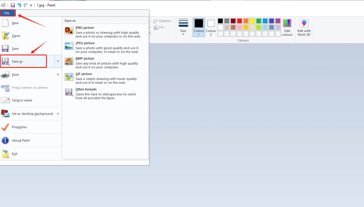
Save in BMP format (must have a 24 bit image depth)

Insert the SD card into the card reader

Open the SD drive, copy the modified image to the SD drive and save it
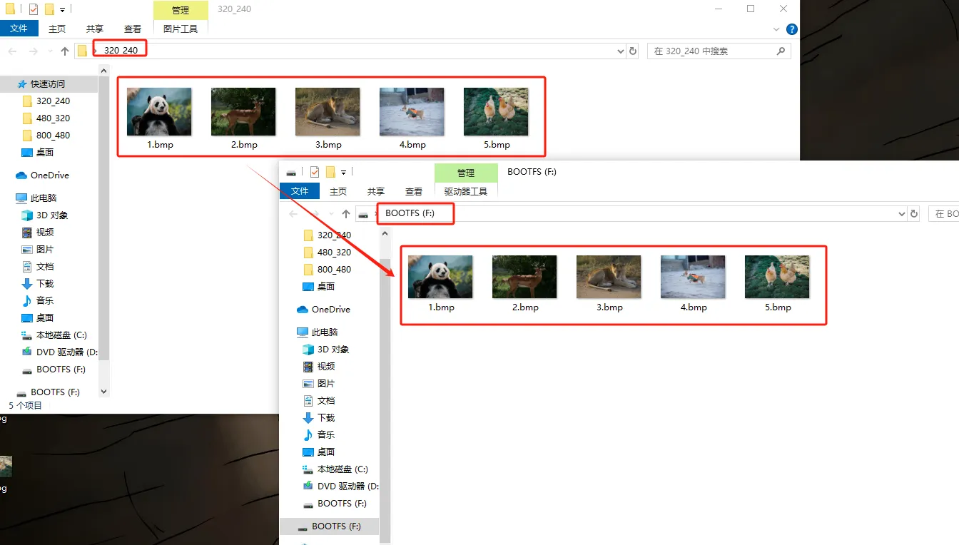
Exit the SD card and remove the SD card
3 Insert the SD card containing this saved image into your CrowPanel ESP32 Advance HMI
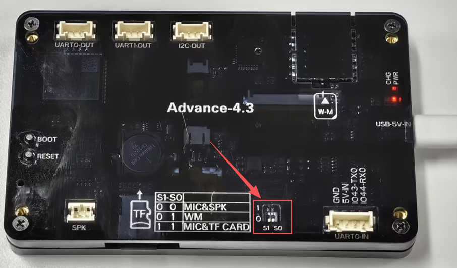
Insert the SD card into the TF card slot, provided that you have already placed the correct pictures inside it.

(2.4-inch,2.8-inch,3.5-inch products can be directly inserted for use)
After inserting the SD card, turn the function switch to 1 1 mode (TF Card mode) for 7.0-inch, 5.0-inch and 4.3-inch.
4 Open the code we provide
Code download link:

Download it to the Desktop and Open it with VS Code

This project is developed and run on ESP-IDF version 5.5.4.
First, you need to specify the version of the arduino-esp32 component in the idf_component.yml file under the main folder. In this project, version 3.3.10 is used to ensure compatibility with ESP-IDF 5.5.4. After the configuration is completed, the ESP-IDF build system will automatically download and integrate the specified Arduino framework version during the first compilation.
This setup allows the project to combine the ESP-IDF development environment with the Arduino programming interface, enabling the use of Arduino-style APIs within an ESP-IDF-based project.

This section includes all the required project libraries. LovyanGFX_Driver.h provides a high-performance LCD display driver with support for double buffering, hardware DMA acceleration, and independent display rotation. Wire.h enables I2C communication and is used to control the display backlight and the touch controller at I2C address 0x30. SPI.h, FS.h, and SD.h implement high-speed SPI communication and the SD card file system, allowing image files to be read directly from the SD card. Finally, esp_heap_caps.h is an ESP32-specific memory management API that allocates large image buffers from external PSRAM (SPIRAM), preventing internal RAM overflow when processing high-resolution images such as 800 × 480.

This section centralizes all hardware and application parameters used by the project.
- Display Configuration: The display resolution is set to 800 × 480. Since a single 24-bit BMP image occupies a large amount of memory, external PSRAM is required to store the image buffer.
- Dedicated HSPI Pins for the SD Card: The SD card uses an independent HSPI interface with MOSI = GPIO6, MISO = GPIO4, SCK = GPIO5, and CS = GPIO0. This separates the SD card from the display SPI bus, preventing bus conflicts and display corruption.
- Image Display Timing and Read Optimization: Each image is displayed for 5000 ms. The SD card is read in blocks of up to 32,768 bytes per transaction, reducing SPI latency and improving image loading performance.
- Image Resource Management: All BMP image paths are stored in a single array.
IMAGE_COUNTautomatically calculates the total number of images, so images can be added or removed without manually updating the count.IMAGE_PIXEL_BYTEScalculates the total number of bytes required for the RGB888 pixel data of a single image. - Independent Display Rotations:
kUiRotation = 0defines the rotation used for the text-based user interface, whilekImageRotation = 2defines the rotation used for full-screen image display. Using separate rotation settings allows the UI and images to be displayed with different orientations without affecting each other.

This section defines the global shared resources used throughout the project.
- Global Hardware Objects:
SD_SPIis a dedicated HSPI instance used exclusively for SD card communication, ensuring that the SD card does not share the SPI bus with the display.gfxis the global display driver object responsible for all screen drawing operations. - Image Buffer Array:
imageSlotsis an array of pointers that stores the PSRAM addresses of all five preloaded images. By loading all images into memory at startup, the program can render them directly from PSRAM during playback without repeatedly accessing the SD card, resulting in smoother image transitions. - Current Image Index:
showIdxrecords the index of the image currently being displayed. It is incremented cyclically to implement continuous image slideshow playback. - Image Loading Status:
allImagesLoadedis a global status flag that indicates whether all images have been successfully loaded from the SD card. It is set totrueonly after every image is loaded successfully. If loading fails, the program continues displaying an error message on the screen and does not enter slideshow mode.

This section implements a utility function for displaying centered status messages on the screen. It always uses the UI rotation setting (kUiRotation = 0) to ensure a consistent display orientation. The function first acquires the SPI bus, clears the screen by filling it with black, and then automatically calculates the text position to center it both horizontally and vertically. It also supports customizable text colors, with red used as the default. This function provides a unified interface for displaying status messages such as SD card mounting, image loading progress, and error notifications, ensuring a consistent user experience throughout the application.

This section allocates large image buffers for all five images in external PSRAM, providing enough memory to store high-resolution image data efficiently. The implementation includes several key optimizations:
- Avoid Duplicate Allocation: Before allocating memory, the function checks whether a buffer has already been assigned, preventing repeated memory allocation and unnecessary memory usage.
- Allocate Memory from External PSRAM:
heap_caps_malloc()is called with theMALLOC_CAP_SPIRAMcapability, ensuring that the image buffers are allocated from external PSRAM instead of the ESP32's limited internal RAM. This prevents memory overflow when processing large 800 × 480 images. - 8-Bit Accessible Memory: The
MALLOC_CAP_8BITcapability guarantees that the allocated memory is 8-bit addressable, making it fully compatible with RGB888 pixel data operations. - Allocation Failure Handling: If memory allocation fails for any image buffer, the function prints an error message to the serial monitor, returns
false, and immediately terminates the image loading process to prevent subsequent runtime errors.

This section handles reading a single 24-bit standard BMP image from the SD card and writing it into the PSRAM buffer in blocks. The implementation is optimized as follows:
- File Validation: The function first opens the image file and checks its validity. If the file cannot be opened, or if its total size is smaller than 54 bytes (BMP header + pixel data), it is considered corrupted and the function returns a failure status immediately.
- Skip BMP Header:
f.seek(54)is used to skip the standard 54-byte BMP header, directly positioning the file pointer at the start of the RGB pixel data. - Chunked Reading Strategy: The image data is read in chunks, with a maximum block size of 32,768 bytes per read operation. This prevents long SPI blocking and improves system stability. Each chunk is written into the target PSRAM buffer, and a short delay is introduced after each read to release the SPI bus.
- Integrity Check: If the number of bytes read does not match the expected value, the SD card read operation is considered corrupted. The file handle is closed and the function returns
false. - Successful Completion: If all data is read correctly and written into PSRAM, the file is closed and the function returns
true, indicating that the image has been successfully cached.

This section implements a full preloading process that loads all images from the SD card into PSRAM before entering the slideshow mode. The workflow is as follows:
- Memory Allocation Check: The system first calls the PSRAM allocation function. If memory allocation fails, the process is immediately terminated to prevent further errors.
- Loading UI Prompt: A centered yellow status message, “Loading images...”, is displayed on the screen to indicate that image resources are being loaded.
- Batch Image Loading: The system iterates through all image paths and prints the loading progress via the serial monitor. Each image is loaded one by one into its corresponding PSRAM buffer. If any image fails to load, the process is immediately aborted and
falseis returned. - Successful Completion: If all images are successfully loaded, the function returns
true, and the global flagallImagesLoadedis set totrue, allowing the system to transition into slideshow playback mode.

This section implements direct rendering of images from preloaded PSRAM buffers to the display, using LovyanGFX double-buffering technology to improve visual smoothness and eliminate tearing.
- Switch to Image Display Mode: The system first switches to the dedicated image rotation setting (
kImageRotation = 2). At the same time, the display enables double-buffer rendering, where the full image is drawn into the back buffer before being shown on screen. - Full-Screen SPI Transfer: The SPI bus is locked to ensure uninterrupted transmission. The system then pushes the complete RGB888 image data from PSRAM to the display in one batch, rendering it from the top-left corner to fill the entire screen.
- Double Buffer Commit: Calling
commitBackBuffer()refreshes the entire screen in a single operation. This eliminates tearing artifacts caused by line-by-line rendering and ensures smooth image display. - Restore UI Mode: After rendering is complete, the system switches back to the UI rotation setting (
kUiRotation = 0). This ensures that subsequent status messages and UI elements are displayed correctly without affecting the image rendering mode.

This section describes the full hardware initialization sequence executed at system power-on, with a strictly layered startup order to ensure stability.
- Serial Logging Initialization: The system first enables the UART serial port at 115200 baud rate and prints a boot log to indicate system startup.
- Display Initialization: The LovyanGFX display driver is initialized, the UI rotation is set to 0 (text mode), and the screen is cleared to black. A 500 ms delay is added to ensure display hardware stabilization.
- I2C Peripheral Initialization: The I2C bus is initialized with SDA = GPIO15 and SCL = GPIO16. A command is sent to the device at address 0x30, which is used to enable the display backlight and touch controller.
- SD Card Initialization and Image Loading:
- If SD initialization is successful, a green status message is displayed indicating normal operation, followed by a 1-second delay, and then all images are preloaded into memory.
- If image loading fails, a red error message is displayed.
- If SD initialization fails, a red warning message is shown indicating SD card failure.
- Final Initialization Stage: After a final 500 ms delay, the screen is cleared, a completion log is printed, and the system enters the image slideshow loop.

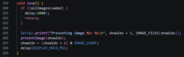
This section describes the main infinite loop slideshow logic, which controls image rendering and switching behavior.
- Loading State Check: The system first checks whether all images have been fully loaded into PSRAM. If loading is not complete, the loop enters a low-frequency wait mode, sleeping for 2 seconds per cycle without performing any rendering operations.
- Image Rendering: Once all images are successfully preloaded, the system logs the current image index and calls
presentImage()to render the image directly from the PSRAM cache to the display in full-screen mode. - Index Cycling Logic: The image index is incremented using a modulo operation, ensuring continuous looping playback. Each image remains on screen for a fixed duration of 5000 ms (5 seconds) before switching to the next image.
- Performance Optimization: Since all images are stored in PSRAM, switching images does not require accessing the SD card again. This eliminates SPI read delays and ensures smooth, glitch-free transitions with no visible lag during playback.
5 Configure the runtime environment and burn code
Click the link below and you can access the code for this lesson.
Code Link:
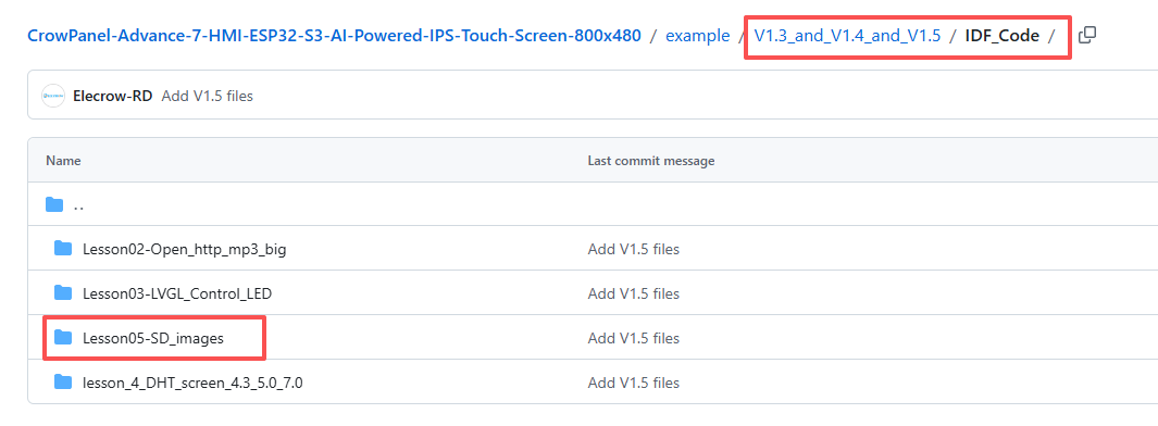
Select the code folder for this lesson, right-click on it, and then choose to open it with VS Code.
Note:
Remember to prepare the hardware environment as per the first point of this course.
Then, following Step 5 “Run the program” from Lesson 1, upload and execute the code in the correct sequence.
Please proceed in the following order: 1 → 2 → 3 → 4 → 5 → 6 → 10

After uploading the code, the display will automatically cycle through and show each image stored on your SD card. Simply make sure that the image filenames on the SD card match the filenames specified in the code.
6 Phenomenon display
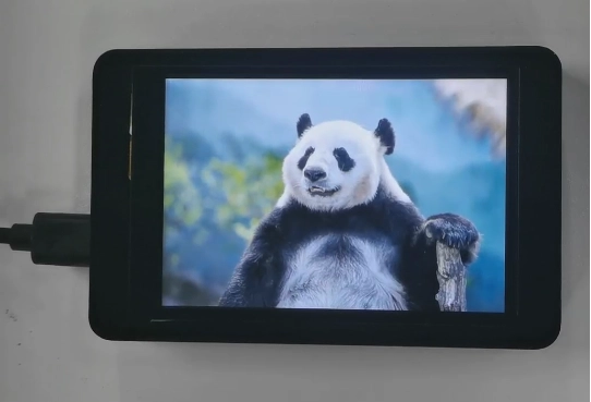

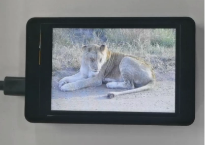
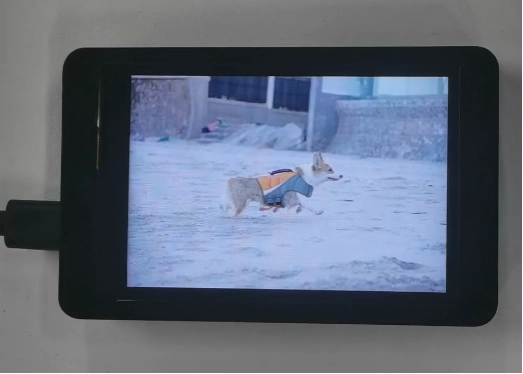
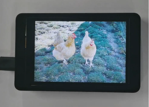
The five photos I saved on the SD card will be displayed in a loop.
Kind Reminder:
You are currently viewing the 7-inch product of CrowPanel Advance HMI AI Display, and the version here is V1.3 / V1.4 / V1.5.
(For the 4.3-inch V1.1 / V1.2 / v1.3 version and the 5.0-inch V1.2 / v1.3 version, the following information also applies.)
In terms of hardware, we use a microcontroller (STC8H1K28) to control the screen backlight, speaker on/off, and buzzer.
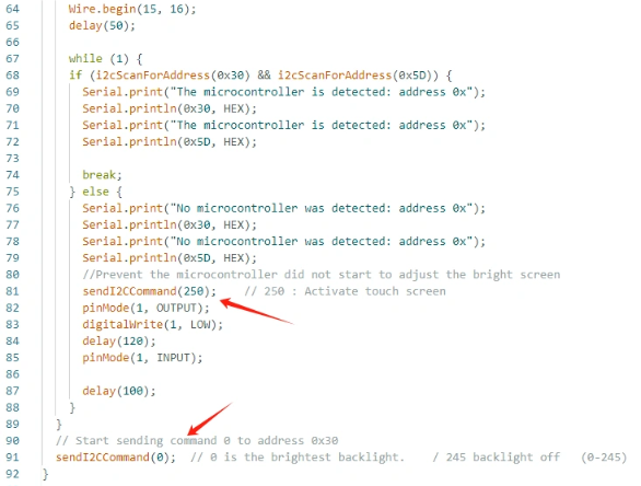
(However, there are other function interfaces that need to be written in the specific code, and you can refer to the complete code provided later.)
Explanation:
-
0x30 is the I2C address of the microcontroller (STC8H1K28).
-
0x5D is the I2C address of the touch IC (GT911).
-
sendI2CCommand(0) means sending command 0 to the microcontroller (address 0x30) to instruct it to set the screen brightness to maximum.
For 0 mentioned above, you can replace it with the following values:
- 0 is the brightest backlight.
- 0 to 245: The screen brightness will gradually increase to the minimum value
- 245 represents turning off the screen light
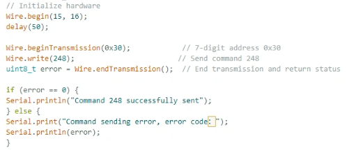
Additional notes:
You can also control the following functions by sending other instructions to the microcontroller:
- It means sending the 248 command to the microcontroller (0x30) to instruct the speaker to turn on.
- It means sending the 249 command to the microcontroller (0x30) to instruct the speaker to turn off.
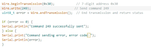
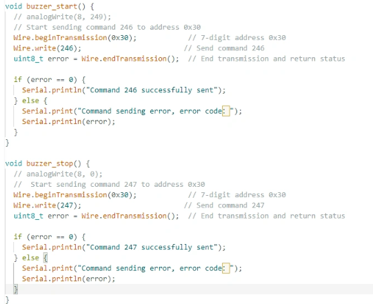
- You can also send command 246 to control the buzzer to turn on, and send command 247 to control the buzzer to turn off.