Lesson4 The temperature and humidity sensor receives data in real time
Welcome to the Lesson 4 of learning.
This lesson will use the IIC interface and of this series of products to collect data from temperature and humidity sensors. In this lesson, we will use the knowledge of LVGL graphics library from Lesson 3 to create an interactive interface.
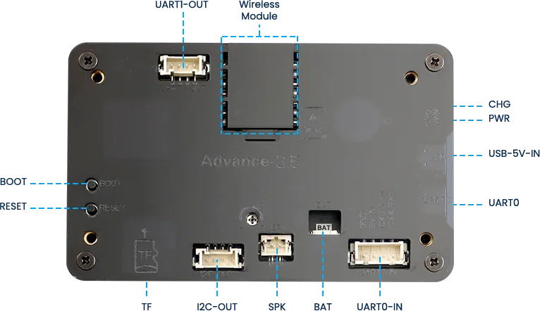
1. Introduce product ports
USB interface: used for power supply, serial communication, and automatic programming.
UART0-IN interface: supports power supply, serial communication, and entering manual burning mode by pressing BOOT+RESET; Other functions are consistent with the USB interface.
UART0-OUT interface: used for external power supply and serial communication.
UART1-OUT interface: uses soft serial port and supports configuring IO function.
I2C-OUT interface: connects RTC chip, extended IO chip (for screen backlight, touch screen reset, power amplifier pin control) and wireless module, only supports I2C communication.
2. UI interface design
The temperature and humidity sensor needs to support IIC communication.
In order to provide everyone with an intuitive observation, I will use LVGL to create an interactive interface.
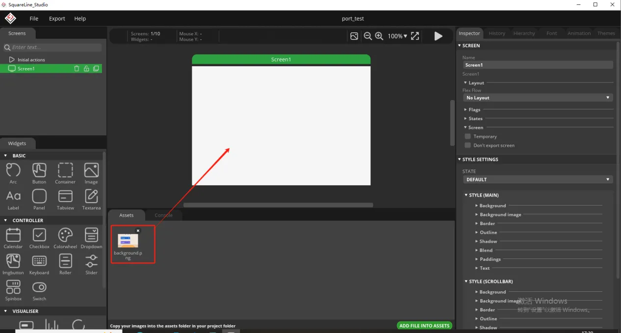
Open SquareLine Studio. If you haven't installed it, you can review the introduction of LVGL in Lesson 3.
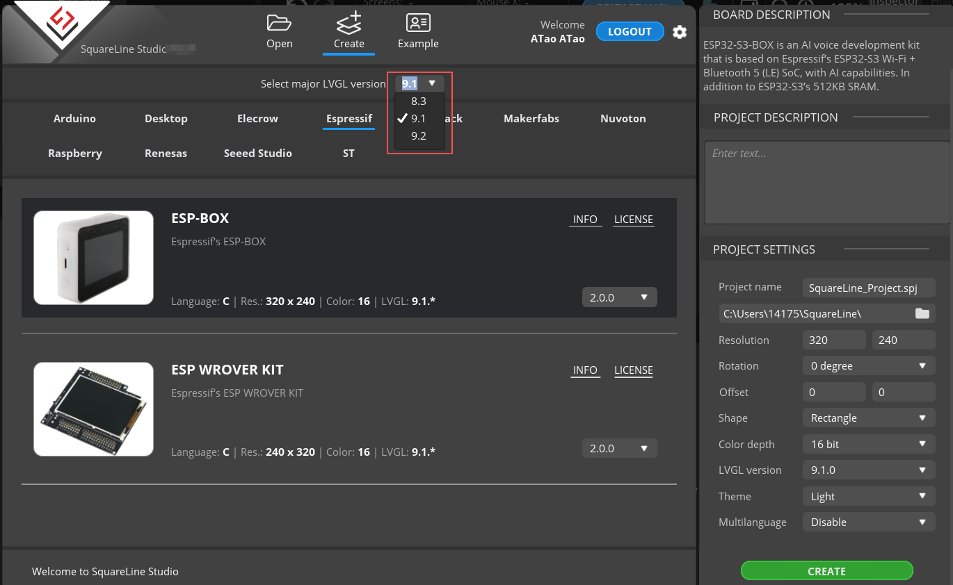
Create "Espressif" project
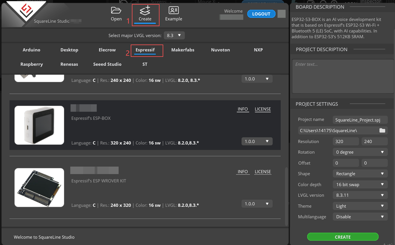
Note: For this lesson project, use LVGL v9.1.0 for 2.4-inch and 2.8-inch devices.
For 3.5-inch, 4.3-inch, 5.0-inch, and 7.0-inch devices, use LVGL v8.3.11.
Modify the file name and file storage path according to your needs (customization is sufficient)
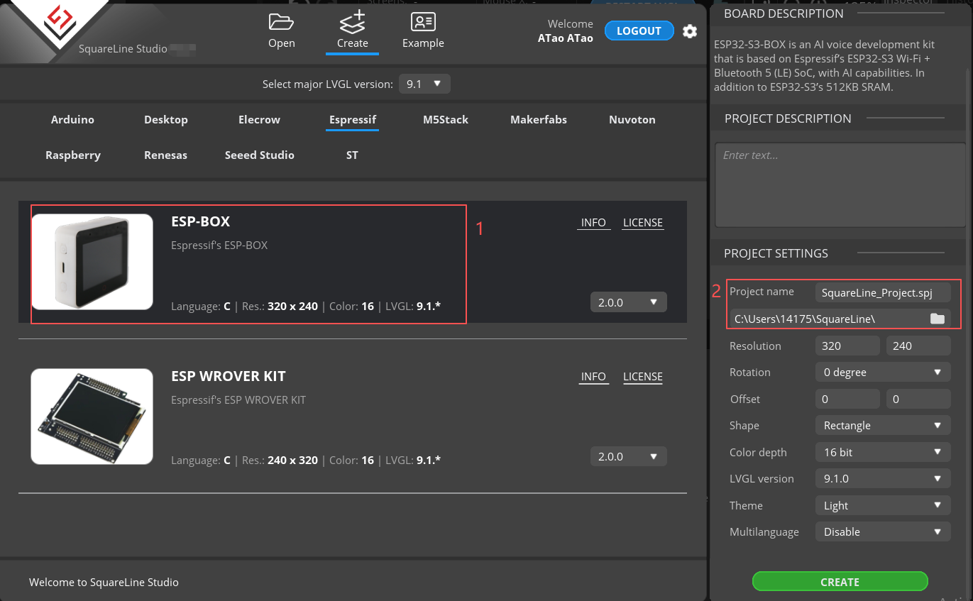
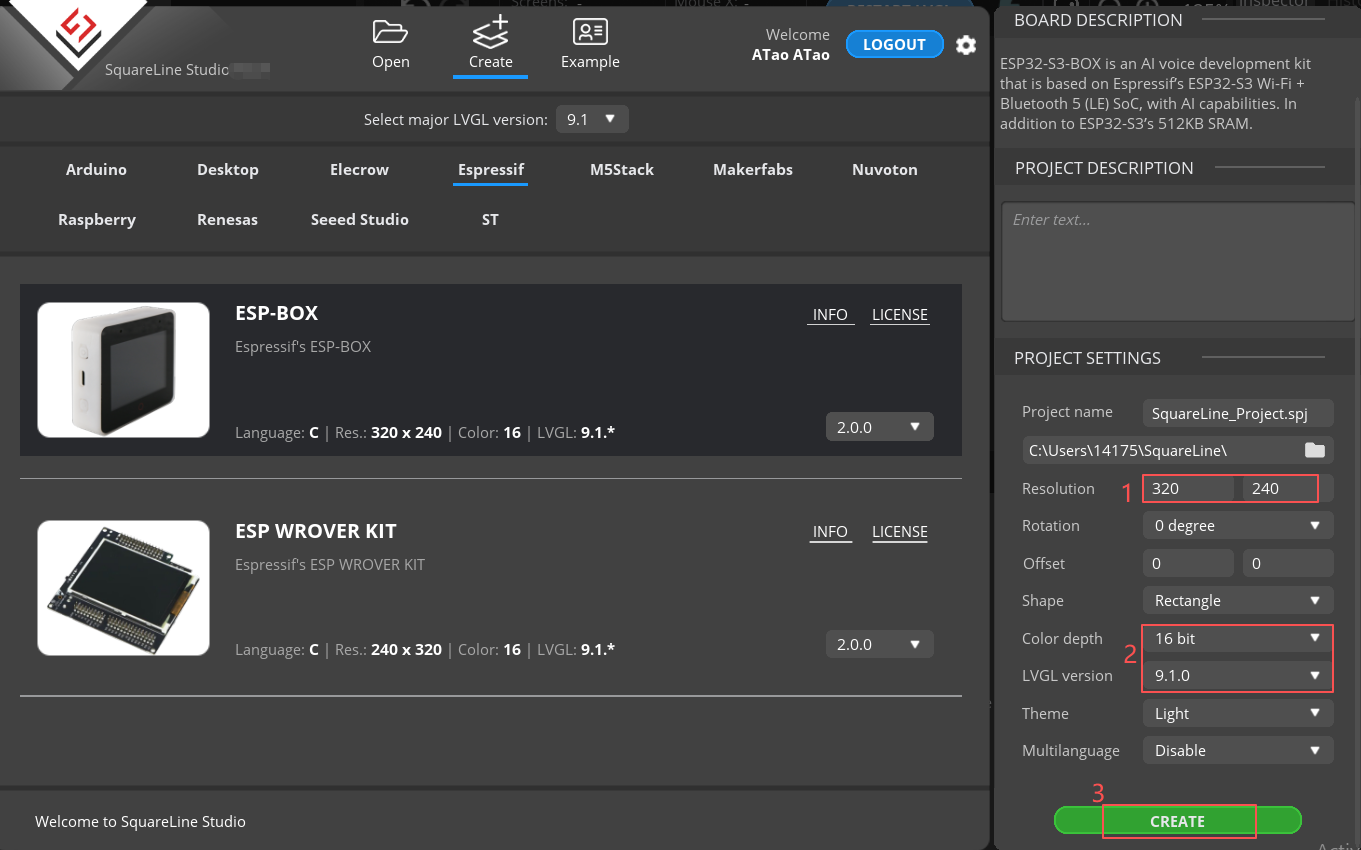
Modify the appropriate resolution based on the different sizes you are using.
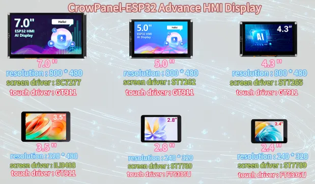
If you are using the 4.3-inch, 5.0-inch, or 7.0-inch version of the product, you will need to set the display resolution to 800 × 480, according to the size comparison chart shown above.
Please note that this project uses the LVGL 8.3.11 version. Make sure to configure the correct LVGL version to ensure compatibility with the provided code and examples.
Finally, click on 'Create' to proceed.
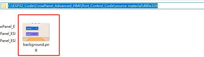
Add the background image we provide based on the resolution required for the size you are using (choose different resolutions for different sizes, refer to the resolution size used for different sizes in Lesson 3)
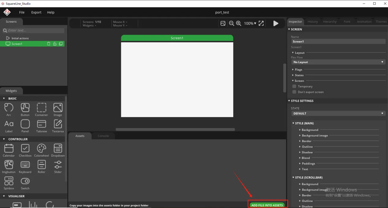
Here is the corresponding image asset download link for each screen size:
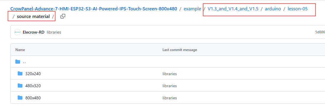
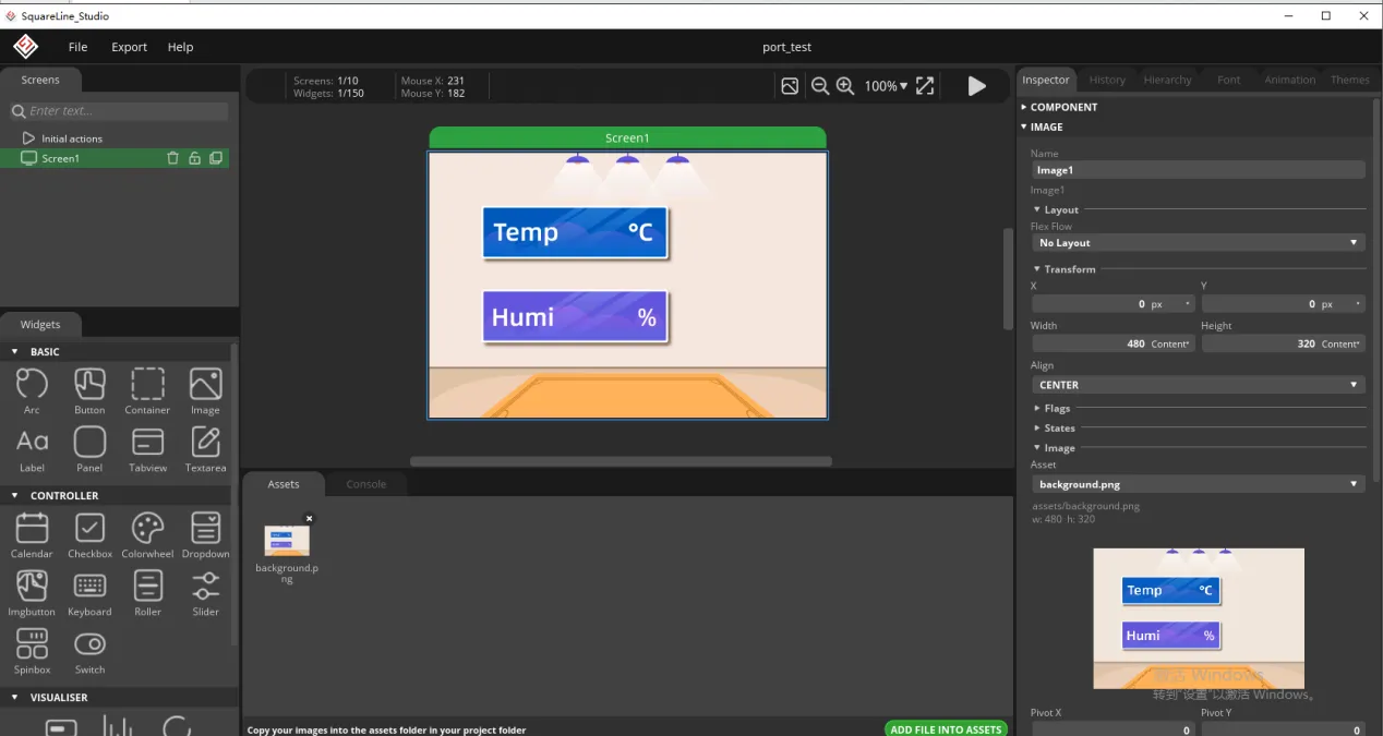
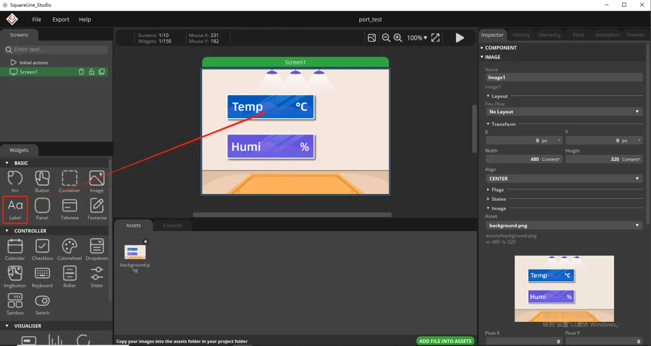
Add background image to the box.
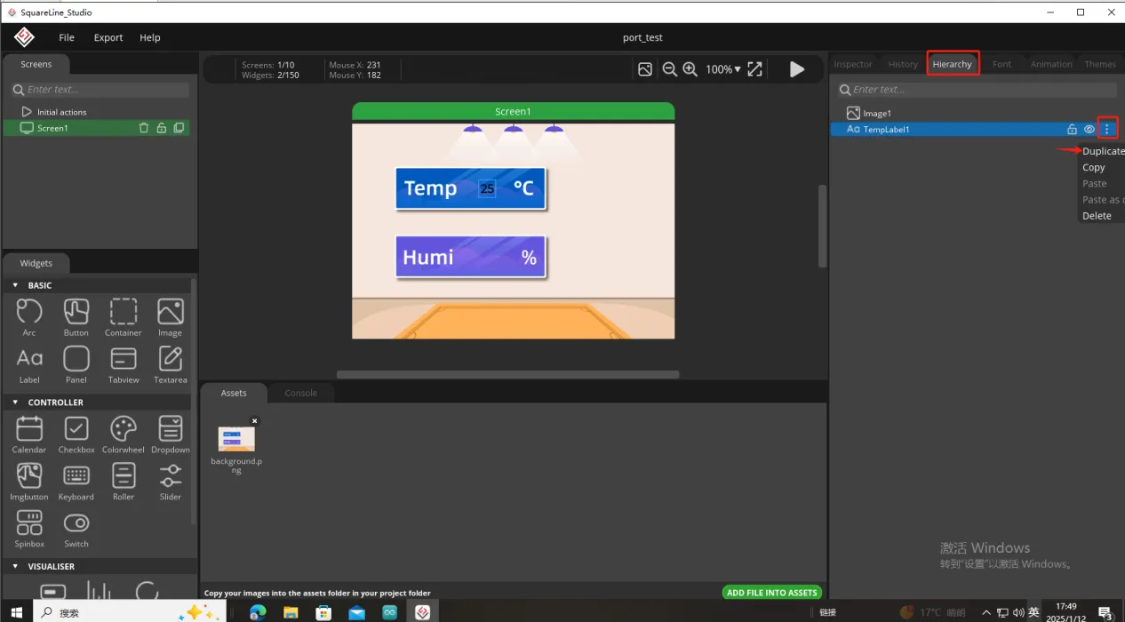
Since we need to display the temperature and humidity values on the screen, we need to add text in the two boxes for temperature and humidity.
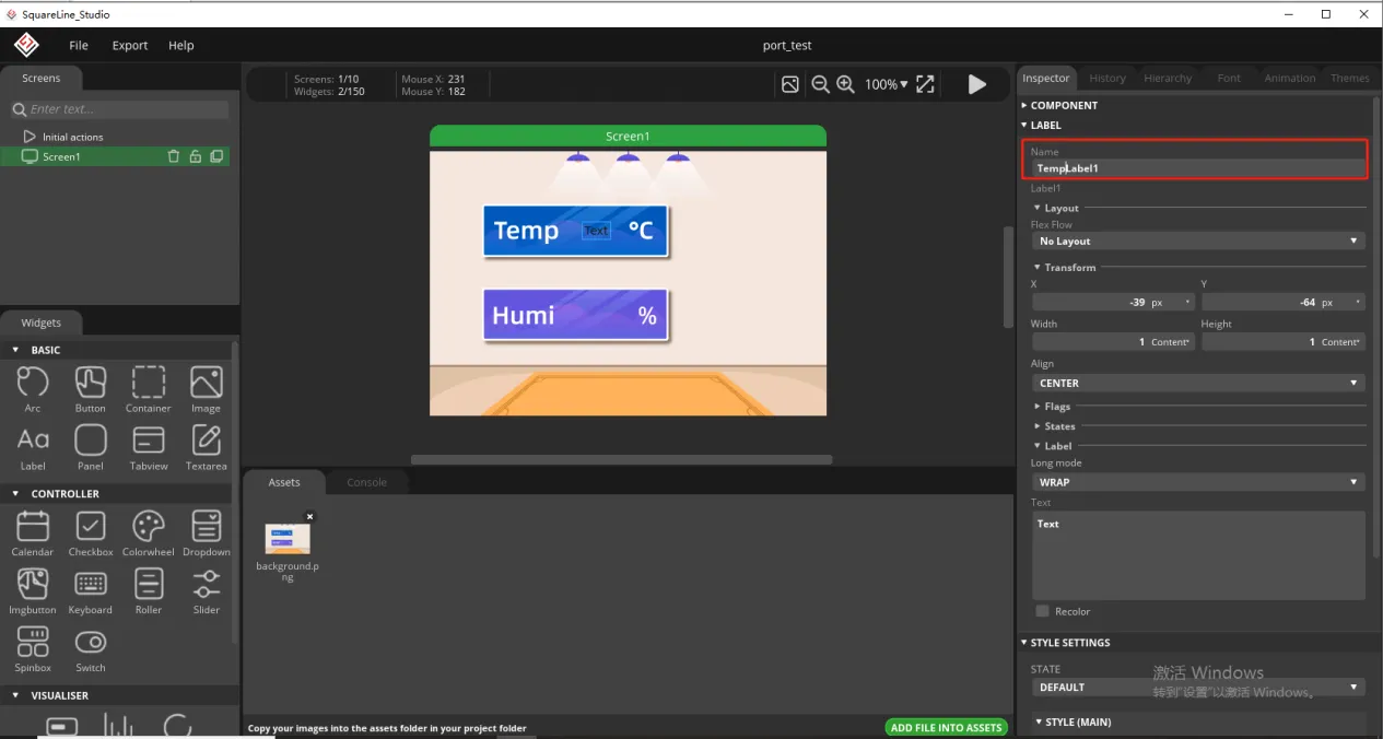
To distinguish between the other text labels that need to be created next, give this label a name to distinguish it.
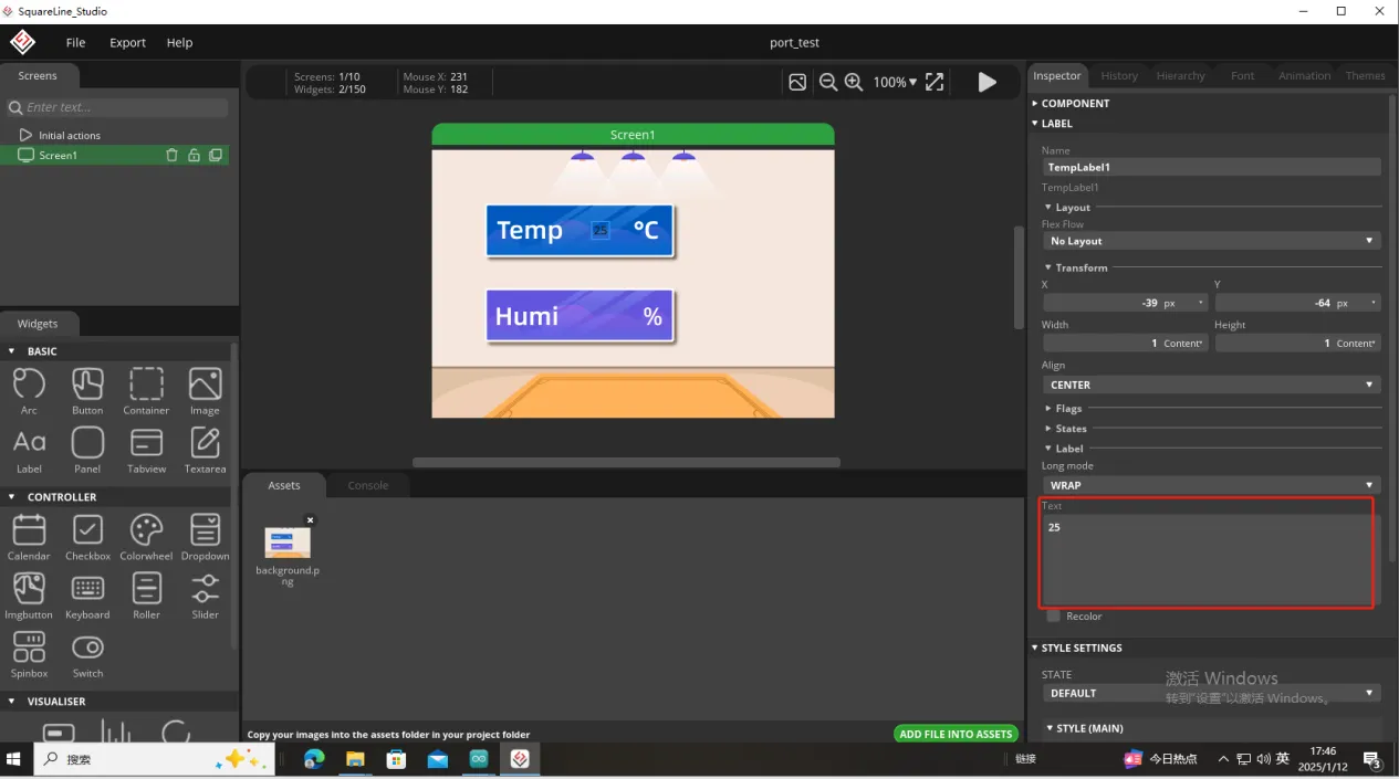
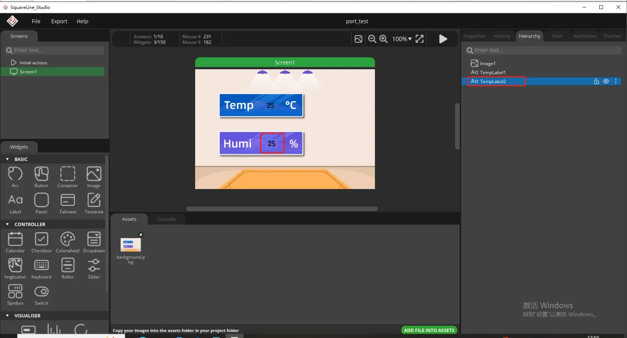
And fill in a default temperature value
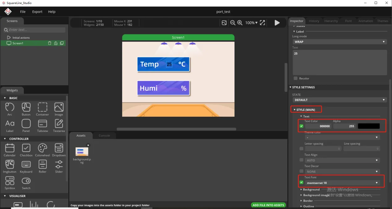
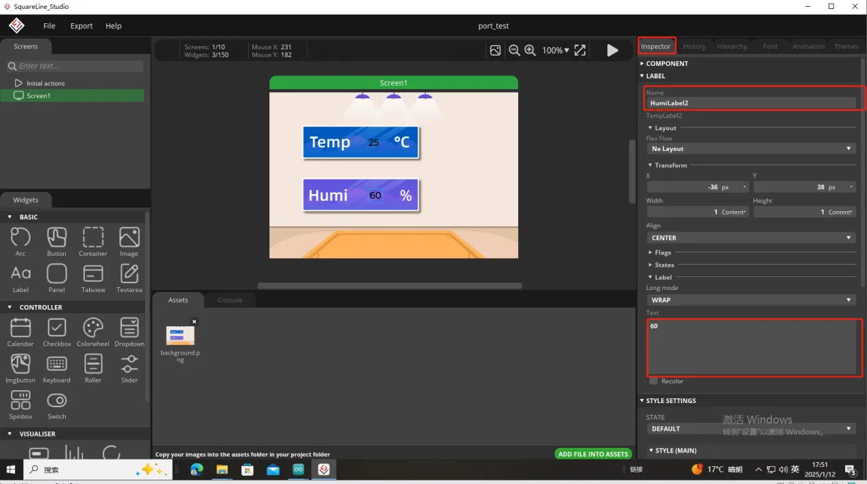
Of course, you can also set the font color and font size here
Copy the label just made and display the humidity value
Follow the above steps to modify the humidity label
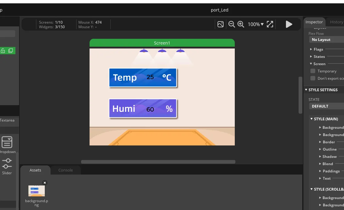
In this way, the display of temperature and humidity is completed.
So, the UI interface we need is completed.
Export the designed UI interface file
How to set the specific export path, please refer to the previous lesson.
Go to the folder path where you selected to output the UI file.

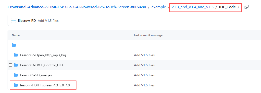
Click the link below and you can access the code for this lesson.
Code Link:
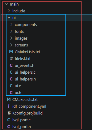
Next, open the project folder provided for this course using VS Code. Then, copy the .h and .c files generated by LVGL into the corresponding ui folder of the project.
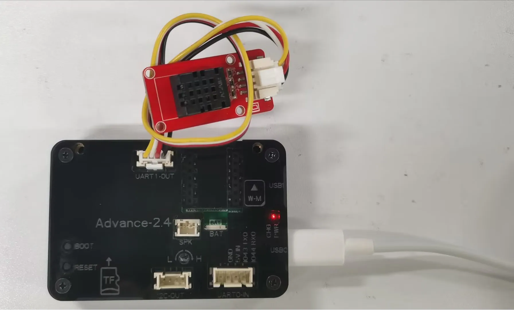
3. Hardware connection
Connect the temperature sensor to the development board and power on the development board.
Note: For the 2.4-inch and 2.8-inch development boards, connect the temperature sensor to UART1-OUT. For other sizes, connect it to I2C-OUT.
Special Reminder:(The following applies only to 2.8-inch and 2.4-inch products)
The IIC address of the 2.8 and 2.4 touch driver ICs is 0x38, and the IIC address of the DHT20 temperature and humidity sensor is also 0x38. When the DHT20 temperature and humidity sensor is connected to the IIC-OUT interface for use, the two addresses conflict, causing abnormal device usage. The DHT20 temperature and humidity sensor will no longer work, but will ensure the driving of the touch IC.
So in order to make the DHT20 temperature and humidity sensor work, we can connect the DHT20 temperature and humidity sensor to UART1-OUT.
Special note: The UART1-OUT interface allows the use of two or fewer IO interfaces, namely 17 and 18 pins, for your convenience. For example, when connecting a light bulb, 18 pins can be used to receive the initiated control signal. For example, doing digital input/output and analog input/output. There are also some infrared receivers, buzzers, and lights that can be connected. The premise is that you should not use more than 2 IO ports, such as SPI, which requires four IO ports to control and cannot be used.
4. Explanation of the code project
This project is developed and run on ESP-IDF version 5.5.4.
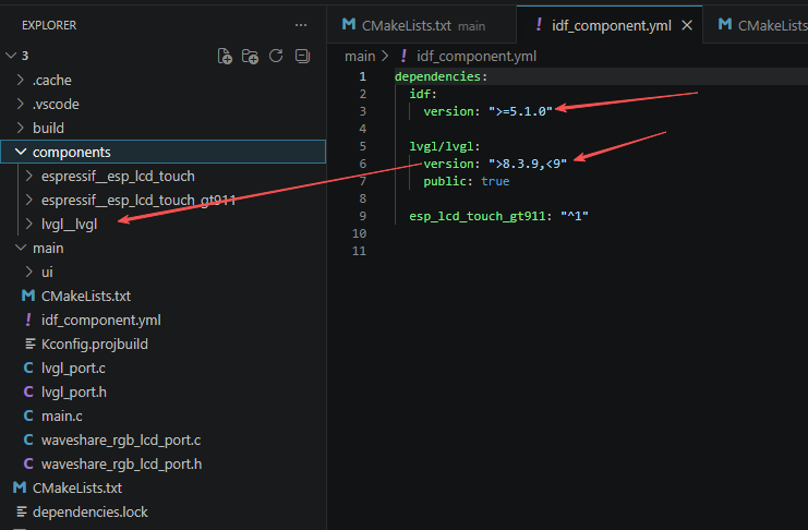
First, configure the required framework versions in the idf_component.yml file located in the main folder. This project is developed using ESP-IDF 5.5.4 and LVGL 8.3.11, so make sure the version settings in the file match these requirements or fall within the specified compatibility range. Doing so ensures that all dependencies are installed correctly and helps prevent compilation or compatibility errors.
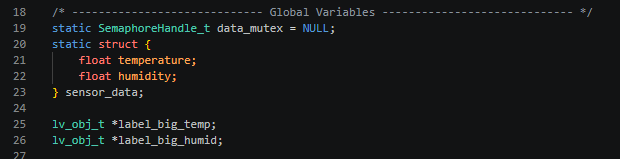
This section declares the global shared resources of the project. "data_mutex" is the handle of the FreeRTOS mutex lock, which is used to isolate the concurrent reading and writing of the temperature and humidity structure by the sensor reading task and the interface refresh task, preventing data corruption; the "sensor_data" structure is used to cache the latest collected floating-point temperature and humidity data, serving as a data exchange buffer for the two tasks; two lv_obj_t pointers point to the large text control widgets on the LVGL interface, and these handles are globally saved to facilitate the refresh task to modify the text content at any time.
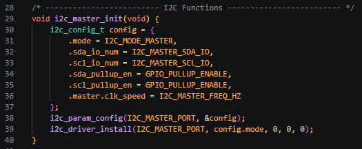
This section completes the initialization of the hardware I2C1 channel host, fills the configuration structure to set it to host mode, binds the preset SDA/SCL pins, enables the internal pull-up resistor to ensure stable high-speed I2C levels, configures a 400KHz communication clock; calls the underlying API to write the configuration to the hardware channel and install the I2C driver, closes the receive and transmit buffers to reduce memory usage, and provides a unified I2C communication bus for the DHT20 sensor, the 0x30 touch chip, and the TCA9534 expansion IO chip.
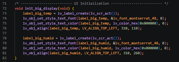
In this section, two large-sized text controls are created independently on the current screen of LVGL, respectively used to display the temperature and humidity values; a 48-point bold font and pure black text are uniformly set, with a fixed coordinate layout. The temperature text is located at the horizontal coordinate 310 and the vertical coordinate 110, while the humidity text is located at the horizontal coordinate 310 and the vertical coordinate 260. After the function runs, the two control pointers are saved to global variables, and subsequent refresh tasks can directly modify the control text to update the temperature and humidity values.
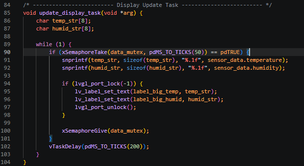
This section is an independent loop task of FreeRTOS, responsible for reading the cache temperature and humidity and refreshing the screen UI. A character array is defined to store the formatted temperature and humidity strings; it loops every 200 milliseconds. First, it attempts to acquire the mutual exclusion lock to protect the shared data. After obtaining the lock, it converts the floating-point temperature and humidity with one decimal place to text; the LVGL interface is not thread-safe. After locking the graphic resources through lvgl_port_lock, it updates two large text controls. After the update is completed, it releases the graphic lock and the data mutual exclusion lock in sequence. If there is no data, it waits for 50ms to time out and give up this refresh to avoid blocking the task scheduling.
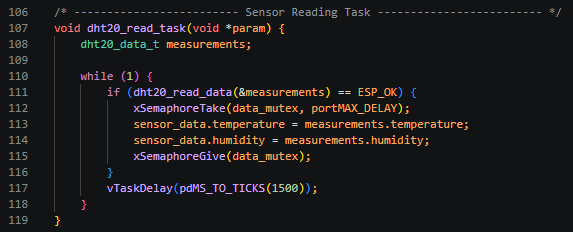
This section is an independent sensor data collection task. The DHT20 temperature and humidity data is read once every 1.5 seconds. After successful reading, it will permanently block and wait for the mutual exclusion lock. After obtaining the lock, the latest temperature and humidity will be stored in the global shared structure. Once the writing is completed, the mutual exclusion lock will be released immediately to ensure that the interface refresh task does not encounter half-write disorder when reading the data. If the reading fails, it will directly skip this data update and wait for the next collection cycle.
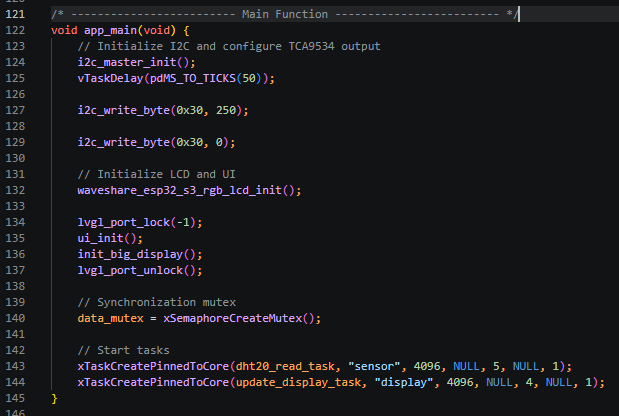
This section is the sole entry point for the ESP-IDF program. Upon power-on, it sequentially completes the initialization of the entire hardware, interface, and multitasking: first, it initializes the I2C1 bus and waits for the peripherals to power up and stabilize; it sends instructions to the 0x30 chip to turn on the touch screen and illuminate the screen backlight; it calls the microsnow RGB screen hardware initialization function, locks the LVGL resource loading of the basic UI interface and creates a large temperature and humidity text control; after completion, it releases the graphics lock; it creates a mutex lock for data synchronization between the two tasks; finally, it creates two independent tasks bound to the CPU1 core. The priority of the sensor acquisition task is 5, which is higher than the priority of the interface refresh task, 4. This ensures that the temperature and humidity acquisition is not blocked by the interface refresh. The task stack size is evenly allocated at 4096 bytes to prevent memory overflow. After initialization, the system automatically schedules the two tasks to cycle for screen acquisition and refresh.
5. Compile and flash the code
Select the code folder for this lesson, right-click on it, and then choose to open it with VS Code.
Note:
Remember to prepare the hardware environment as per the first point of this course.
Then, following Step 5 “Run the program” from Lesson 1, upload and execute the code in the correct sequence.
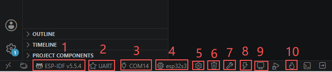
Please proceed in the following order: 1 → 2 → 3 → 4 → 5 → 6 → 10
You can observe the current temperature and humidity on the screen.
Kind Reminder:
You are currently viewing the 7-inch product of CrowPanel Advance HMI AI Display, and the version here is V1.3 / V1.4 / V1.5.
(For the 4.3-inch V1.1 / V1.2 / v1.3 version and the 5.0-inch V1.2 / v1.3 version, the following information also applies.)
In terms of hardware, we use a microcontroller (STC8H1K28) to control the screen backlight, speaker on/off, and buzzer.
(However, there are other function interfaces that need to be written in the specific code, and you can refer to the complete code provided later.)
Explanation:
-
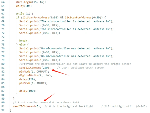
0x30 is the I2C address of the microcontroller (STC8H1K28).
-
0x5D is the I2C address of the touch IC (GT911).
-
sendI2CCommand(0) means sending command 0 to the microcontroller (address 0x30) to instruct it to set the screen brightness to maximum.
For 0 mentioned above, you can replace it with the following values:
- 0 is the brightest backlight.
- 0 to 245: The screen brightness will gradually increase to the minimum value
- 245 represents turning off the screen light
Additional notes:
You can also control the following functions by sending other instructions to the microcontroller:
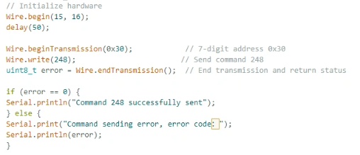
- It means sending the 248 command to the microcontroller (0x30) to instruct the speaker to turn on.
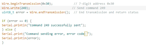
- It means sending the 249 command to the microcontroller (0x30) to instruct the speaker to turn off.
- You can also send command 246 to control the buzzer to turn on, and send command 247 to control the buzzer to turn off.
