Lesson3 Use SquareLine Studio and LVGL libraries to create a UI interface to light the lights
Welcome to the third lesson of learning. I believe that after completing the last two lessons, everyone has gained a deeper understanding of our product. Next, I will lead you to the second application case of the Advance series products - Display the interface by calling LVGL technology and control the on - off state of the small light bulb.
1. Using previous preparations
For the 4.3-inch, 5.0-inch, and 7.0-inch development boards, connect the small light bulb to the UART1-OUT port.
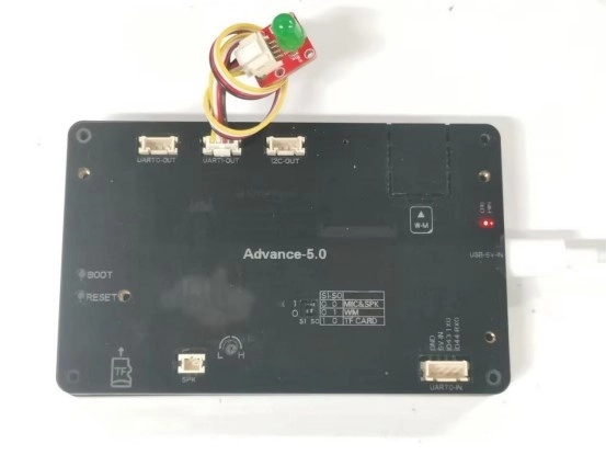
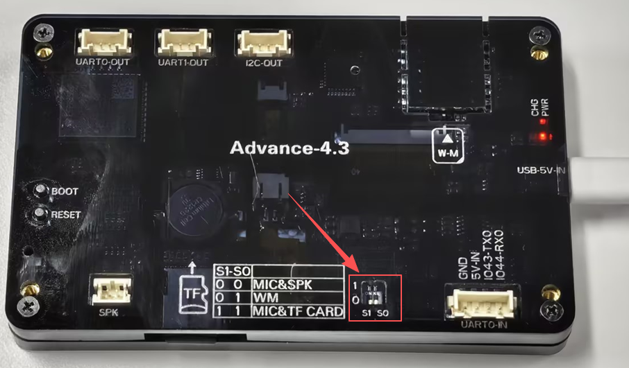
For the development versions with screen sizes of 4.3-inch, 5.0-inch, and 7.0-inch, the function select keys should be set to 0 1.
2. Introduce LVGL
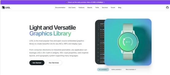
LVGL (LittlevGL) is an open-source, lightweight, high-performance embedded graphics library designed specifically for devices with limited resources. It supports multi platform porting, provides rich controls, animations, touch support, and highly customizable styles, suitable for fields such as smart homes, industrial equipment, medical instruments, etc. LVGL is centered around modular design and can run on bare metal or operating systems, accelerating GUI development through powerful community support and tools such as SquareLine Studio.
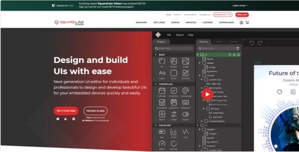
SquareLine Studio is a next-generation user interface (UI) solution for individuals and professionals, allowing users to quickly and easily design and develop aesthetically pleasing UI for embedded devices. This software provides integrated design, prototyping, and development capabilities, supporting the export of platform independent C or MicroPython code for LVGL (Lightweight Graphics Library), which can be compiled and run on any vendor's device.
3. Install SquareLine Studio
3.1 Installation Guide
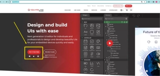
Enter the https://squareline.io/ to download the SquareLine installation file.
Download the version 1.4.0
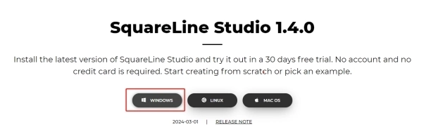
Double-click the setup.exe file.
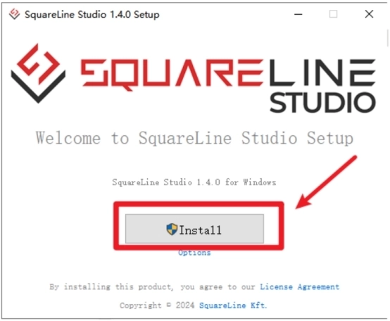
Click install.
Wait for installation.
Installation finish.
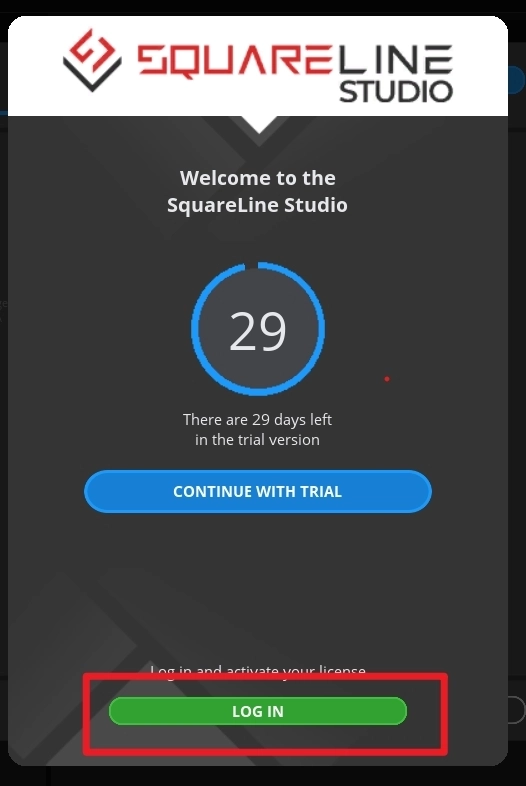
There is a 30-day trial period for the first time you use it. Please follow the prompts to register an account. You will continue to use it when you log in to your account next time.
3.2 Software Function Introduction
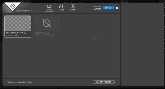
Open the software
The historical project page: open the project built earlier.
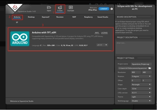
Create a project page: choose different platforms according to different hardware of the project.
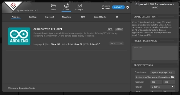
When select the Arduino framwork, there's only one option "Arduino with TFT_eSPI". By choosing this, the squareline studio will generate a template code suitable for the TFT_eSPI library. However, squareline studio not only supports the TFT_eSPI library, it supports a variety of libraries to suit different hardware and application needs. For example, Adafruit_GFX library, LovyanGFX etc.
After using SLS to generate UI code, we then use different graphics libraries according to different hardware and modify the corresponding code to display the content you design.
Example page. This page has several official examples for reference.

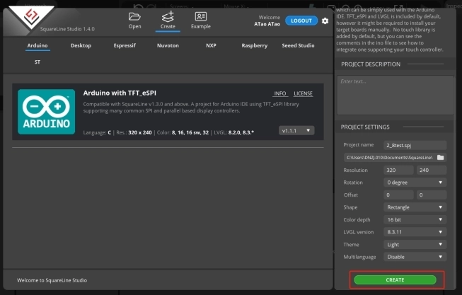
The project settings bar is used to make basic settings for the project, including property settings such as project name, screen size, display angle, etc.
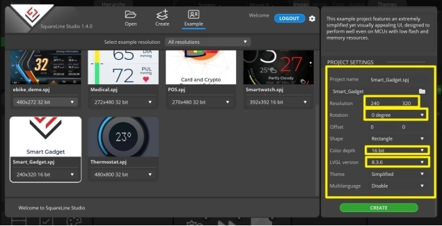
Note:Please select the corresponding resolution and color depth according to the screen specifications.

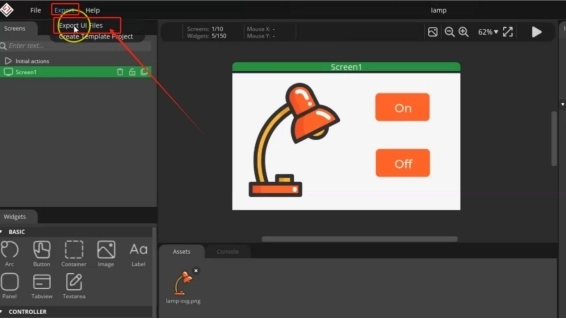
①Toolbar, including File, Export, and Help. Basic file operation bar, create or open files, export UI files and other operations. Click help and there are related introductory documents.
②Screen bar, the project screen will be listed here.
③Widget area, all widgets are here and can be selected and used according to project needs.
④Hierarchy area, it will show every widget used in each screen.
⑤This area shows the actual display effect, you can adjust the widgets or screen here.
⑥Material column, the added materials are displayed here.
⑦Setting bar, where you can make basic settings for each part, including the basic attributes and trigger operations of the part.
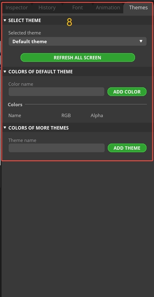
⑧Theme bar, different themes can be set.
4. Use SquareLine Studio to create UI control interfaces
4.1 Create a new SquareLine Studio project.
Firstly, open the SquareLine Studio software and create a case study
Choose the correct resolution based on the different sizes you are using
Here, I take a 2.8-inch screen as an example. After determining the resolution, I fill it in.
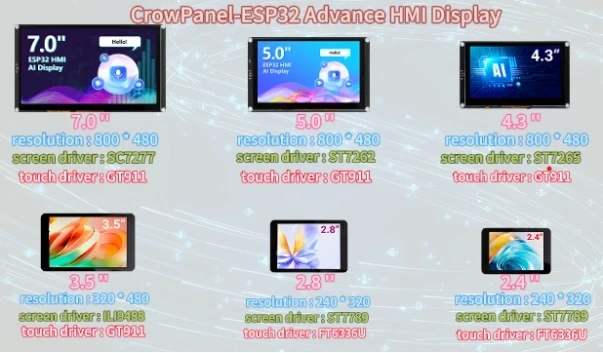
If you are using the 4.3-inch, 5.0-inch, or 7.0-inch version of the product, you will need to set the display resolution to 800 × 480, according to the size comparison chart shown above.
Please note that this project uses the LVGL 8.3.11 version. Make sure to configure the correct LVGL version to ensure compatibility with the provided code and examples.
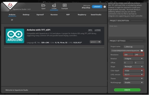
After selecting the parameters, click Create
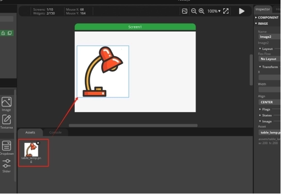
Open the photo of the desk lamp we provided and add it in. (Of course, you can also choose the image you want to use)
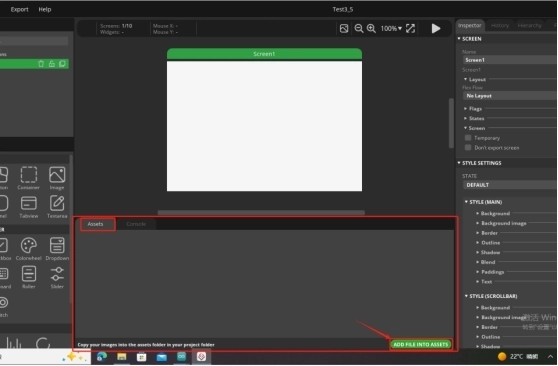
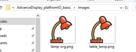
The images can be found at the following location:
Just use the pictures here.
The lamp-svg image size is available for both 2.4-inch and 2.8-inch screens.
The table_lamp image sizes are available for 3.5-inch, 4.3-inch, 5.0-inch, and 7-inch screens.
After adding it, drag and drop the image in.
The task we need to complete is to turn on and off the lights by clicking on the buttons on the graphical interface. So we need to design two buttons
From the left sidebar, select Button and drag it into the interface.
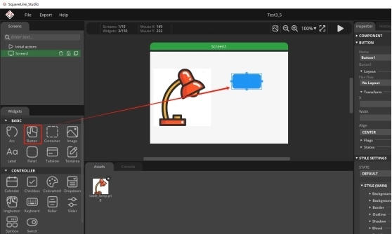
You can adjust the border of the button with the mouse, which can adjust the size of the button, and you can also drag and drop the button to adjust its position.
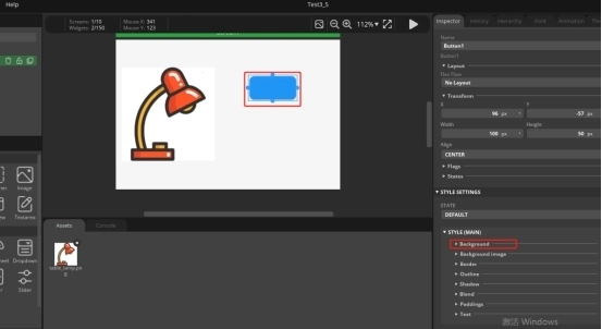
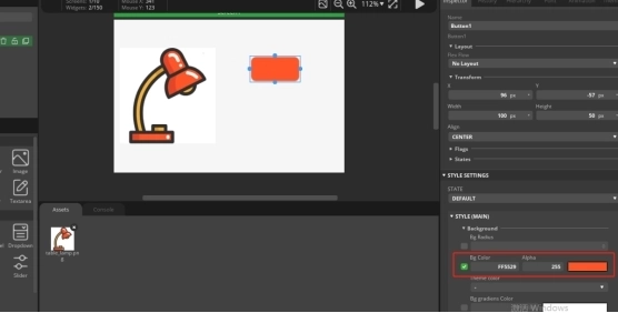
Then, by selecting Background, choose the background color of the Button.
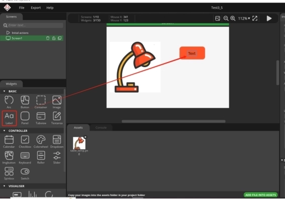
We have made the button patterns, and now we need to add labels to the button patterns in order to distinguish their functions.
Drag and drop from the left sidebar, select Label, and drag into the interface.
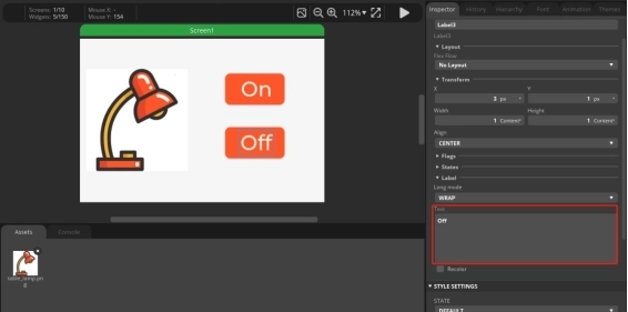
Modify the text content of the label
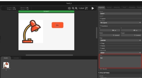
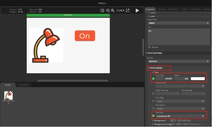
And modify the font size and text color of the text
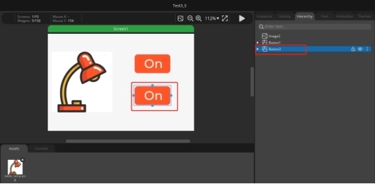
The Button and Label have been designed. Click on the Hierarchy in the right-hand column and drag the Label onto the Button line to merge them into one.
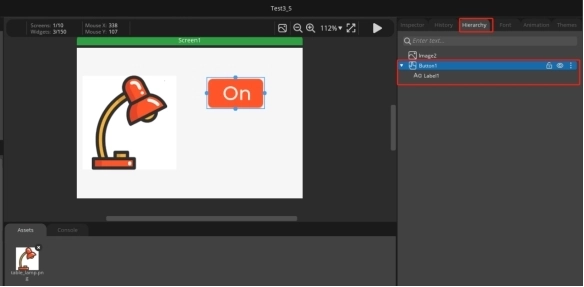
At this point, if you drag the buttons again, you will find that they are dragged together
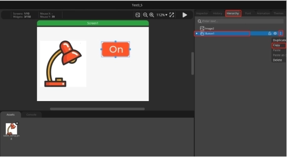
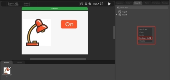
Next, we will copy a completed button, right-click, and paste it in.
Click the second button ON to change the text content to Off. Used to achieve the effect of turning off lights.
4.2 Add functions to the buttons to enable them to turn on and off lights
Select 'event' to add in the right sidebar.
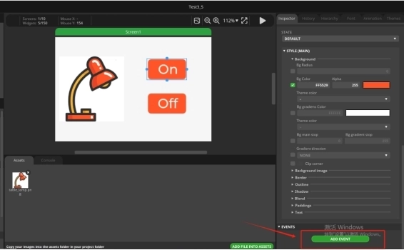
Select 'released' as the triggering condition and 'Call function' as the action.
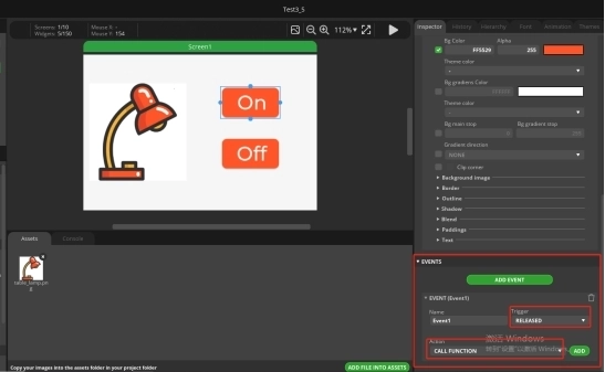
After selecting, click ADD.
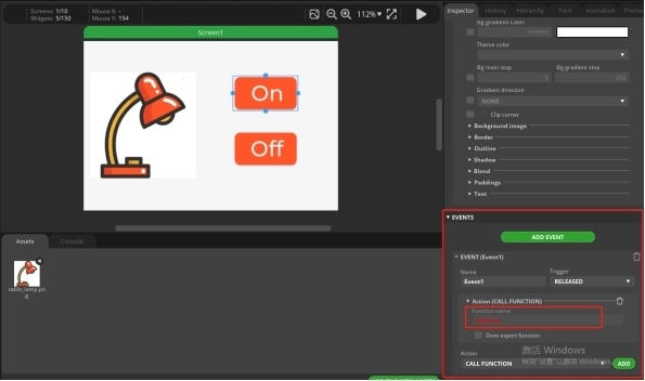
And add a function name to the CALL Function. (Customization is sufficient)
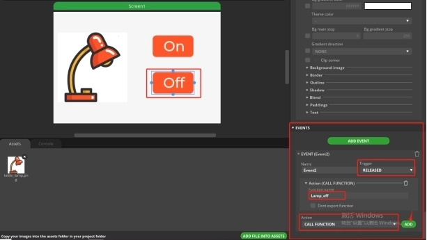
Similarly, add an event to the Off button. The operation process is the same as above.
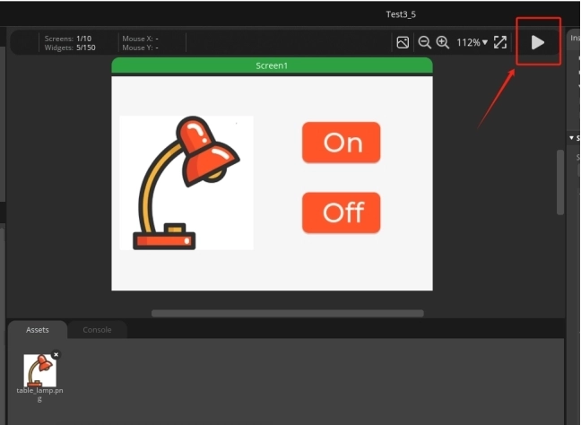
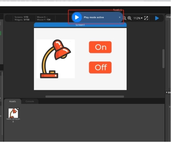
After adding, run
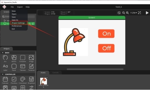
4.3 UI interface design completed, exporting UI files for easy use in subsequent code
Click on Project Setting
Set export path.
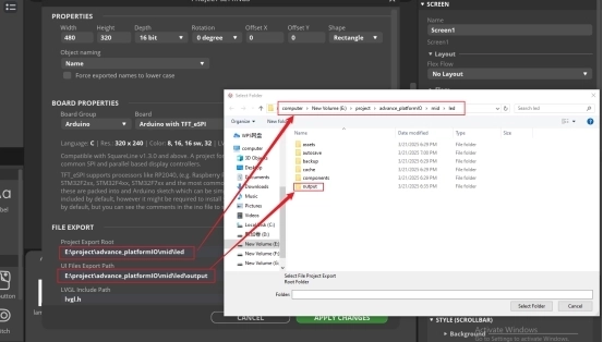
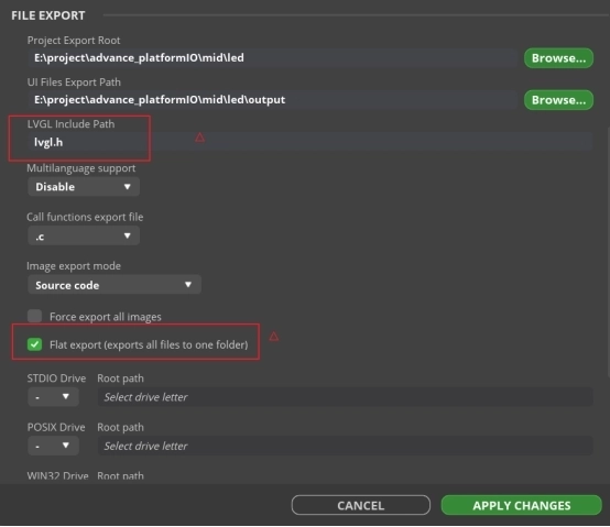
Complete the setup and export file.
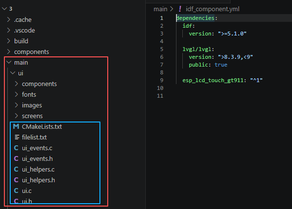
Next, open the project folder provided for this course using VS Code. Then, copy the .h and .c files generated by LVGL into the corresponding ui folder of the project. You can download the complete project code from the link provided below.
5. Explanation of the code project
This project is developed and run on ESP-IDF version 5.5.4.
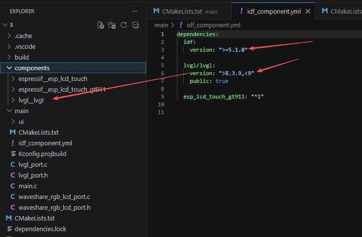
First, configure the required framework versions in the idf_component.yml file located in the main folder. This project is developed using ESP-IDF 5.5.4 and LVGL 8.3.11, so make sure the version settings in the file match these requirements or fall within the specified compatibility range. Doing so ensures that all dependencies are installed correctly and helps prevent compilation or compatibility errors.
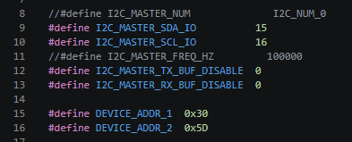
This section uses macros to uniformly manage the hardware parameters and peripheral addresses of the I2C bus. The comments have masked the I2C channel number and bus frequency. These can be enabled by removing the comments later. Specifically, the I2C data line SDA pin 15 and the clock line SCL pin 16 have been clearly specified. The built-in I2C transceiver buffers have been disabled to reduce memory usage. Two fixed I2C slave device addresses 0x30 (touch / power amplifier control chip) and 0x5D (screen driver chip) have been defined. Through the use of macros to uniformly manage the hardware parameters, changing the wiring and changing the chip address only requires modifying this section, without the need to traverse the entire code.
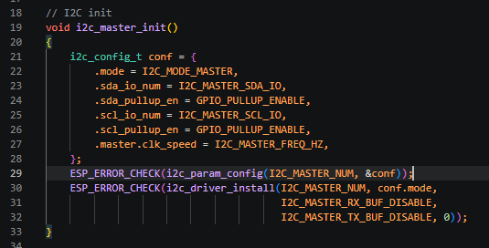
This section completes the complete initialization of the ESP32 hardware I2C host. Firstly, the I2C configuration structure is defined, the working mode is set as the host, the preset SDA/SCL pins are bound, the internal pull-up resistors of the pins are enabled to ensure the stability of I2C levels, and the bus clock frequency is filled in. The i2c_param_config function is called to write the configuration to the specified I2C hardware channel, and then the i2c_driver_install function is called to install the I2C driver and close the receive and transmit buffers. The ESP_ERROR_CHECK function will catch initialization errors. In case of hardware exceptions, the program will directly trigger an error and restart to ensure that the I2C bus can communicate normally with the 0x30 and 0x5D peripherals.
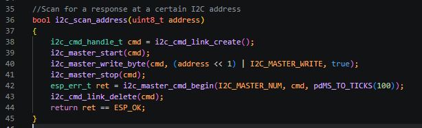
This section encapsulates the native ESP-IDF I2C scanning logic, receives the address of the device to be detected, first creates an I2C instruction list, and successively adds the start signal, the device address with read/write bits, and the stop signal; execute the entire I2C instruction and set a 100-millisecond timeout; upon completion of the execution, release the instruction list; the function returns a boolean value. If the I2C receives an external device response and there is no error during execution, it returns true, indicating that the corresponding address chip exists. This is used for power-on self-check to determine whether the touch and screen chips are properly mounted.
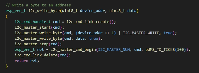
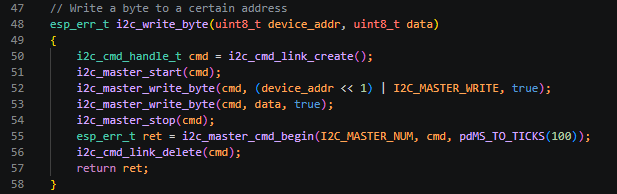
This section encapsulates a general interface for sending a single-byte control command to the specified I2C peripheral. The input parameters are the target device address and the control data to be sent. An I2C command queue is created, and the start signal, device write address, single-byte control command, and stop signal are sent sequentially. A 100ms communication timeout is added to prevent the bus from getting stuck. After the communication is completed, the command memory is released, and the communication error code is returned for the upper layer to judge whether the command transmission was successful. The screen backlight switch, touch enable, and power amplifier switch are all issued I2C commands through this function.
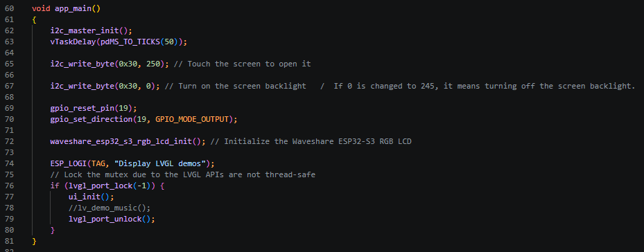
This section is the sole entry point for the ESP-IDF standard program. After power-on, it completes the initialization of the entire hardware and the graphical interface in a fixed sequence: Firstly, it initializes the hardware I2C master and waits for 50ms for the peripherals to power up and stabilize; it then issues the 0xFA (250) command to the 0x30 chip to enable the touch function, and then issues 0 to turn on the screen backlight; changing the value to 245 will turn off the backlight; it resets the GPIO19 pin and configures it as an output mode for screen power / backlight auxiliary control; it calls the dedicated RGB screen initialization function of Microchip to complete the screen hardware driver, memory, and refresh timing configuration; it prints log messages via serial port to prompt the entry into the LVGL graphical interface process. The LVGL functions are not thread-safe, so it locks the graphic resources with a mutex lock, calls ui_init to load the custom UI interface generated in advance using the LVGL editor, and comments out the official music demo. After initialization is complete, the mutex lock is released, and the entire process is completed, allowing the custom GUI interface to be displayed on the screen.
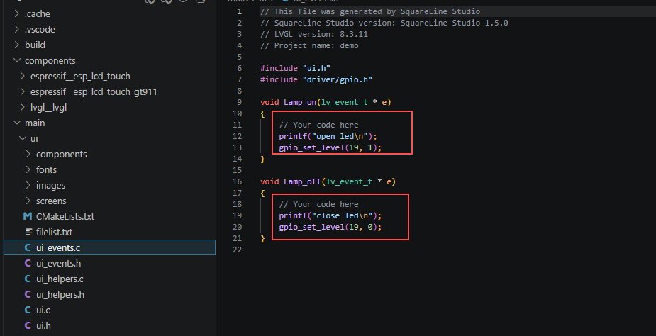
Finally, if you want to control the LED connected to the UART1-OUT interface by tapping the On and Off buttons on the screen, you need to implement the callback functions defined in SquareLine Studio inside the ui_events.c file located in the ui folder under the main directory.
6. Compile and flash the code
Click the link below and you can access the code for this lesson.
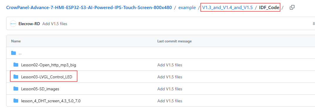
Select the code folder for this lesson, right-click on it, and then choose to open it with VS Code.
Note:
Remember to prepare the hardware environment as per the first point of this course.
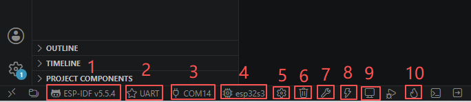
Then, following Step 5 “Run the program” from Lesson 1, upload and execute the code in the correct sequence.
Please proceed in the following order: 1 → 2 → 3 → 4 → 5 → 6 → 10
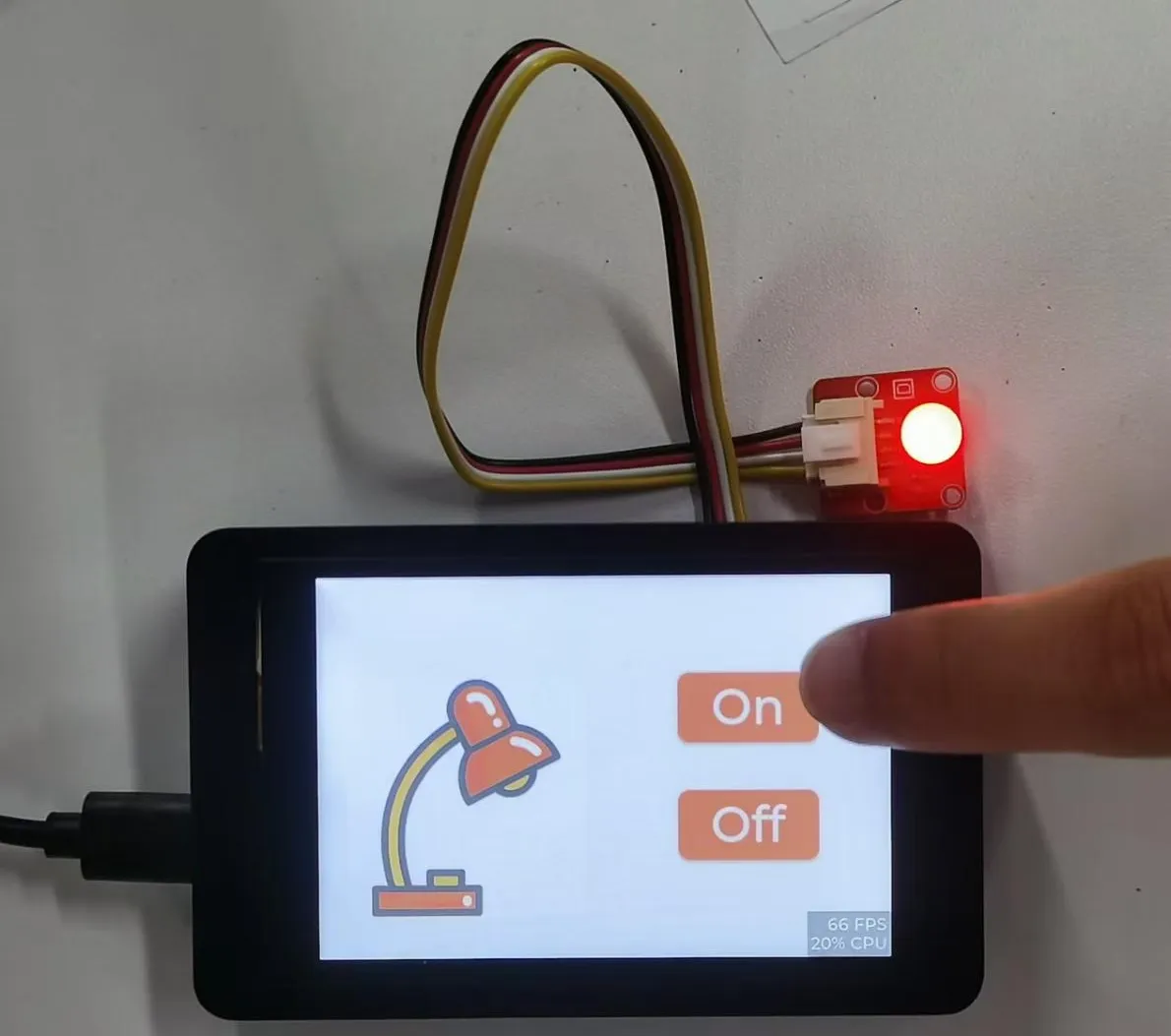
After completing Step 10, you will be able to see your LVGL interface displayed on the screen. In addition, tapping On will turn on the LED, while tapping Off will turn it off.

Kind Reminder:
You are currently viewing the 7-inch product of CrowPanel Advance HMI AI Display, and the version here is V1.3 / V1.4 / V1.5.
(For the 4.3-inch V1.1 / V1.2 / v1.3 version and the 5.0-inch V1.2 / v1.3 version, the following information also applies.)
In terms of hardware, we use a microcontroller (STC8H1K28) to control the screen backlight, speaker on/off, and buzzer.
(However, there are other function interfaces that need to be written in the specific code, and you can refer to the complete code provided later.)
Explanation:
-
0x30 is the I2C address of the microcontroller (STC8H1K28).
-
0x5D is the I2C address of the touch IC (GT911).
-
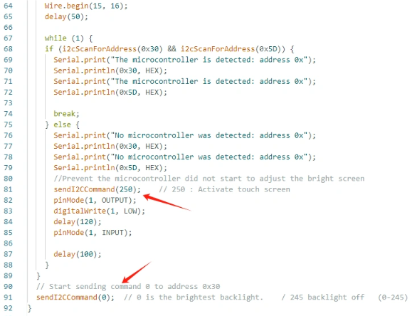
sendI2CCommand(0) means sending command 0 to the microcontroller (address 0x30) to instruct it to set the screen brightness to maximum.
For 0 mentioned above, you can replace it with the following values:
- 0 is the brightest backlight.
- 0 to 245: The screen brightness will gradually increase to the minimum value
- 245 represents turning off the screen light
Additional notes:
You can also control the following functions by sending other instructions to the microcontroller:
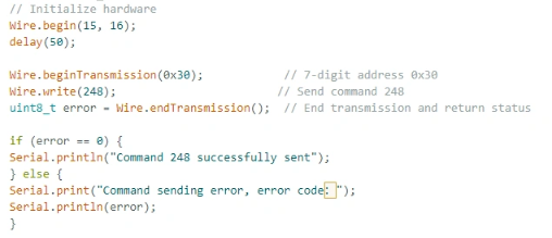
- It means sending the 248 command to the microcontroller (0x30) to instruct the speaker to turn on.
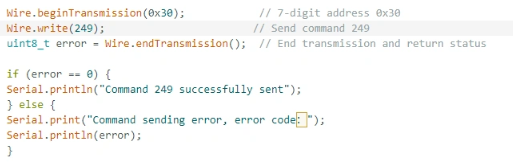
- It means sending the 249 command to the microcontroller (0x30) to instruct the speaker to turn off.
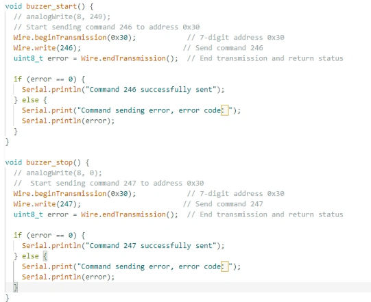
- You can also send command 246 to control the buzzer to turn on, and send command 247 to control the buzzer to turn off.
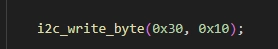
By writing the instruction 0x10 to the address 0x30 of the microcontroller, it is used to control the microcontroller.