Lesson2 Introduce the screen user interface and external speakers for playing songs
Welcome to the second lesson of learning. I believe that after completing the first lesson, everyone has gained a deeper understanding of our product. Next, I will lead you to the first application case of the Advance series products - connecting to WiFi to play songs.
1 Using previous preparations
Note:Plug a speaker into the "SPK" interface,Connect the development board to the computer with a Type-C cable.
For the development versions with screen sizes of 4.3-inch, 5.0-inch, and 7.0-inch, the function select keys should be set to 0 0.
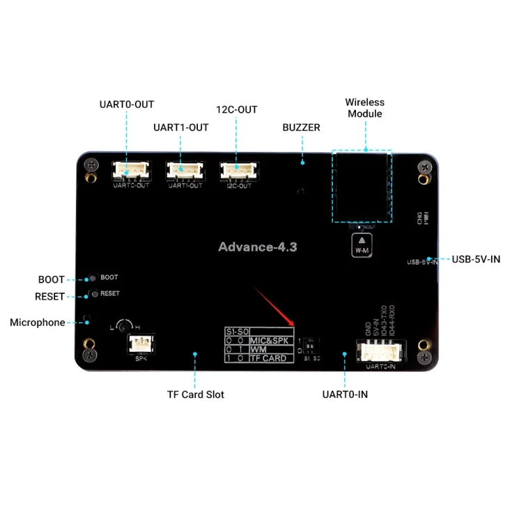
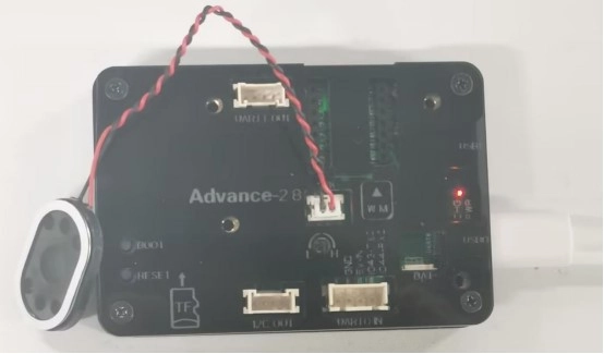
Then connect the speaker to the CrowPanel-Advance-HMI-AI-Display.
2 Explanation of the code project
This project is developed and run on ESP-IDF version 5.5.4.
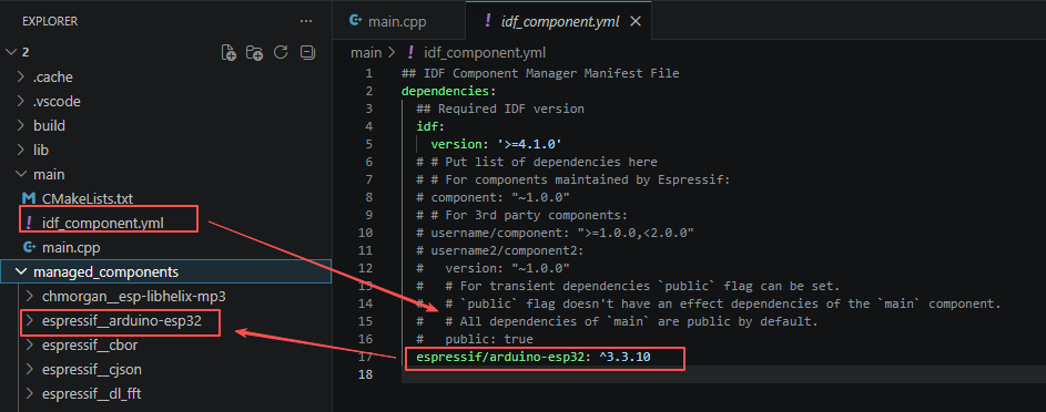
First, you need to specify the version of the arduino-esp32 component in the idf_component.yml file under the main folder. In this project, version 3.3.10 is used to ensure compatibility with ESP-IDF 5.5.4. After the configuration is completed, the ESP-IDF build system will automatically download and integrate the specified Arduino framework version during the first compilation.
This setup allows the project to combine the ESP-IDF development environment with the Arduino programming interface, enabling the use of Arduino-style APIs within an ESP-IDF-based project.
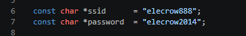
This section defines two string constants to store the WiFi name and connection password of the target router. The use of "const" modifier ensures that the account password will not be accidentally modified during the running process. The global scope enables all functions in the entire project to directly read this WiFi parameter. The subsequent WiFi connection function will read these two variables to complete the wireless network configuration.
This section defines the global string constant to store the public MP3 external link address of NetEase Cloud Music. The audio library will access this address via the TCP network to retrieve the online audio data stream. Subsequent playback functions will directly call this address to achieve online song playback. The audio resources come from the online HTTP streaming media, and there is no need for local storage of audio files.
The song must be free and not a VIP song. And you just need to replace the song code "1391891631" with another one.

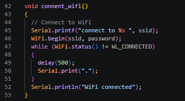
This section implements the blocking networking logic for ESP32 to connect to a specified WiFi hotspot. Firstly, it prints the WiFi name to be connected via the serial port, then calls WiFi.begin to start the wireless connection process. It enters an infinite loop to continuously monitor the WiFi connection status. If the connection is not successful, it prints a dot marker every 500 milliseconds to indicate the progress. Only when the wireless connection status becomes "connected" will the loop be exited and the connection success log will be printed. The program will remain stuck in this function until the network connection is completed and will not execute the subsequent audio and screen initialization code.
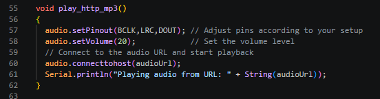
This section completes the audio hardware configuration and the online streaming media startup process. First, it binds the pre-defined three I2S audio pins to the global audio object, sets the global playback volume value to 20, calls the network connection interface to access the pre-stored MP3 link of NetEase Cloud, automatically completes the network request, audio buffering, MP3 decoding, and I2S output entire process. Finally, it prints the current playing audio address through the serial port, and after the execution is completed, the hardware can output the music sound.
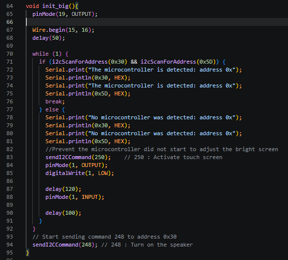
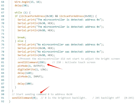
This section is responsible for the complete power-on self-check and initialization of the screen, touch, and power amplifier I2C peripherals. First, GPIO19 is configured as an output pin to be used as the screen backlight control. The I2C bus is initialized, specifying SDA pin 15 and SCL pin 16. Then, a permanent loop of dual-address device detection is entered. At the same time, the 0x30 power amplifier touch chip and the 0x5D screen chip are scanned. Both devices are recognized before the self-check loop is exited and a log of successful device detection is printed. If any peripheral does not respond, a log of device absence is printed, a touch activation command is issued, and GPIO1 is pulled low to perform a hardware reset, followed by a delay before releasing the reset pin. The loop is repeated until the peripheral is normal. After the self-check is completed, an I2C command to turn on the speaker and power amplifier is issued to complete the hardware initialization of all peripherals.
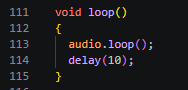
This section represents the main logic that runs in an infinite loop after the program is powered on. The core continuously calls the "loop" refresh function of the audio library. This function is responsible for maintaining the network audio buffer, continuously decoding MP3 data, and pushing the audio signal to the I2S hardware output. It is the key to ensuring that the music does not lag or stop. It is accompanied by a 10-millisecond delay to appropriately release CPU resources, avoiding the audio process monopolizing the chip's computing power. There are no other additional business logics. The entire process only maintains the audio playback state.
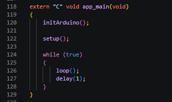
This section is the program startup entry adapted for the native development framework of ESP-IDF. The "extern "C"" ensures that the underlying C language kernel can properly call this function. Firstly, the initArduino function initializes the Arduino runtime environment, then directly calls the Arduino standard setup to complete all hardware network initialization. Subsequently, a permanent while loop is started to continuously execute the loop audio refresh logic. A 1-millisecond short delay is added to schedule other tasks for the system, allowing this Arduino syntax code to be compiled and run directly in the ESP-IDF project without relying on the Arduino IDE.
3 Compile and flash the code
Click the link below and you can access the code for this lesson.
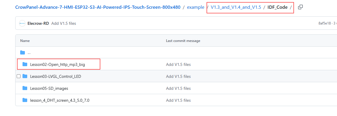
Select the code folder for this lesson, right-click on it, and then choose to open it with VS Code.
Note:
Remember to replace the Wi-Fi name and Wi-Fi password you are using at the beginning of the main.cpp file.
Then, following Step 5 “Run the program” from Lesson 1, upload and execute the code in the correct sequence.
Please proceed in the following order: 1 → 2 → 3 → 4 → 5 → 6 → 10
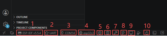
After completing Step 10, you will be able to hear the song playing through the speaker connected to the SPK output.
Kind Reminder:
You are currently viewing the 7-inch product of CrowPanel Advance HMI AI Display, and the version here is V1.3 / V1.4 / V1.5.
(For the 4.3-inch V1.1 / V1.2 / v1.3 version and the 5.0-inch V1.2 / v1.3 version, the following information also applies.)
In terms of hardware, we use a microcontroller (STC8H1K28) to control the screen backlight, speaker on/off, and buzzer.
(However, there are other function interfaces that need to be written in the specific code, and you can refer to the complete code provided later.)
Explanation:
-
0x30 is the I2C address of the microcontroller (STC8H1K28).
-
0x5D is the I2C address of the touch IC (GT911).
-
sendI2CCommand(0) means sending command 0 to the microcontroller (address 0x30) to instruct it to set the screen brightness to maximum.
For 0 mentioned above, you can replace it with the following values:
- 0 is the brightest backlight.
- 0 to 245: The screen brightness will gradually increase to the minimum value
- 245 represents turning off the screen light
Additional notes:
You can also control the following functions by sending other instructions to the microcontroller:
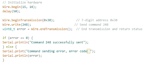
- It means sending the 248 command to the microcontroller (0x30) to instruct the speaker to turn on.
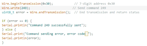
- It means sending the 249 command to the microcontroller (0x30) to instruct the speaker to turn off.
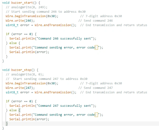
- You can also send command 246 to control the buzzer to turn on, and send command 247 to control the buzzer to turn off.