Lesson4 The temperature and humidity sensor receives data in real time
Welcome to the Lesson 4 of learning.
This lesson will use the IIC interface and of this series of products to collect data from temperature and humidity sensors. In this lesson, we will use the knowledge of LVGL graphics library from Lesson 3 to create an interactive interface.
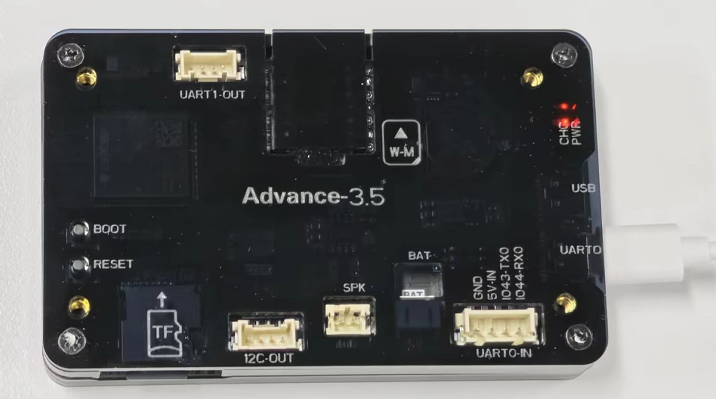
1. Introduce product ports
USB interface: used for power supply, serial communication, and automatic programming.
UART0-IN interface: supports power supply, serial communication, and entering manual burning mode by pressing BOOT+RESET; Other functions are consistent with the USB interface.
UART0-OUT interface: used for external power supply and serial communication.
UART1-OUT interface: uses soft serial port and supports configuring IO function.
I2C-OUT interface: connects RTC chip, extended IO chip (for screen backlight, touch screen reset, power amplifier pin control) and wireless module, only supports I2C communication.
This is the back view of the 3.5-inch V1.0 version.
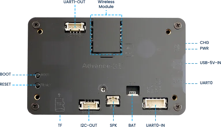
This is the back view of the 3.5-inch V1.2 / V1.3 / v1.4 version.
2. UI interface design
The temperature and humidity sensor needs to support IIC communication.
In order to provide everyone with an intuitive observation, I will use LVGL to create an interactive interface.
Open SquareLine Studio. If you haven't installed it, you can review the introduction of LVGL in Lesson 3.
Create "Espressif" project

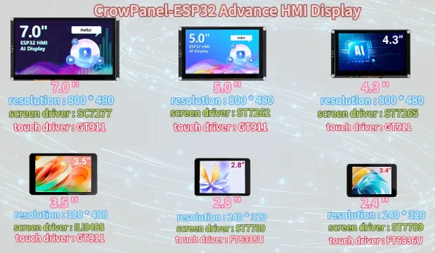
Note: For this lesson project, use LVGL v9.1.0 for 2.4-inch and 2.8-inch devices.
For 3.5-inch, 4.3-inch, 5.0-inch, and 7.0-inch devices, use LVGL v8.3.11.

Modify the file name and file storage path according to your needs (customization is sufficient)

Modify the appropriate resolution based on the different sizes you are using.
If you are using the 3.5-inch version of the product, you will need to set the display resolution to 480 × 320, according to the size comparison chart shown above.
Please note that this project uses the LVGL 8.3.11 version. Make sure to configure the correct LVGL version to ensure compatibility with the provided code and examples.
Finally, click on 'Create' to proceed.

Add the background image we provide based on the resolution required for the size you are using (choose different resolutions for different sizes, refer to the resolution size used for different sizes in Lesson 3)
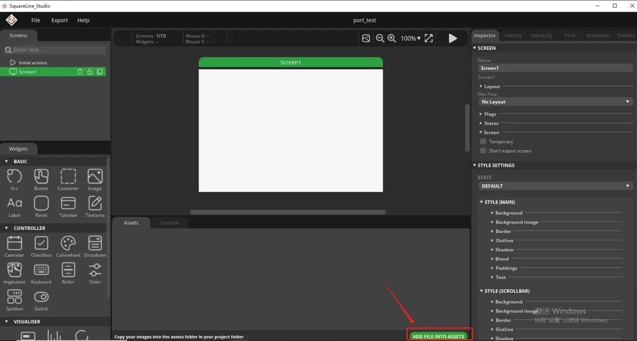
Here is the corresponding image asset download link for each screen size:

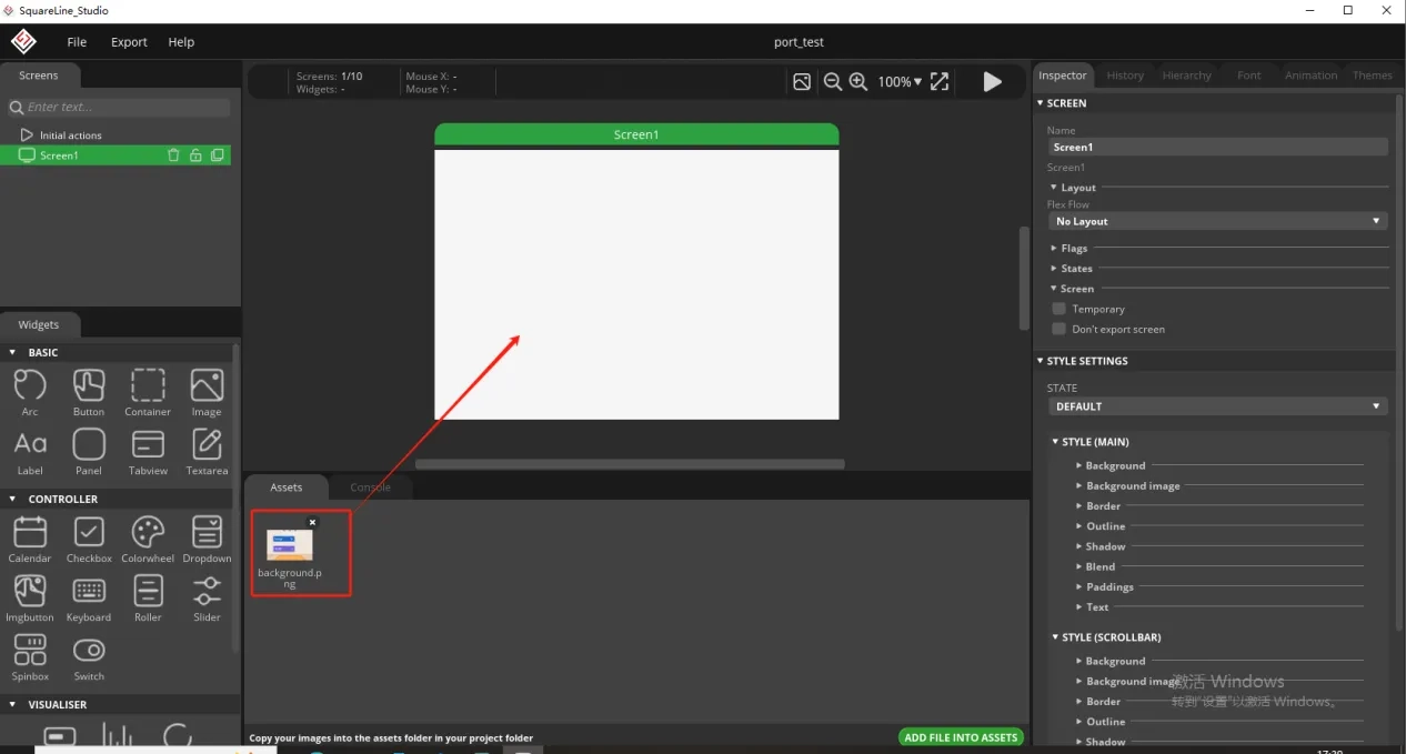
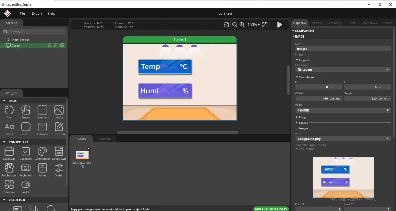
Add background image to the box.
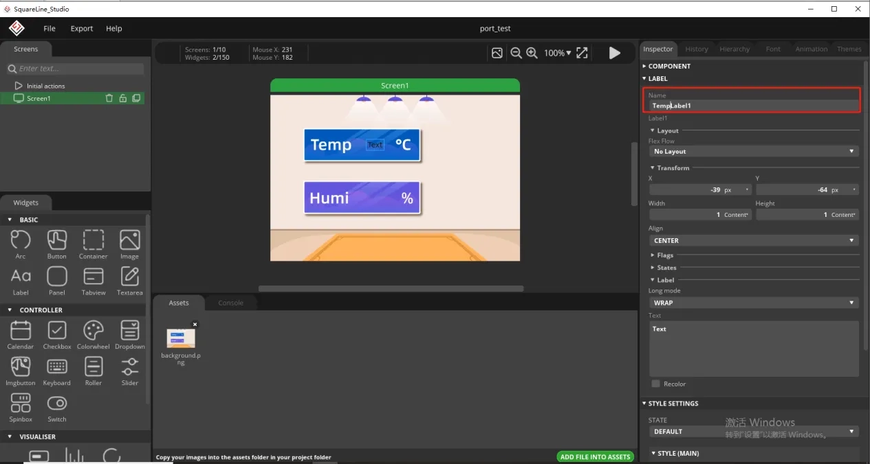
Since we need to display the temperature and humidity values on the screen, we need to add text in the two boxes for temperature and humidity.
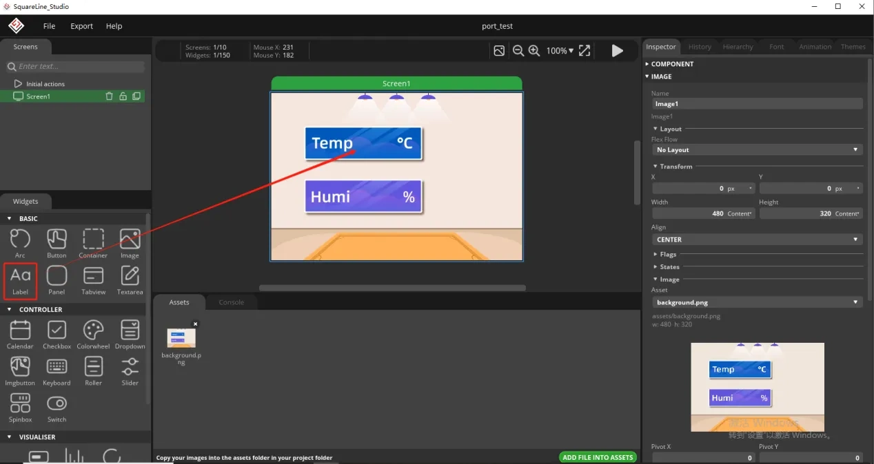
To distinguish between the other text labels that need to be created next, give this label a name to distinguish it.
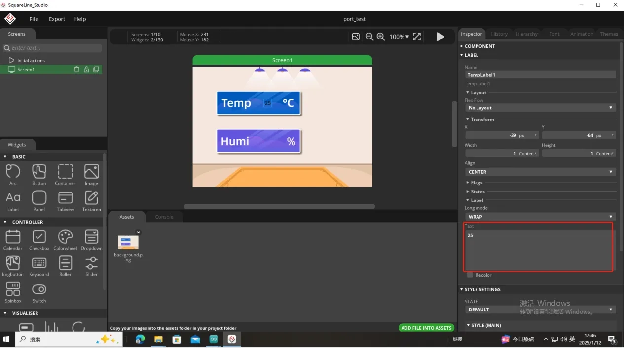
And fill in a default temperature value
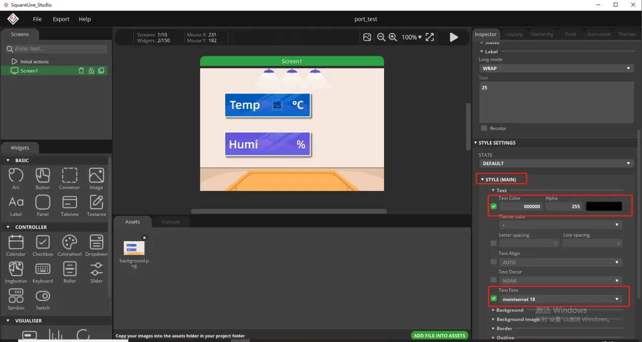
Of course, you can also set the font color and font size here
Copy the label just made and display the humidity value
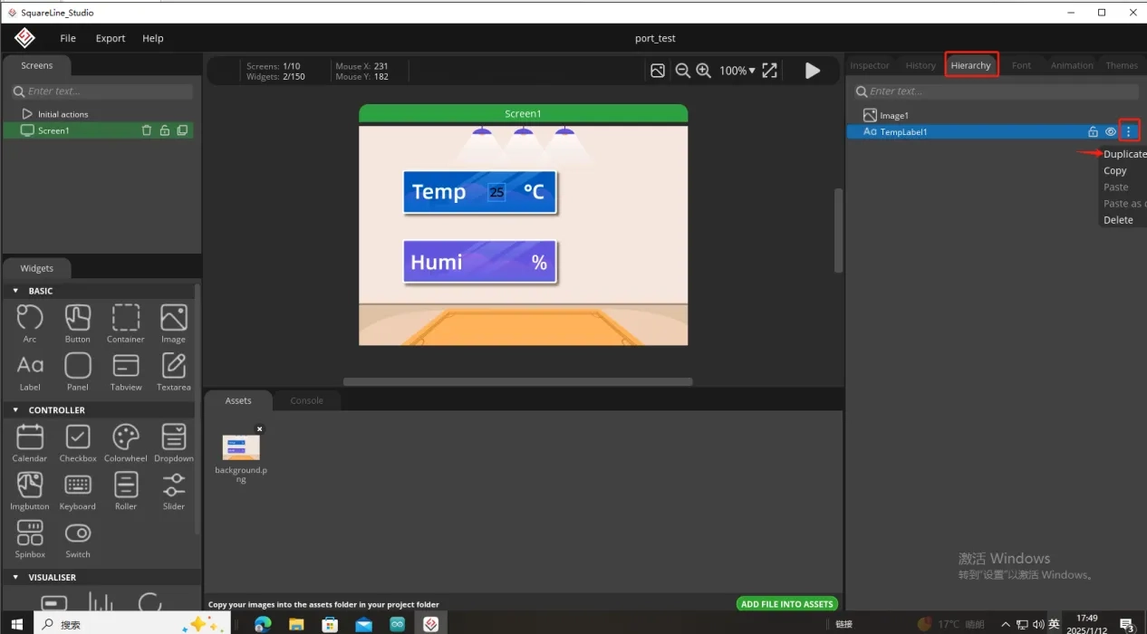
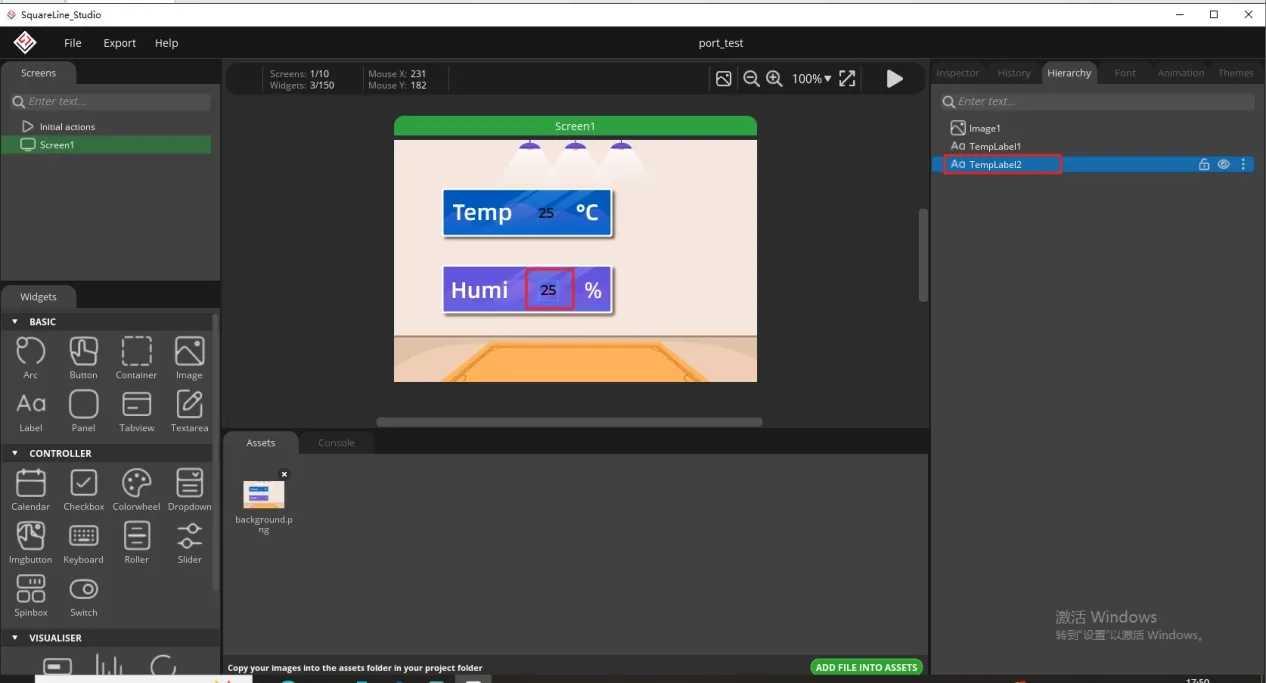
Follow the above steps to modify the humidity label
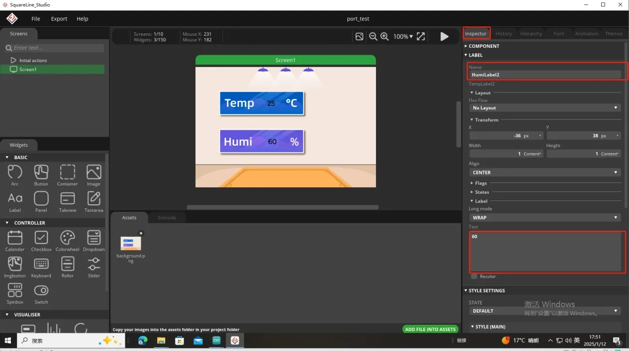
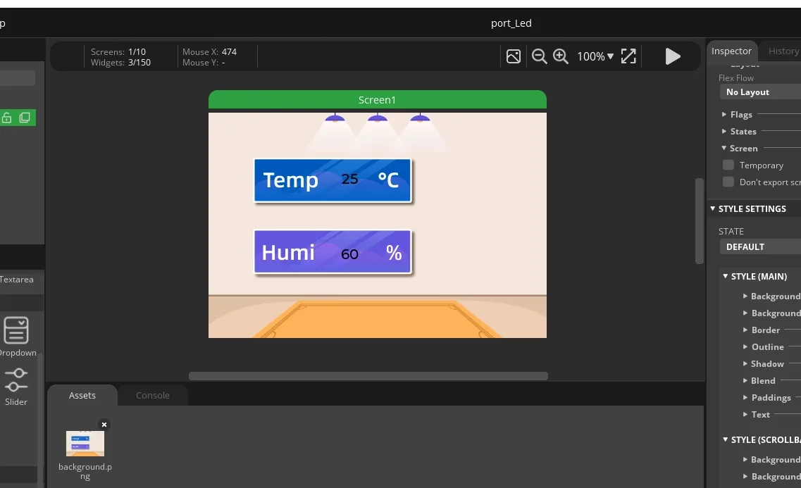
In this way, the display of temperature and humidity is completed.
So, the UI interface we need is completed.
Export the designed UI interface file
How to set the specific export path, please refer to the previous lesson.
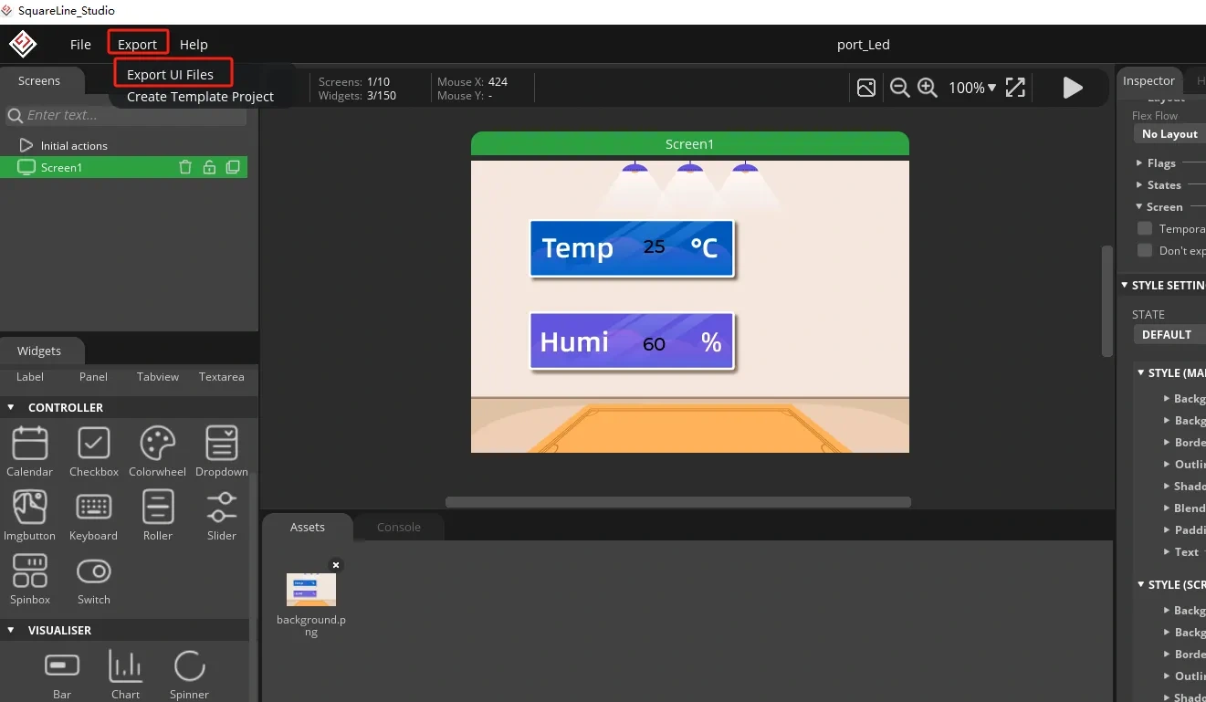
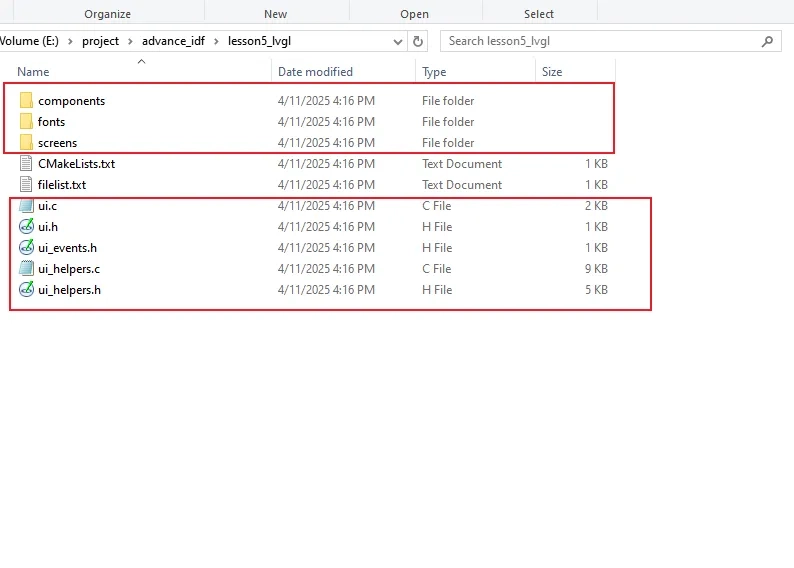
Go to the folder path where you selected to output the UI file.
Click the link below and you can access the code for this lesson.
Code Link:

Next, open the project folder provided for this course using VS Code. Then, copy the .h and .c files generated by LVGL into the corresponding ui folder of the project.

3. Hardware connection
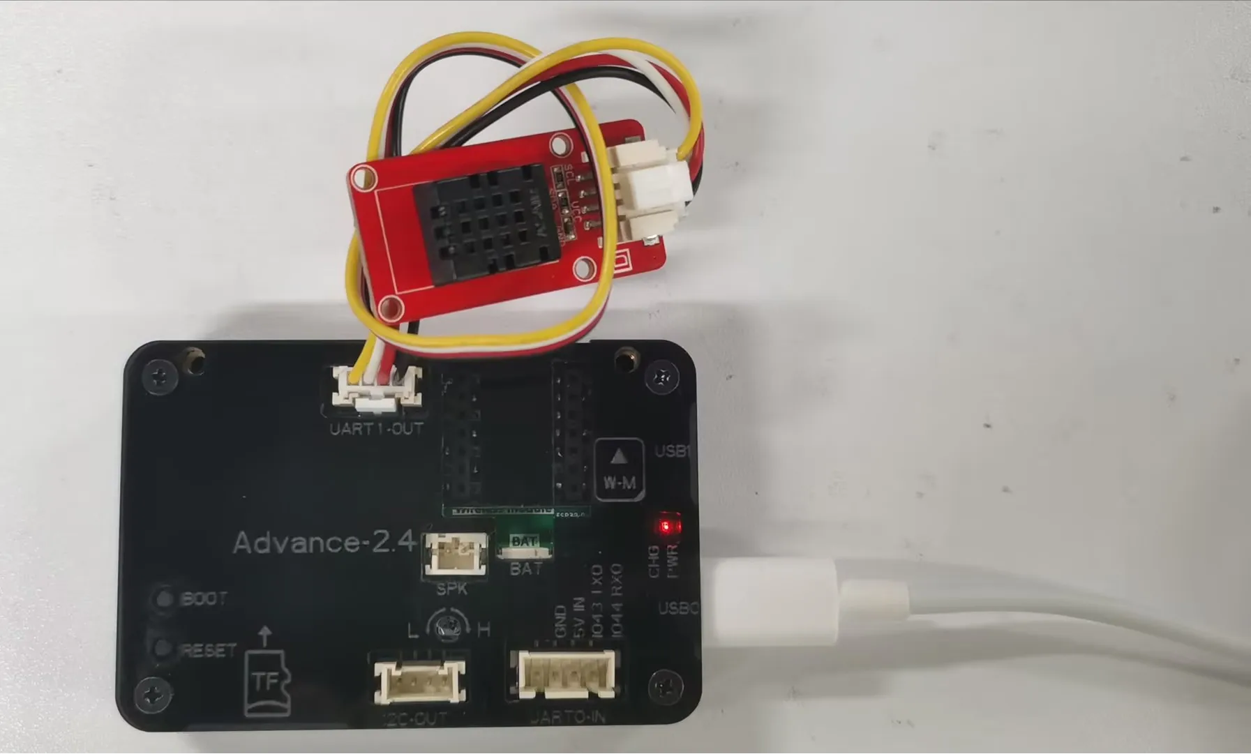
Connect the temperature sensor to the development board and power on the development board.
Note: For the 2.4-inch and 2.8-inch development boards, connect the temperature sensor to UART1-OUT. For other sizes, connect it to I2C-OUT.
Special Reminder:(The following applies only to 2.8-inch and 2.4-inch products)
The IIC address of the 2.8 and 2.4 touch driver ICs is 0x38, and the IIC address of the DHT20 temperature and humidity sensor is also 0x38. When the DHT20 temperature and humidity sensor is connected to the IIC-OUT interface for use, the two addresses conflict, causing abnormal device usage. The DHT20 temperature and humidity sensor will no longer work, but will ensure the driving of the touch IC.
So in order to make the DHT20 temperature and humidity sensor work, we can connect the DHT20 temperature and humidity sensor to UART1-OUT.
Special note: The UART1-OUT interface allows the use of two or fewer IO interfaces, namely 17 and 18 pins, for your convenience. For example, when connecting a light bulb, 18 pins can be used to receive the initiated control signal. For example, doing digital input/output and analog input/output. There are also some infrared receivers, buzzers, and lights that can be connected. The premise is that you should not use more than 2 IO ports, such as SPI, which requires four IO ports to control and cannot be used.
4. Explanation of the code project
This project is developed and run on ESP-IDF version 5.5.4.
First, you need to specify the version of the arduino-esp32 component in the idf_component.yml file under the main folder. In this project, version 3.3.10 is used to ensure compatibility with ESP-IDF 5.5.4. After the configuration is completed, the ESP-IDF build system will automatically download and integrate the specified Arduino framework version during the first compilation.
This setup allows the project to combine the ESP-IDF development environment with the Arduino programming interface, enabling the use of Arduino-style APIs within an ESP-IDF-based project.

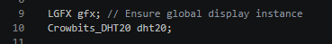
This section creates two global instances. The gfx of type LGFX is a global object for screen driver, ensuring that the refresh callback, touch reading, and screen configuration functions can access the screen hardware; dht20 is a DHT20 temperature and humidity sensor object. The global scope allows the setup initialization and loop update functions to directly read the temperature and humidity data, eliminating the need to repeatedly create instances and thus avoiding resource waste.
This section defines the screen resolution as 320 pixels wide and 480 pixels high. At the same time, it creates a double-row local refresh cache for LVGL. The "draw_buf" is the LVGL cache management structure, and "buf_1" and "buf_2" are two static memory blocks serving as drawing buffers. Each block of the cache has a width equal to the full screen width and a height of only 20 lines. It adopts the double-buffer local refresh mechanism to reduce the data transmission volume of the SPI screen and avoid screen tearing. The buffers are stored in the static memory area and do not occupy stack memory, thus preventing overflow.

This section encapsulates the logic for reading and refreshing the LVGL text control with temperature and humidity data, defines a 6-byte character buffer to store the numeric string; reads the integer temperature and humidity values from the DHT20 sensor, converts the numbers to strings using snprintf and assigns them to the temperature label ui_TempLabel1 on the interface; after clearing the buffer using memset, converts the humidity value to a string and assigns it to the humidity label ui_HumiLabel2. Each call will synchronously update the numeric display of temperature and humidity on the screen.

This section describes the standard one-time power-on initialization process for Arduino, which completes all hardware, sensor, and graphics system initialization in a fixed sequence:
- Open the 115200 baud rate serial port, wait for the serial monitor to open and print the boot log;
- Initialize the I2C bus with SDA=15, SCL=16, delay 50ms to wait for the I2C peripheral to power up and stabilize, then start the DHT20 temperature and humidity sensor;
- Configure GPIO38 as the backlight output pin. When powering on, first pull it low to turn off the backlight to avoid screen flickering during the initialization stage;
- Start the LovyanGFX screen hardware, set the screen rotation angle to 0 and the screen brightness to 128. After initialization is complete, pull up pin 38 to light up the backlight;
- Initialize the LVGL kernel, bind the double-line drawing buffer;
- Register the LVGL display driver, associate screen resolution, refresh callback and cache;
- Load the LVGL visual design interface ui_init, print the log of system initialization completion, and all hardware and GUI environment are ready.

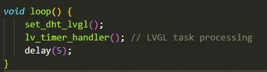
This section is the main body of the program's infinite loop. In each round of the loop, the humidity and temperature update function is called first to read the sensor data and refresh the screen text; then, the lv_timer_handler is executed to handle the internal logic of LVGL, including interface animations, touch detection, screen refresh, and control event responses, which are necessary calls for the normal operation of LVGL; along with a 5ms delay to release the computing power of the MCU and reduce CPU usage.

5. Compile and flash the code
Click the link below and you can access the code for this lesson.

Select the code folder for this lesson, right-click on it, and then choose to open it with VS Code.
Note:
Remember to prepare the hardware environment as per the first point of this course.
Then, following Step 5 “Run the program” from Lesson 1, upload and execute the code in the correct sequence.
Please proceed in the following order: 1 → 2 → 3 → 4 → 5 → 6 → 10

You can observe the current temperature and humidity on the screen.