Lesson4 The temperature and humidity sensor receives data in real time
Welcome to the Lesson 4 of learning.
This lesson will use the IIC interface and of this series of products to collect data from temperature and humidity sensors. In this lesson, we will use the knowledge of LVGL graphics library from Lesson 3 to create an interactive interface.
1. Introduce product ports
USB interface: used for power supply, serial communication, and automatic programming.
UART0-IN interface: supports power supply, serial communication, and entering manual burning mode by pressing BOOT+RESET; Other functions are consistent with the USB interface.
UART0-OUT interface: used for external power supply and serial communication.
UART1-OUT interface: uses soft serial port and supports configuring IO function.
I2C-OUT interface: connects RTC chip, extended IO chip (for screen backlight, touch screen reset, power amplifier pin control) and wireless module, only supports I2C communication.
This is the connection diagram for the temperature and humidity sensor of the 2.4/2.8 size products.

2. UI interface design
The temperature and humidity sensor needs to support IIC communication.
In order to provide everyone with an intuitive observation, I will use LVGL to create an interactive interface.
Open SquareLine Studio. If you haven't installed it, you can review the introduction of LVGL in Lesson 3.
Create "Espressif" project

Note: For this lesson project, use LVGL v9.1.0 for 2.4-inch and 2.8-inch devices.
For 3.5-inch, 4.3-inch, 5.0-inch, and 7.0-inch devices, use LVGL v8.3.11.

Modify the file name and file storage path according to your needs (customization is sufficient)

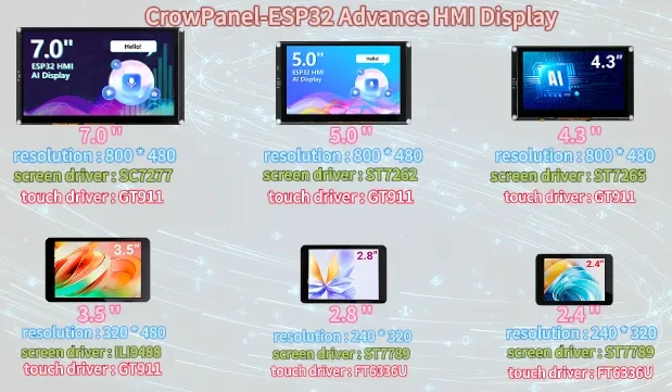
Modify the appropriate resolution based on the different sizes you are using.
If you are using the 2.4-inch version of the product, you will need to set the display resolution to 320 x 280, according to the size comparison chart shown above.
Please note that this project uses the LVGL 9.1.0 version. Make sure to configure the correct LVGL version to ensure compatibility with the provided code and examples.
Finally, click on 'Create' to proceed.

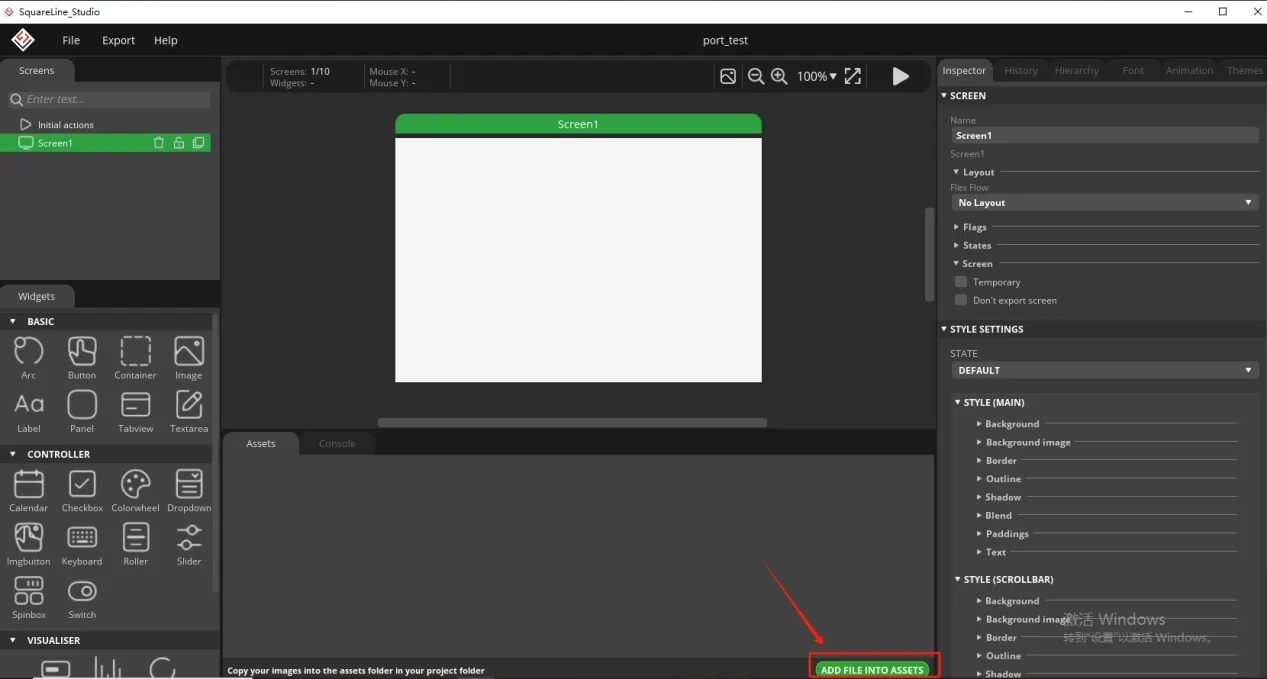
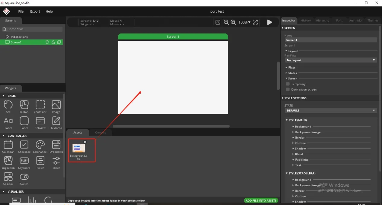
Add the background image we provide based on the resolution required for the size you are using (choose different resolutions for different sizes, refer to the resolution size used for different sizes in Lesson 3)
Here is the corresponding image asset download link for each screen size:

Add background image to the box.
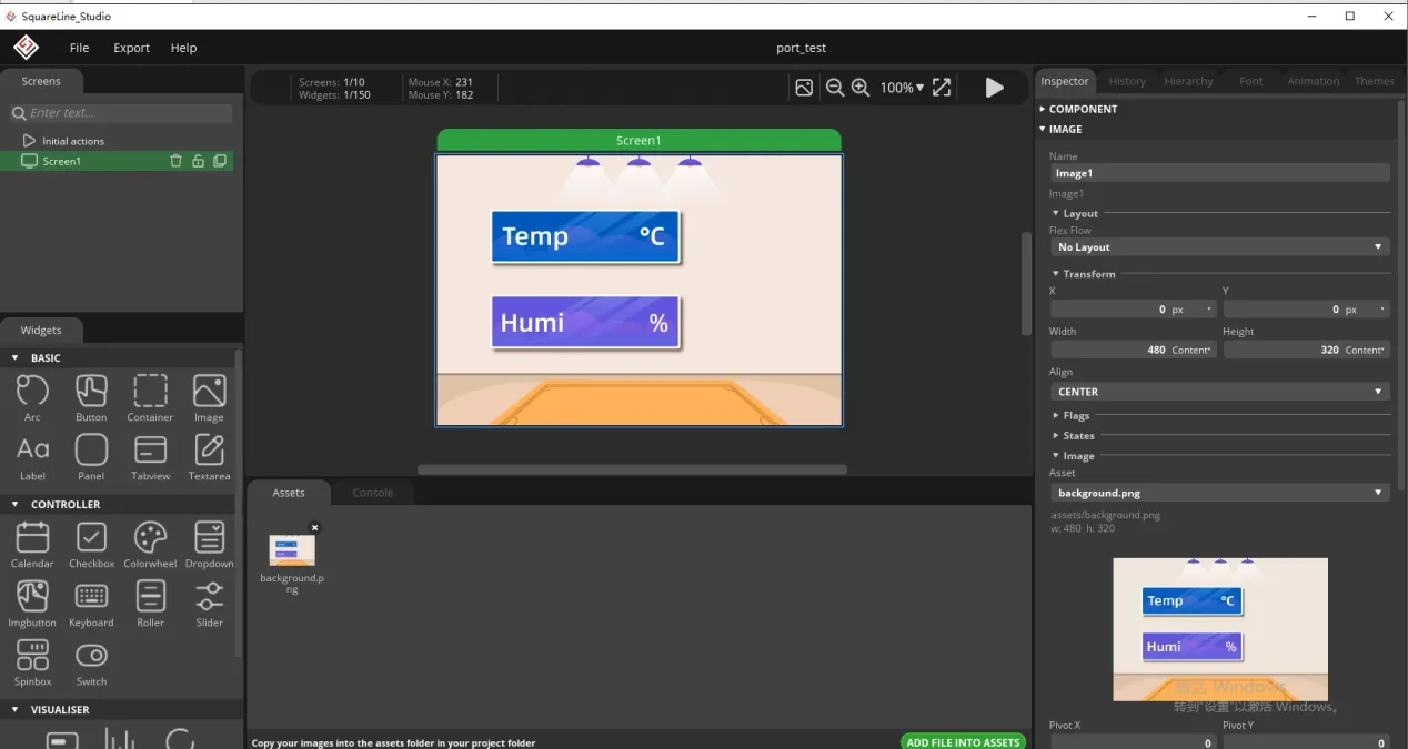
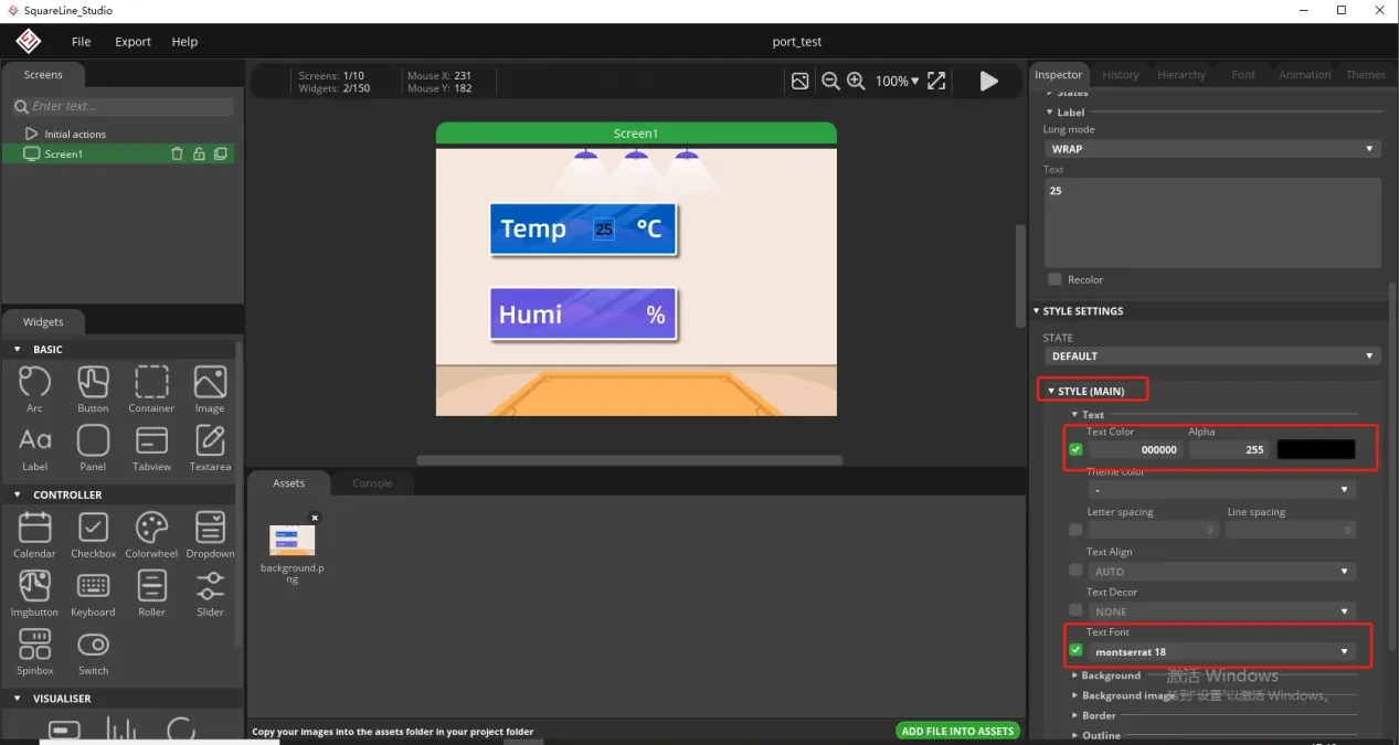
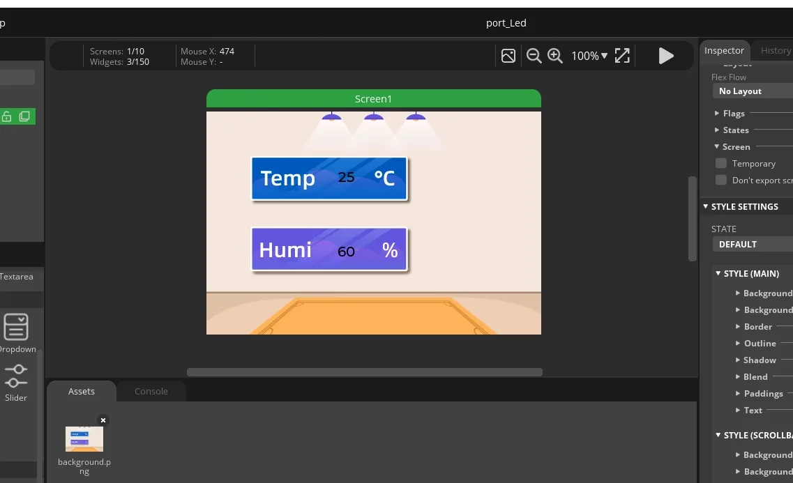
Since we need to display the temperature and humidity values on the screen, we need to add text in the two boxes for temperature and humidity.
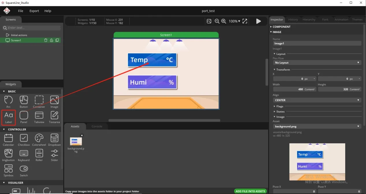
To distinguish between the other text labels that need to be created next, give this label a name to distinguish it.
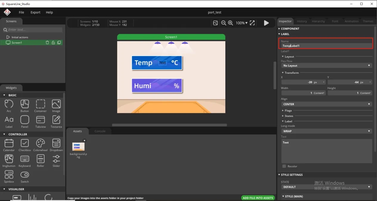
And fill in a default temperature value
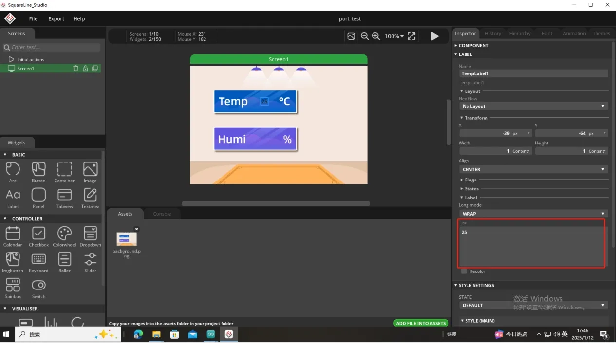
Of course, you can also set the font color and font size here
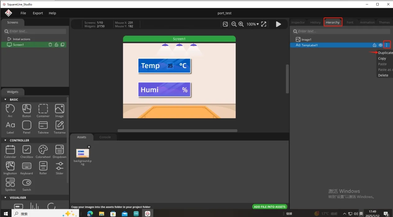
Copy the label just made and display the humidity value
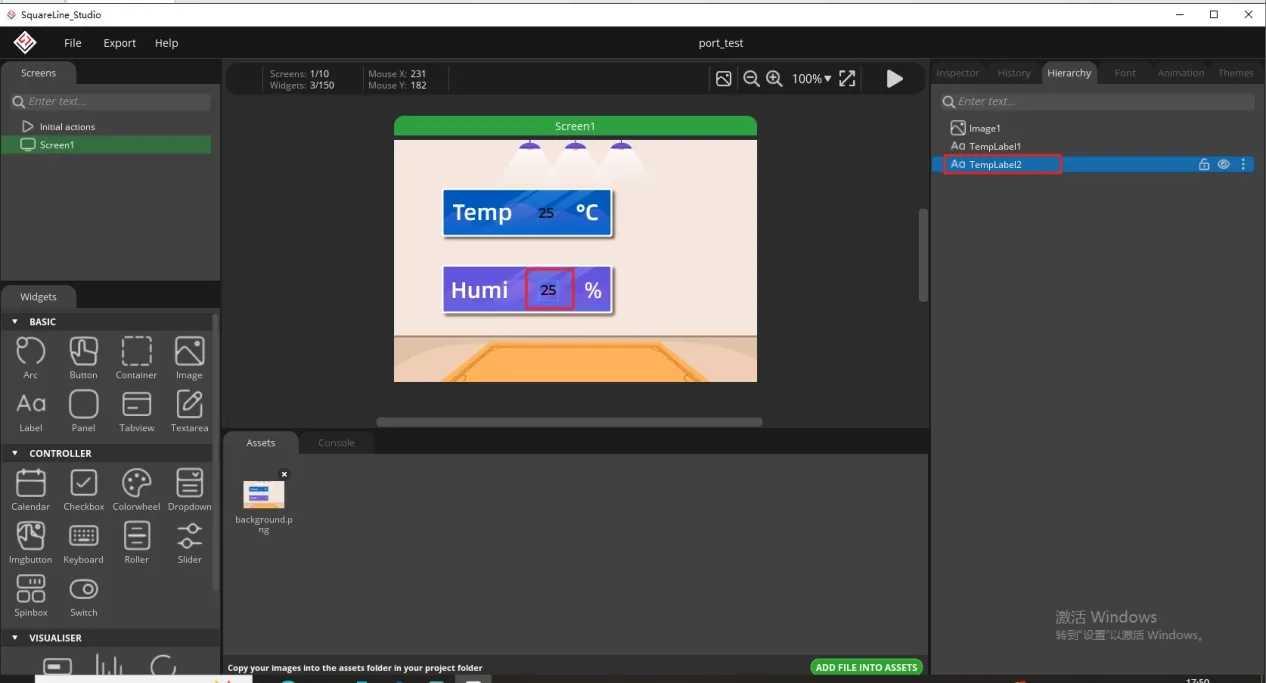
Follow the above steps to modify the humidity label
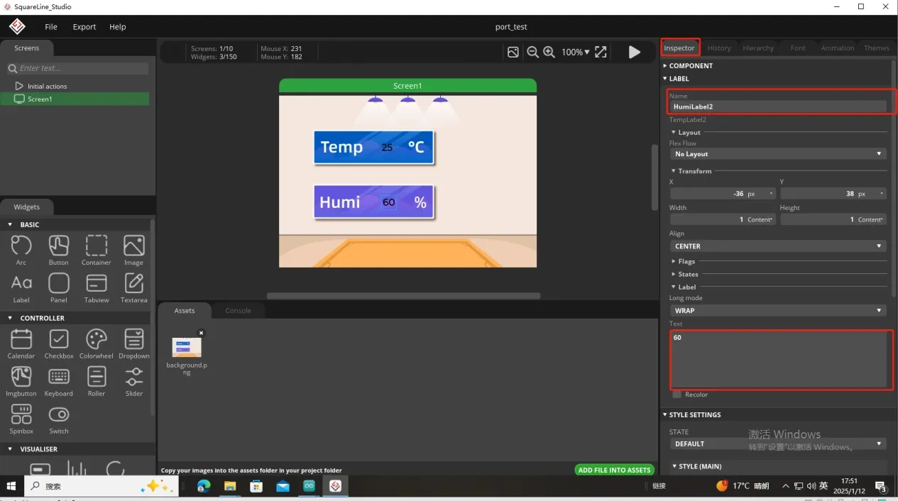
In this way, the display of temperature and humidity is completed.
So, the UI interface we need is completed.
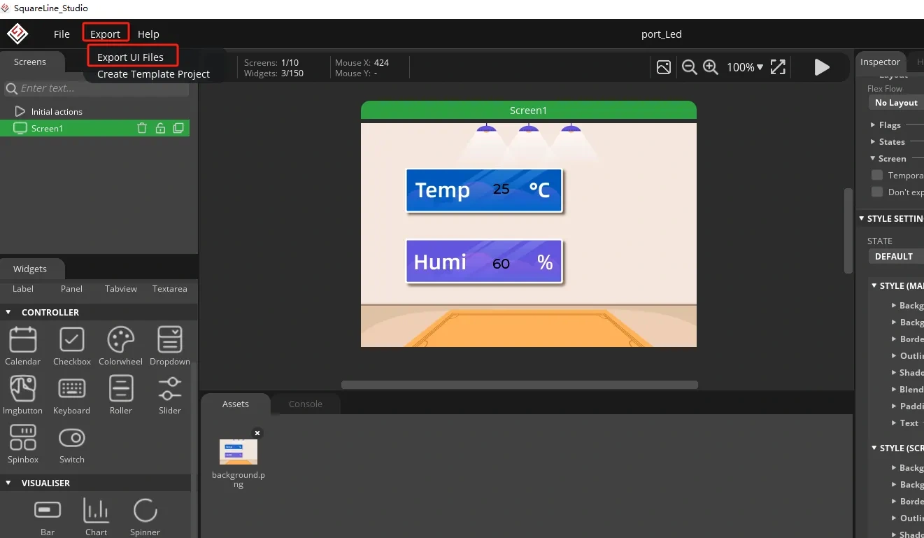
Export the designed UI interface file
How to set the specific export path, please refer to the previous lesson.
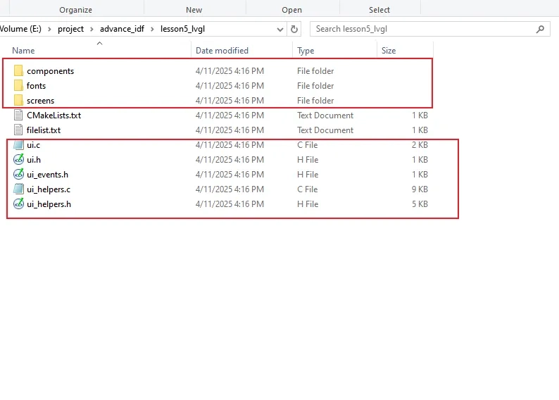
Go to the folder path where you selected to output the UI file.
Click the link below and you can access the code for this lesson.
Code Link:

Next, open the project folder provided for this course using VS Code. Then, copy the .h and .c files generated by LVGL into the corresponding ui folder of the project.

3. Hardware connection
Connect the temperature sensor to the development board and power on the development board.
Note: For the 2.4-inch and 2.8-inch development boards, connect the temperature sensor to UART1-OUT. For other sizes, connect it to I2C-OUT.
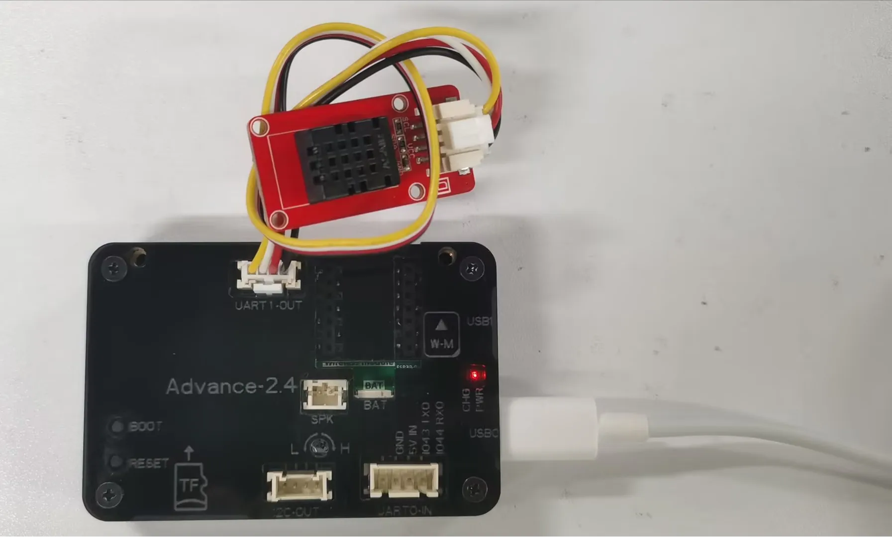
Special Reminder:(The following applies only to 2.8-inch and 2.4-inch products)
The IIC address of the 2.8 and 2.4 touch driver ICs is 0x38, and the IIC address of the DHT20 temperature and humidity sensor is also 0x38. When the DHT20 temperature and humidity sensor is connected to the IIC-OUT interface for use, the two addresses conflict, causing abnormal device usage. The DHT20 temperature and humidity sensor will no longer work, but will ensure the driving of the touch IC.
So in order to make the DHT20 temperature and humidity sensor work, we can connect the DHT20 temperature and humidity sensor to UART1-OUT.
Special note: The UART1-OUT interface allows the use of two or fewer IO interfaces, namely 17 and 18 pins, for your convenience. For example, when connecting a light bulb, 18 pins can be used to receive the initiated control signal. For example, doing digital input/output and analog input/output. There are also some infrared receivers, buzzers, and lights that can be connected. The premise is that you should not use more than 2 IO ports, such as SPI, which requires four IO ports to control and cannot be used.
4. Explanation of the code project
This project is developed and run on ESP-IDF version 5.5.4.
Let's take a look at the framework of this project.
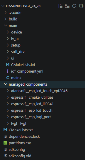
- main: The main program directory, with main.c being the sole entry point of the program;
- main/setup: The module for initializing the underlying bus, containing the implementation of hardware initialization for setup_gpio/spi/i2c;
- main/device: The hardware drivers for peripherals, including the underlying drivers for LCD screens and GT911 capacitive touch chips;
- main/soft_drv: The LVGL adaptation layer, connecting the underlying screen/touch driver with the LVGL graphics library;
- main/lv_ui: The UI interface code generated by the LVGL editor, storing page and control logic;
- CMakeLists.txt, idf_component.yml: The compilation configuration files for ESP-IDF, managing compilation dependencies and component imports.
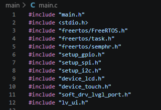
This section imports all the project dependency header files. The main.h file stores the common data types of the project and the interface definition for the DHT20 sensor; the stdio.h file provides string formatting printing; the FreeRTOS series of header files provide APIs for task creation, mutual lock synchronization, and system delay; the setup/device/soft_drv/lv_ui series of header files continue to use the previous modular screens, I2C, SPI, and LVGL underlying drivers, reuse the original LCD, touch hardware initialization code, and do not need to rewrite the underlying logic of the screen; on this basis, a new temperature and humidity collection business is added.
This section defines the global variables shared by the entire program, which are used for data interaction in multiple tasks and UI control management:
- read_data_h: The handle of the DHT20 sensor acquisition task, which can be used for subsequent task suspension, deletion, and priority modification;
- data_mutex: A FreeRTOS mutex lock, which solves the data tearing problem caused by simultaneous reading and writing of the temperature and humidity structure by the sensor acquisition task and the interface refresh task, and ensures the atomicity of shared data reading and writing;
- sensor_data_t is a custom structure, serving as a data exchange buffer for the two tasks, storing floating-point temperature and humidity;
- measurements is a static global structure, initializing the default values of temperature and humidity as 0;
- label_temp / label_humid are global pointers of LVGL text controls, corresponding to the display text of temperature and humidity on the screen, allowing the refresh task to modify the text content at any time.

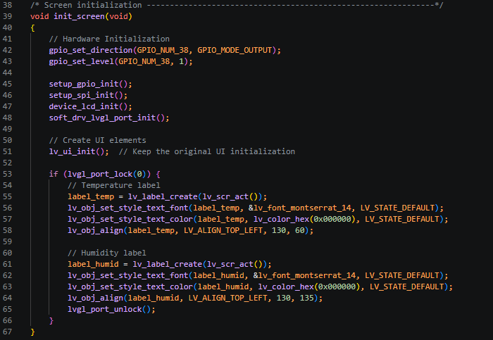
This section encapsulates the entire screen and LVGL initialization logic, replacing the scattered hardware initialization code in the original app_main. The execution flow is clearly layered:
- First, configure the GPIO38 pin for the screen backlight as an output and pull it high. Power-on to light up the backlight, avoiding the flickering sequence problem during screen initialization;
- Then, call the original modular low-level initialization: global GPIO, SPI screen bus, LCD screen hardware, LVGL hardware adapter layer. Reuse the previously mature screen driver code;
- Execute lv_ui_init() to load the basic UI interface prepared by the LVGL editor;
- The LVGL interface is not thread-safe. Lock the graphic resources through lvgl_port_lock. Create two text controls on the current screen: Temperature text: 14-point font, black, coordinates X130 Y60; Humidity text: 14-point font, black, coordinates X130 Y135;
- Release the LVGL graphic lock, save the two control pointers to global variables, and subsequent refresh tasks can directly modify the text.
This section is an independent FreeRTOS background task, specifically responsible for reading the cached temperature and humidity data and refreshing the screen UI. The cycle period is 500ms:
- Define the character cache to store the formatted temperature and humidity string;
- Try to acquire the mutex lock, waiting for a maximum of 100ms. Once the lock is obtained, read the temperature and humidity from the global structure, retain one decimal place and convert it to a string. Immediately release the mutex lock after reading to reduce the lock occupancy time without blocking the sensor task;
- Again lock the LVGL graphic resources, assign the formatted numeric string to the two text controls on the screen, refresh the screen values, and release the graphic lock after the refresh is completed;
- Delay for 500ms to enter the next round of refresh, reduce the SPI screen refresh frequency, and reduce the bus occupancy.

This section is for the independent sensor acquisition task. The I2C type DHT20 temperature and humidity sensor is read once every 2 seconds:
- Define a structure to store the original sensor reading data;
- Call the DHT20 reading function. When the data is valid (temperature is greater than or equal to 0), try to obtain the mutex lock;
- After obtaining the lock, write the latest temperature and humidity to the global shared buffer. Immediately release the mutex lock after writing;
- If the reading fails, directly skip this data update and wait for 2 seconds for the next acquisition. The DHT20 chip recommends a collection interval of 2 seconds to avoid overloading the chip.

This section is the sole entry point for powering on ESP-IDF. The execution sequence is as follows:
-
Call init_screen() to complete the initialization of backlight, screen, LVGL layer, basic UI, and temperature/humidity text controls all at once;
-
Initialize the I2C DHT20 temperature/humidity sensor hardware;
-
Create a mutex lock data_mutex for data synchronization protection between two tasks;
-
Create two independent FreeRTOS tasks, allocating 2048 bytes of stack space:
Sensor acquisition task: priority 3, higher than the interface refresh task, ensuring that temperature/humidity acquisition will not be preempted by interface refresh;
Interface refresh task: priority 2, responsible for updating screen values;
- The main thread enters a permanent blocking delay, no longer executing any business logic, and all acquisition and refresh logic is handed over to the background task scheduling.

5. Compile and flash the code
Click the link below and you can access the code for this lesson.

Select the code folder for this lesson, right-click on it, and then choose to open it with VS Code.
Note:
Remember to prepare the hardware environment as per the first point of this course.
Then, following Step 5 “Run the program” from Lesson 1, upload and execute the code in the correct sequence.
Please proceed in the following order: 1 → 2 → 3 → 4 → 5 → 6 → 10

You can observe the current temperature and humidity on the screen.