Lesson3 Use SquareLine Studio and LVGL libraries to create a UI interface to light the lights
Welcome to the third lesson of learning. I believe that after completing the last two lessons, everyone has gained a deeper understanding of our product. Next, I will lead you to the second application case of the Advance series products - Display the interface by calling LVGL technology and control the on - off state of the small light bulb.
1. Using previous preparations
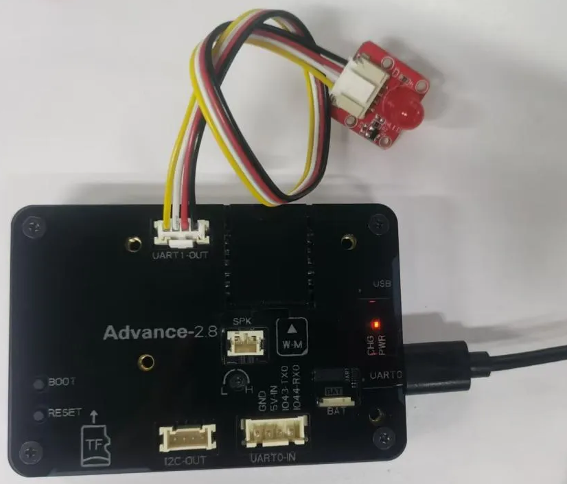
Connect the Crowpanel-Advance-HMI-AI-Display to the computer with a Type-C cable.
Connect the light bulb at the UART1-OUT interface.
Observing the schematic diagram of this size, it is known that the pin for UART1 to control the light bulb to turn on and off is 18
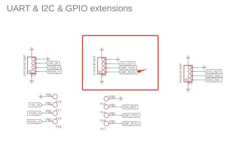
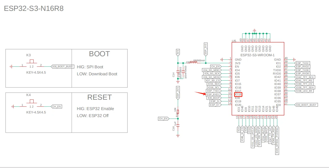
So in the code, set pin 18 as the output mode.
2. Introduce LVGL
LVGL (LittlevGL) is an open-source, lightweight, high-performance embedded graphics library designed specifically for devices with limited resources. It supports multi platform porting, provides rich controls, animations, touch support, and highly customizable styles, suitable for fields such as smart homes, industrial equipment, medical instruments, etc. LVGL is centered around modular design and can run on bare metal or operating systems, accelerating GUI development through powerful community support and tools such as SquareLine Studio.
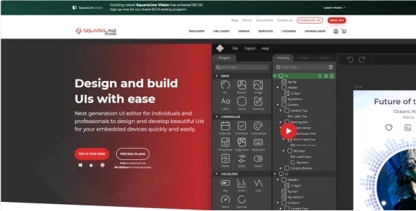
SquareLine Studio is a next-generation user interface (UI) solution for individuals and professionals, allowing users to quickly and easily design and develop aesthetically pleasing UI for embedded devices. This software provides integrated design, prototyping, and development capabilities, supporting the export of platform independent C or MicroPython code for LVGL (Lightweight Graphics Library), which can be compiled and run on any vendor's device.
3. Install SquareLine Studio
3.1 Installation Guide
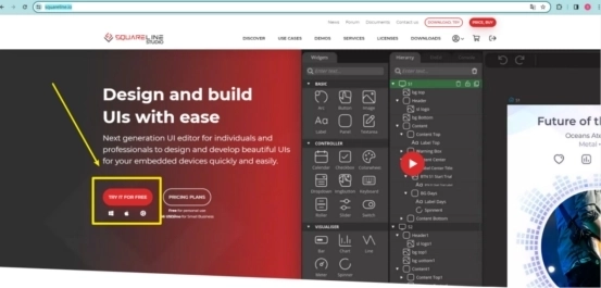
Enter the https://squareline.io/ to download the SquareLine installation file.
Download the version 1.4.0
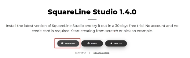
Double-click the setup.exe file.
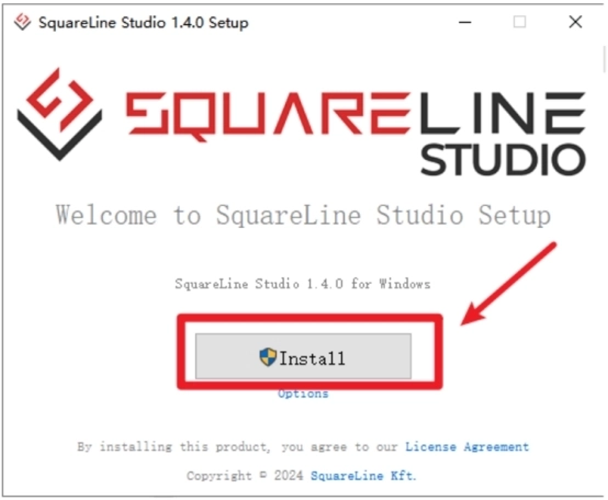
Click install.
Wait for installation.
Installation finish.
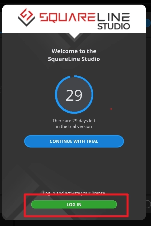
There is a 30-day trial period for the first time you use it. Please follow the prompts to register an account. You will continue to use it when you log in to your account next time.
3.2 Software Function Introduction
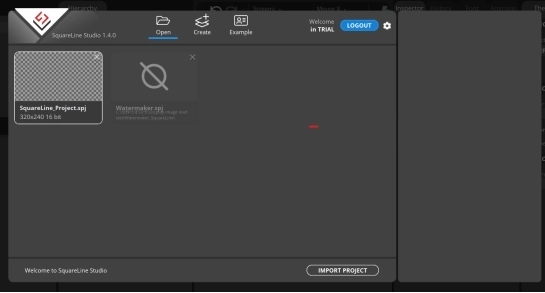
Open the software
The historical project page: open the project built earlier.
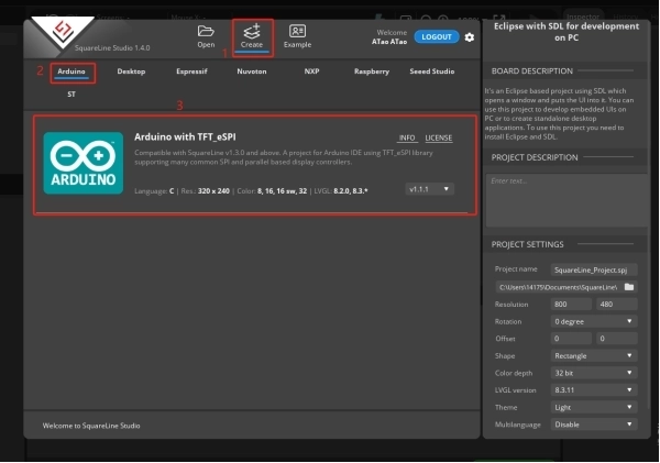
Create a project page: choose different platforms according to different hardware of the project.
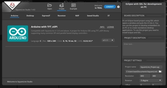
When select the Arduino framwork, there's only one option "Arduino with TFT_eSPI". By choosing this, the squareline studio will generate a template code suitable for the TFT_eSPI library. However, squareline studio not only supports the TFT_eSPI library, it supports a variety of libraries to suit different hardware and application needs. For example, Adafruit_GFX library, LovyanGFX etc.
After using SLS to generate UI code, we then use different graphics libraries according to different hardware and modify the corresponding code to display the content you design.
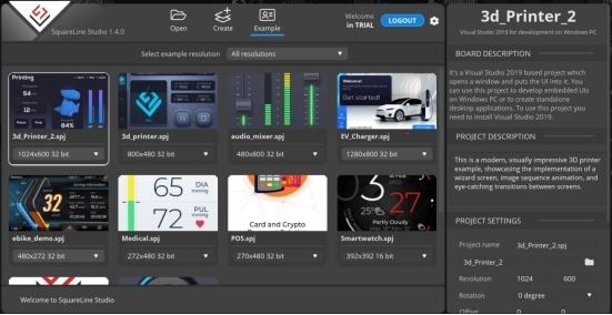
Example page. This page has several official examples for reference.
The project settings bar is used to make basic settings for the project, including property settings such as project name, screen size, display angle, etc.
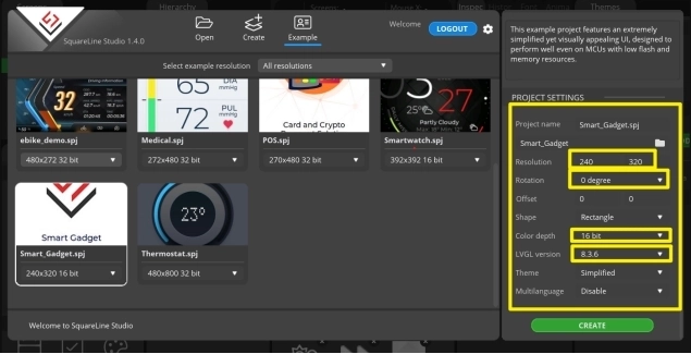
Note:Please select the corresponding resolution and color depth according to the screen specifications.
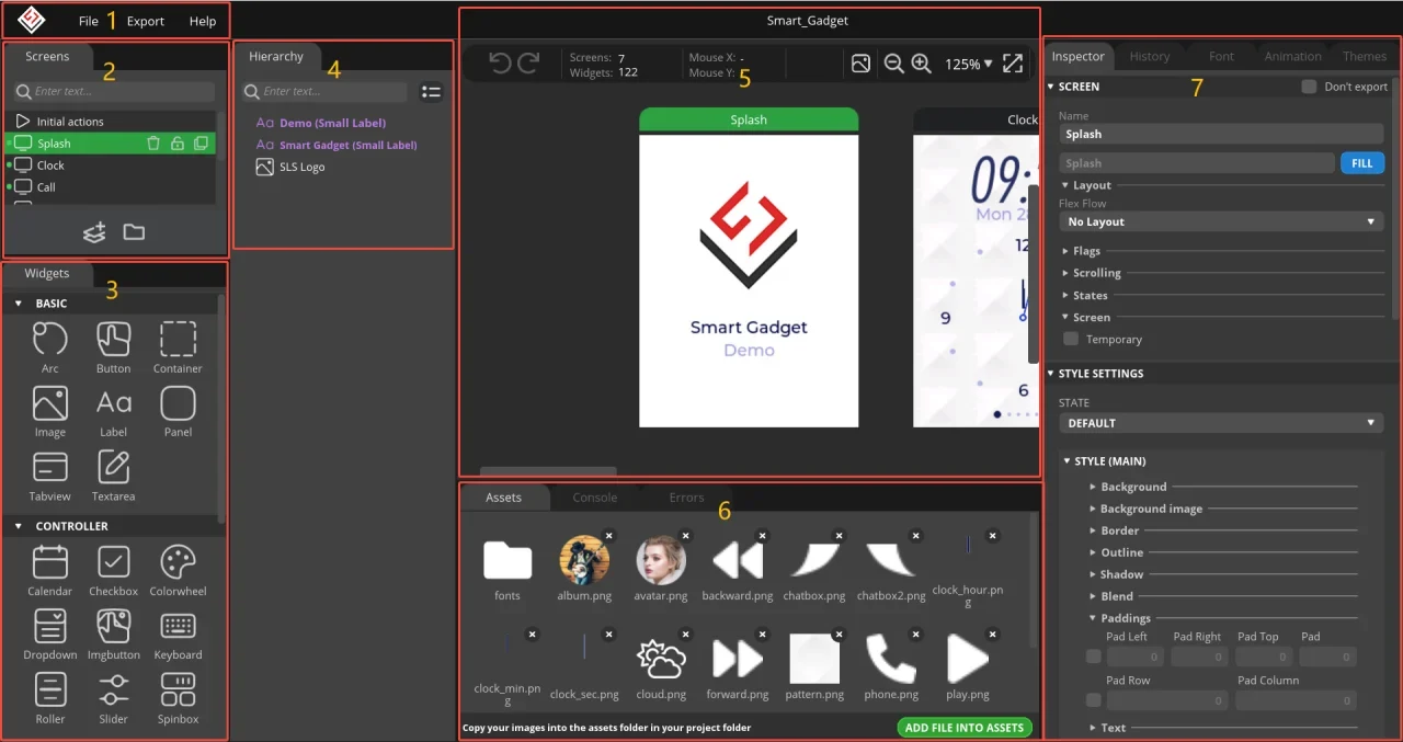
①Toolbar, including File, Export, and Help. Basic file operation bar, create or open files, export UI files and other operations. Click help and there are related introductory documents.
②Screen bar, the project screen will be listed here.
③Widget area, all widgets are here and can be selected and used according to project needs.
④Hierarchy area, it will show every widget used in each screen.
⑤This area shows the actual display effect, you can adjust the widgets or screen here.
⑥Material column, the added materials are displayed here.
⑦Setting bar, where you can make basic settings for each part, including the basic attributes and trigger operations of the part.
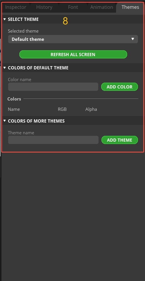
⑧Theme bar, different themes can be set.
4. Use SquareLine Studio to create UI control interfaces
4.1 Create a new SquareLine Studio project.
Firstly, open the SquareLine Studio software and create a case study
Choose the correct resolution based on the different sizes you are using
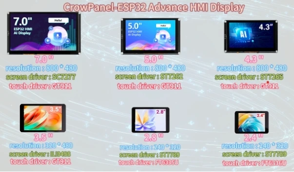
Here, I take a 2.8-inch screen as an example. After determining the resolution, I fill it in.
If you are using the 2.4 / 2.8-inch version of the product, you will need to set the display resolution to 320 x 280, according to the size comparison chart shown above.
Please note that this project uses the LVGL 9.1.0 version. Make sure to configure the correct LVGL version to ensure compatibility with the provided code and examples.
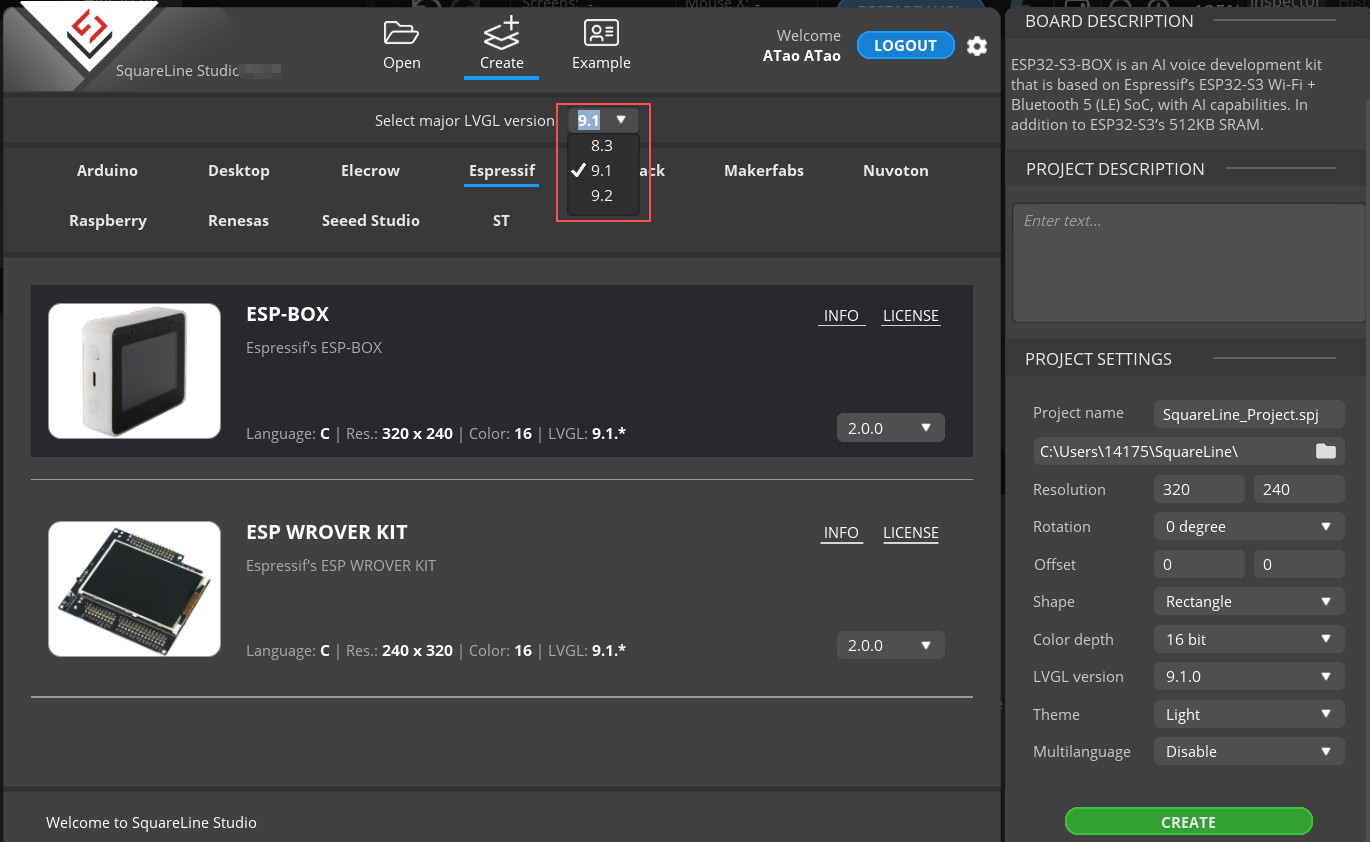
After selecting the parameters, click Create

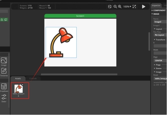
Open the photo of the desk lamp we provided and add it in. (Of course, you can also choose the image you want to use)
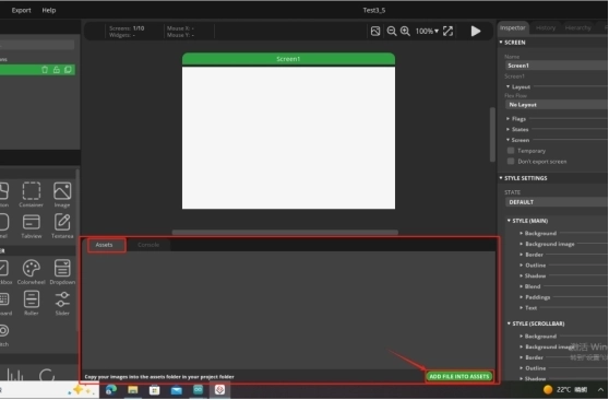
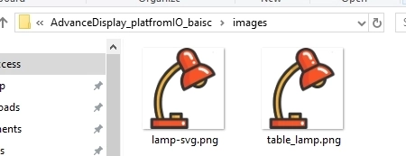
The images can be found at the following location:
Just use the pictures here.
The lamp-svg image size is available for both 2.4-inch and 2.8-inch screens.
The table_lamp image sizes are available for 3.5-inch, 4.3-inch, 5.0-inch, and 7-inch screens.
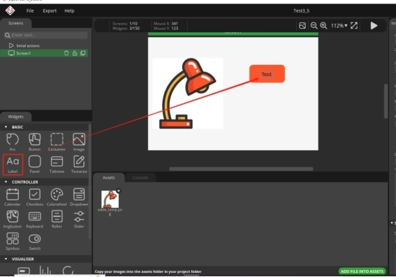
After adding it, drag and drop the image in.
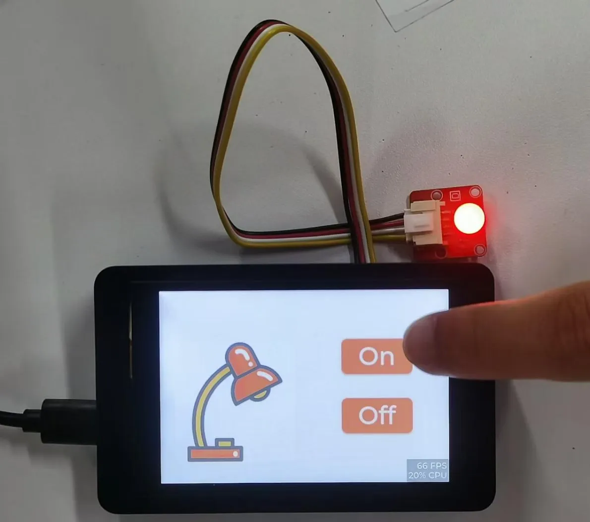
The task we need to complete is to turn on and off the lights by clicking on the buttons on the graphical interface. So we need to design two buttons
From the left sidebar, select Button and drag it into the interface.
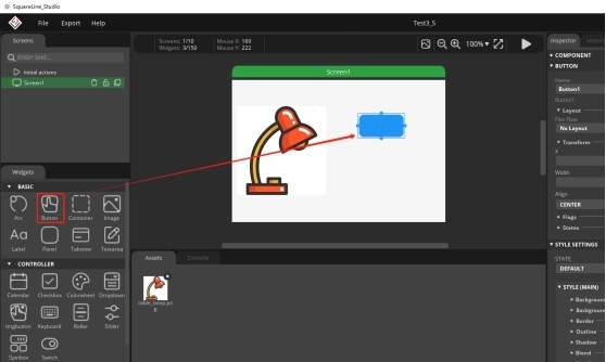
You can adjust the border of the button with the mouse, which can adjust the size of the button, and you can also drag and drop the button to adjust its position.
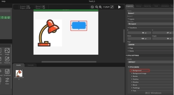
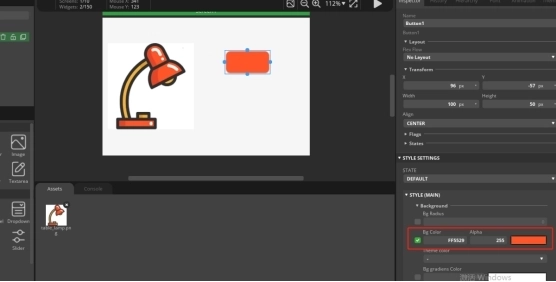
Then, by selecting Background, choose the background color of the Button.
We have made the button patterns, and now we need to add labels to the button patterns in order to distinguish their functions.
Drag and drop from the left sidebar, select Label, and drag into the interface.
Modify the text content of the label
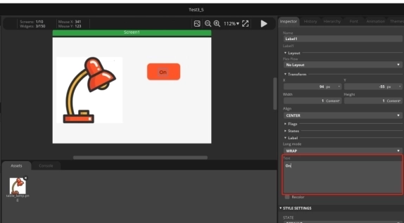
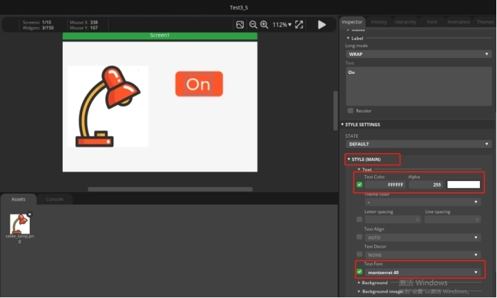
And modify the font size and text color of the text
The Button and Label have been designed. Click on the Hierarchy in the right-hand column and drag the Label onto the Button line to merge them into one.
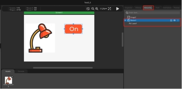
At this point, if you drag the buttons again, you will find that they are dragged together
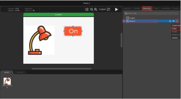
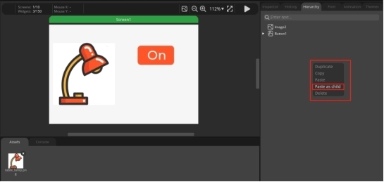
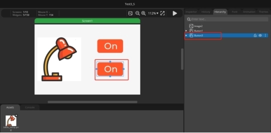
Next, we will copy a completed button, right-click, and paste it in.
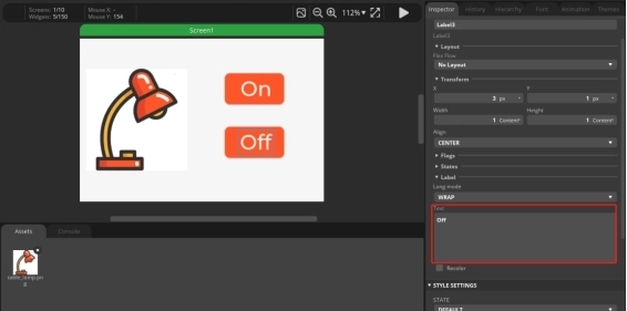
Click the second button ON to change the text content to Off. Used to achieve the effect of turning off lights.
4.2 Add functions to the buttons to enable them to turn on and off lights
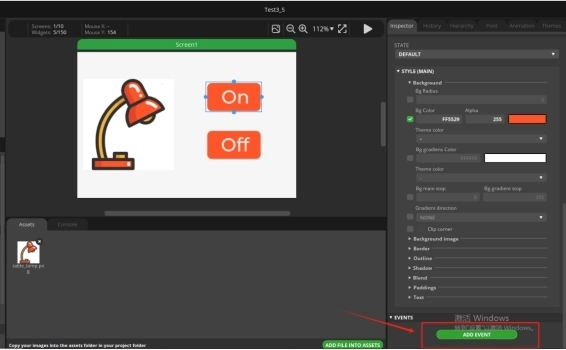
Select 'event' to add in the right sidebar.
Select 'released' as the triggering condition and 'Call function' as the action.
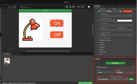
After selecting, click ADD.
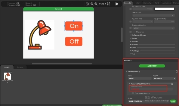
And add a function name to the CALL Function. (Customization is sufficient)
Similarly, add an event to the Off button. The operation process is the same as above.
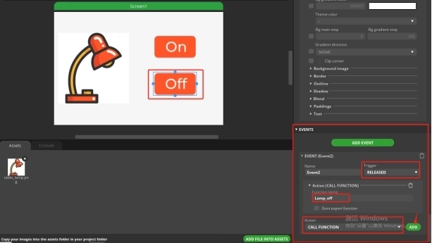
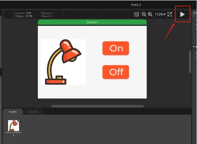
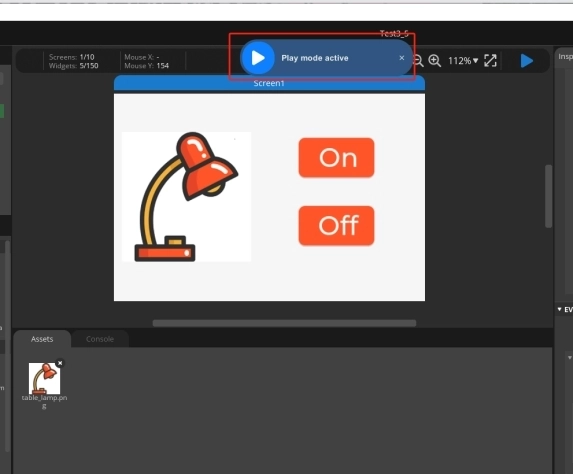
After adding, run
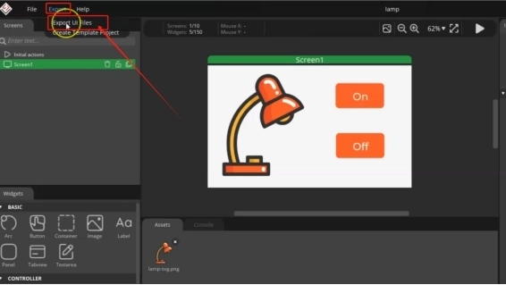
4.3 UI interface design completed, exporting UI files for easy use in subsequent code
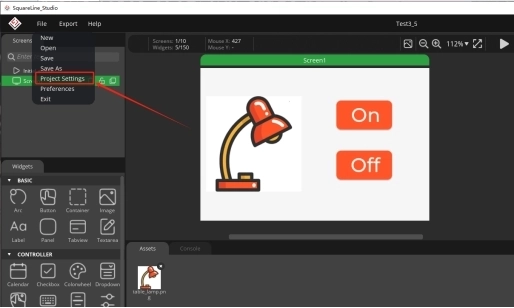
Click on Project Setting
Set export path.
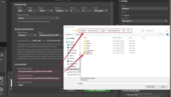
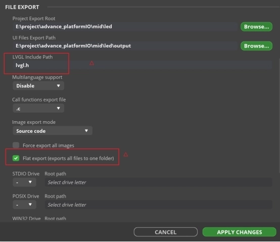
Complete the setup and export file.
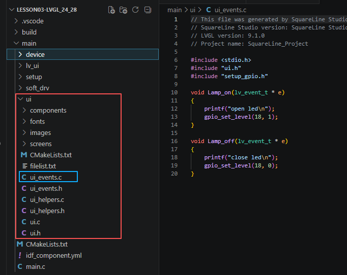
Next, open the project folder provided for this course using VS Code. Then, copy the .h and .c files generated by LVGL into the corresponding ui folder of the project. You can download the complete project code from the link provided below.
5. Explanation of the code project
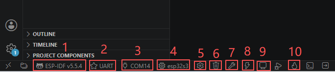
This project is developed and run on ESP-IDF version 5.5.4.
Let's take a look at the framework of this project.
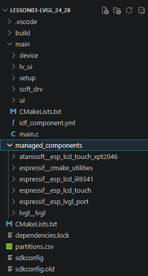
- main: The main program directory, with main.c being the sole entry point of the program;
- main/setup: The module for initializing the underlying bus, containing the implementation of hardware initialization for setup_gpio/spi/i2c;
- main/device: The hardware drivers for peripherals, including the underlying drivers for LCD screens and GT911 capacitive touch chips;
- main/soft_drv: The LVGL adaptation layer, connecting the underlying screen/touch driver with the LVGL graphics library;
- main/lv_ui: The UI interface code generated by the LVGL editor, storing page and control logic;
- CMakeLists.txt, idf_component.yml: The compilation configuration files for ESP-IDF, managing compilation dependencies and component imports.
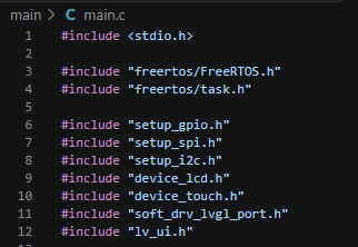
This section introduces all the project header files based on the dependency hierarchy:
- System foundation header files: stdio.h provides serial port printing; FreeRTOS header files provide operating system delay and multi-task scheduling capabilities;
- Low-level bus module header files: corresponding to the setup folder, they encapsulate GPIO, SPI (screen bus), and I2C (touch screen bus) hardware initialization;
- Peripheral driver header files: corresponding to the device folder, they provide hardware driver interfaces for LCD color screens and capacitive touch chips;
- Graphics adaptation layer header files: corresponding to the soft_drv folder, they implement LVGL screen refresh callbacks and touch input callbacks, serving as an intermediate bridge between the underlying hardware and the LVGL library;
- Interface business header files: corresponding to the lv_ui folder, they store the complete UI interface initialization code generated by LVGL tool drag-and-drop.
All the detailed functions are split into independent modules. In main.c, only the exposed initialization functions are called, making code reuse, debugging, and hardware replacement more convenient.
This section prioritizes the initialization of the screen backlight pin, which is a crucial aspect of the power sequence on the screen: GPIO18: A general output pin, reserved for the use of LED light control pins; GPIO38: The screen backlight control pin, configured as an output and directly pulled to a high level, turning on the backlight immediately upon power-on; Placed at the very beginning of all initializations, it resolves the timing issue of "initializing the screen hardware before turning on the backlight, resulting in a blank screen during startup".
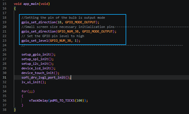
The initialization sequence strictly follows the bottom layer → top layer, following the rule of dependencies being performed before others, and corresponds one-to-one to the project folders:
- setup_gpio_init(): Calls the code of the setup module, globally initializing all GPIO pins' pull-up and mode settings used by the project;
- setup_spi_init(): Initializes the SPI hardware bus, used to drive the LCD color screen;
- setup_i2c_init(): Initializes the I2C hardware bus, used to read the GT911 capacitive touch chip;
- device_lcd_init(): Calls the device screen driver, initializing the screen timing, resolution, and video memory;
- device_touch_init(): Calls the device touch driver, initializing the I2C touch IC, obtaining touch coordinates;
- soft_drv_lvgl_port_init(): Calls the soft_drv adapter layer, registering screen refresh and touch input callbacks to LVGL, connecting the hardware and the graphics library;
- lv_ui_init(): Calls the lv_ui interface module, loading the pre-designed graphical interface, buttons, and text controls.
This sequence cannot be reversed: Without initializing the bus, the peripheral driver will report an error; Without initializing the screen / touch, the LVGL adapter layer cannot register the hardware; Without the adapter layer being ready, the UI interface cannot be rendered on the screen.

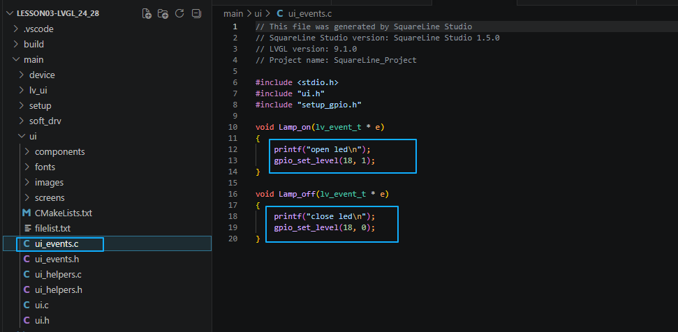
Finally, if you want to control the LED connected to the UART1-OUT interface by tapping the On and Off buttons on the screen, you need to implement the callback functions defined in SquareLine Studio inside the ui_events.c file located in the ui folder under the main directory.
6. Compile and flash the code
Click the link below and you can access the code for this lesson.
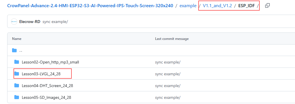
Select the code folder for this lesson, right-click on it, and then choose to open it with VS Code.
Note:
Remember to prepare the hardware environment as per the first point of this course.
Then, following Step 5 “Run the program” from Lesson 1, upload and execute the code in the correct sequence.
Please proceed in the following order: 1 → 2 → 3 → 4 → 5 → 6 → 10
After completing Step 10, you will be able to see your LVGL interface displayed on the screen. In addition, tapping On will turn on the LED, while tapping Off will turn it off.