Lesson13 DIY Electronic Control Terminal on ESP32 Display with Squareline Studio
Project introduction:
This project uses Squareline Studio to create an ESP32-based electrical control cabinet terminal, and users can control the LED light on/off by clicking the switch button on the screen.
Introduction to Knowledge Points:
The following is a basic introduction to the functions used in the project:
void lv_slider_set_value(lv_obj_t * slider, int16_t value, lv_anim_enable_t anim_en)
In this function, the first parameter "slider" is a pointer to the slider control to set the value, the second parameter "value" is the value to set, and the third parameter "anim_en" specifies whether to use animation effects to change the value of the slider. If set to LV_ANIM_OFF, no animation effect will be used, and the value of the slider will be set directly to the specified value.
For example, to set the value of a slider control named "ui_Slider2" to 50 without animation effect, the following code can be used:
lv_slider_set_value(ui_Slider2, 50, LV_ANIM_OFF);
Note that you need to use the lv_slider_create() function to create the slider control and add it to the screen object before you can use lv_slider_set_value() to set its value.
lv_img_set_src(lv_obj_t * img, const void * src)
The lv_img_set_src(lv_obj_t * img, const void * src) function is used to set the source data of the image object. The "src" parameter can be image source data in various formats, such as:
- File path of an image file stored in the file system.
- Pointer to a memory block containing image data in a format supported by LVGL.
- URL of an image file that can be accessed through the network.
After setting the image source data, LVGL will automatically decode and display the image on the image object specified by the "img" parameter. It is worth noting that the "src" parameter is declared as const void , which means that this function will not modify the data pointed to by "src". For functions that only need to read input data, this is a good practice because it can prevent the function from accidentally modifying the input data.
Overall, the lv_img_set_src() function is a useful function for displaying various image data on embedded systems and displays, allowing developers to display various image data on embedded systems and displays.
**Required hardware modules:*
A linear potentiometer is a variable resistor that is usually composed of a sliding electrical contact and a fixed resistor. When the sliding electrical contact moves along the surface of the resistor, the resistance value changes accordingly. Linear potentiometers are commonly used to control continuous parameters such as the brightness of lights and the volume of audio.
A collison switch is a mechanical switch that is typically used to detect collisions or impacts between objects. When an object hits the switch, the mechanical parts inside the switch trigger and close or open the circuit. This switch is usually used in safety systems or automation control systems to detect abnormal conditions in time and take corresponding measures. For example, the airbag in the car uses the crash switch to detect whether the vehicle has collided, so that it can be inflated in time to protect the passengers.
Both of these control components have wide applications in electronic products. For example, in audio systems, linear potentiometers are used to control volume and tone, while touch switches are used for functions such as power control and mode selection.
Project steps:
Note: First add the provided image material files!
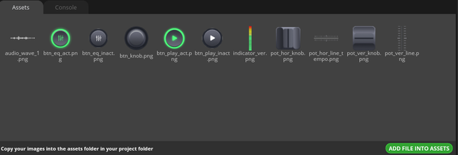
1 Create a new project in Squareline Studio as before. First select the Arduino module, and then perform simple settings for the project, such as project name and display size. Click Create.

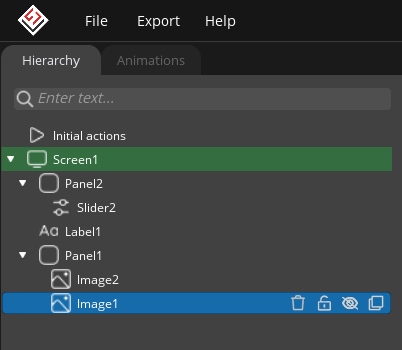
2 Add panels, including panel, label, slider, and image components, adjust and set the position according to the diagram hierarchy.
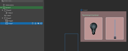
3 Arrange the components according to the diagram position and add image materials to the image components. (Note: one of the images is not displayed on the screen, it is only used to introduce the image material. Select the Light on file for the image material.)
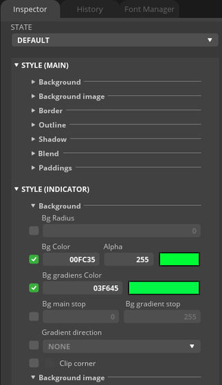
4 Perform simple settings for the slider component, or set different properties according to your own preferences.

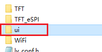
5 Copy the generated UI file to the UI folder in the library.
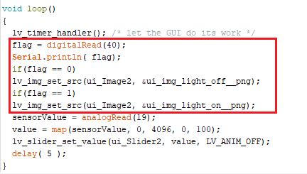
6 Add two variables in the arduino main program file for image switching and slider sliding changes.

7 pin 40 to input mode in setup().

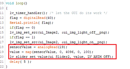
8 In the loop main program, set the program to control the image and slider.
- First, read the value of pin 40, and then judge. When the value equals 0, use the lv_img_set_src function to set the display of the light off image; when the value equals 1, use the lv_img_set_src function to set the display of the light on image.
- Read the analog value of pin 19, convert it, and use the lv_slider_set_value function to change the value of the slider.
Operating effect:
After the program is successfully downloaded, check the effect on the screen.


Summary:
This project helps beginners to quickly understand the UI interface of external sensor control, and through relevant functions, modify it to achieve the function of sensor control interface control. In practical applications, it can be modified and extended according to needs, and more settings and functions can be added.
HMI Display Tutorial Contents
- Lesson01 Introducing the ESP32 Display series and environment configuration
- Lesson02 Start the ESP32 DISPLAY GUI drawing via LovyanGFX Graphics Library
- Lesson03 How to Display Pictures on ESP32 Boards
- Lesson04 LVGL Basics: How to install LVGL for ESP32 Displays
- Lesson05 Introduction to the 5 categories of LVGL GUI library Widgets
- Lesson06 Use Squareline Studio to start your 1st human machine interface project
- Lesson07 How to implement text information input with Squareline Studio
- Lesson08 How to make the menu and a progress bar with Squareline Studio
- Lesson09 How to make an analysis report on ESP32 Display
- Lesson10 Create a 3D Printer UI Project on ESP32 Display
- Lesson11 How to Make a Mixer Interface on ESP32 Display
- Lesson12 Make Your ESP32 Display the Lantern Control terminal
- Lesson13 DIY Electronic Control Terminal on ESP32 Display with Squareline Studio
- Lesson14 Create Car Control Screen on ESP32 Display: A Step-by-Step Guide
- Lesson15 Smart Agriculture Monitoring: IoT-Based Real-Time ESP32 Display Project
- Lesson16 ESP32 Display for Smart Home Central Control: A Home Automation Solution
