Lesson5 SD card stores images and displays them locally
Welcome to the application tutorial of Lesson 5. The effect to be achieved in this lesson is to store the images that need to be displayed on the SD card and display them on the CrowPanel ESP32 Advance HMI.
This lesson requires everyone to prepare an SD card to store pictures. And a card reader.
1 Select the photos you want to display on the browser and save them on the desktop (the save path can be customized)

2 Modify the resolution of the image based on the size of the product you are using.
This is the resolution size we accept for each size product.

Here, for large-sized products, I will take the 7.0-inch product as an example to introduce how to modify the resolution of images.
The resolution of the 7.0-inch product is 800*480.
(Note: The image resolution of 7.0-inch, 5.0-inch, and 4.3-inch products is consistent, and the code and image can be used interchangeably.)
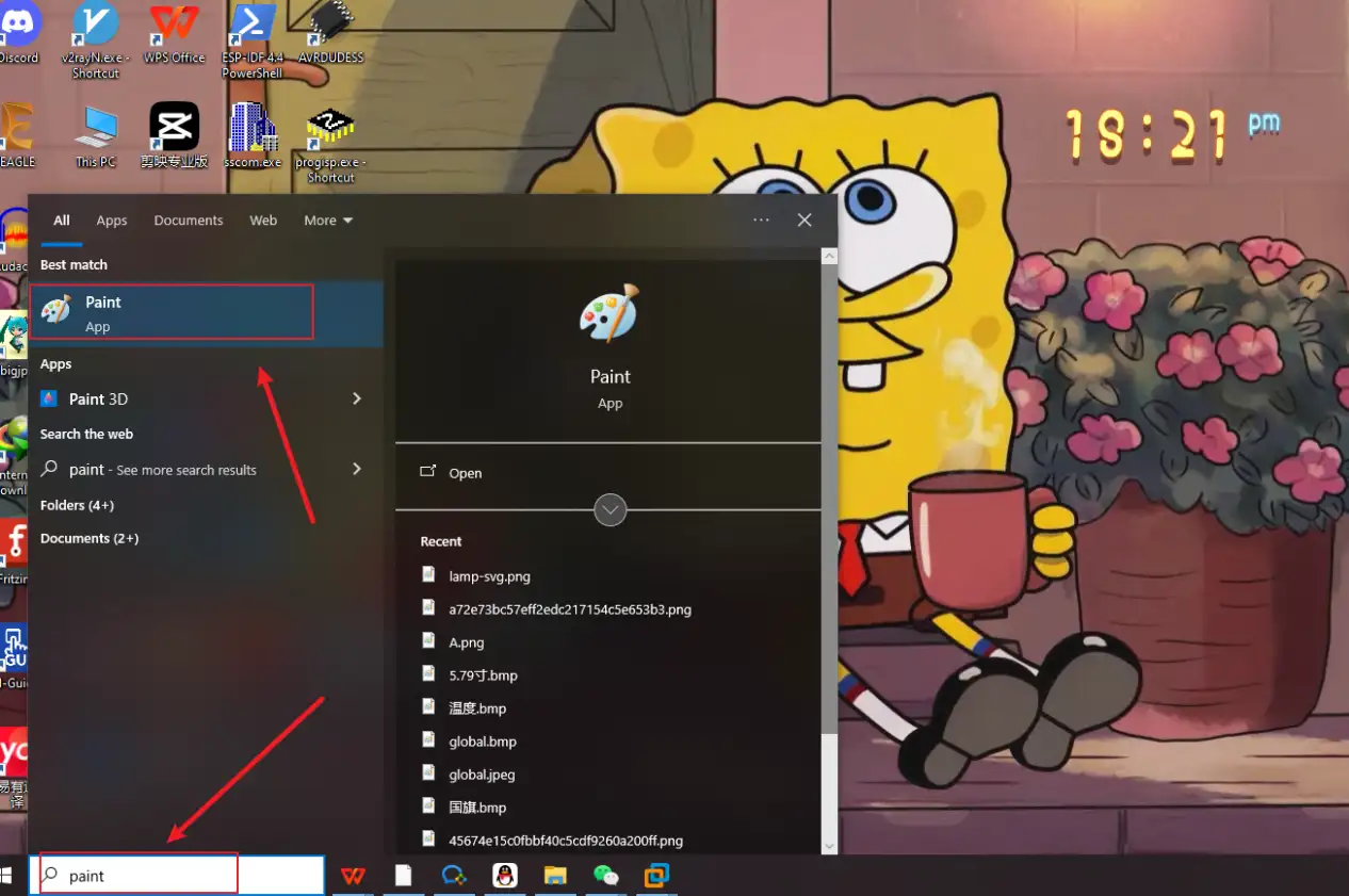
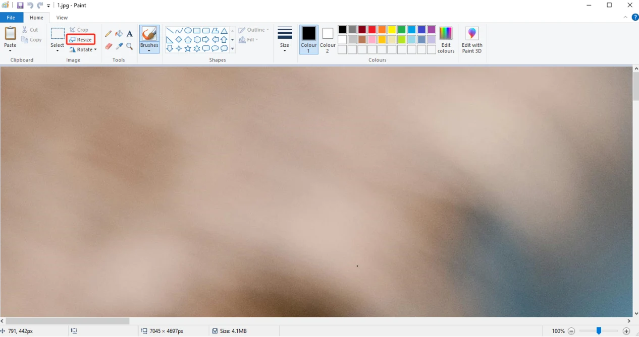
First, open the "paint" tool on the computer.
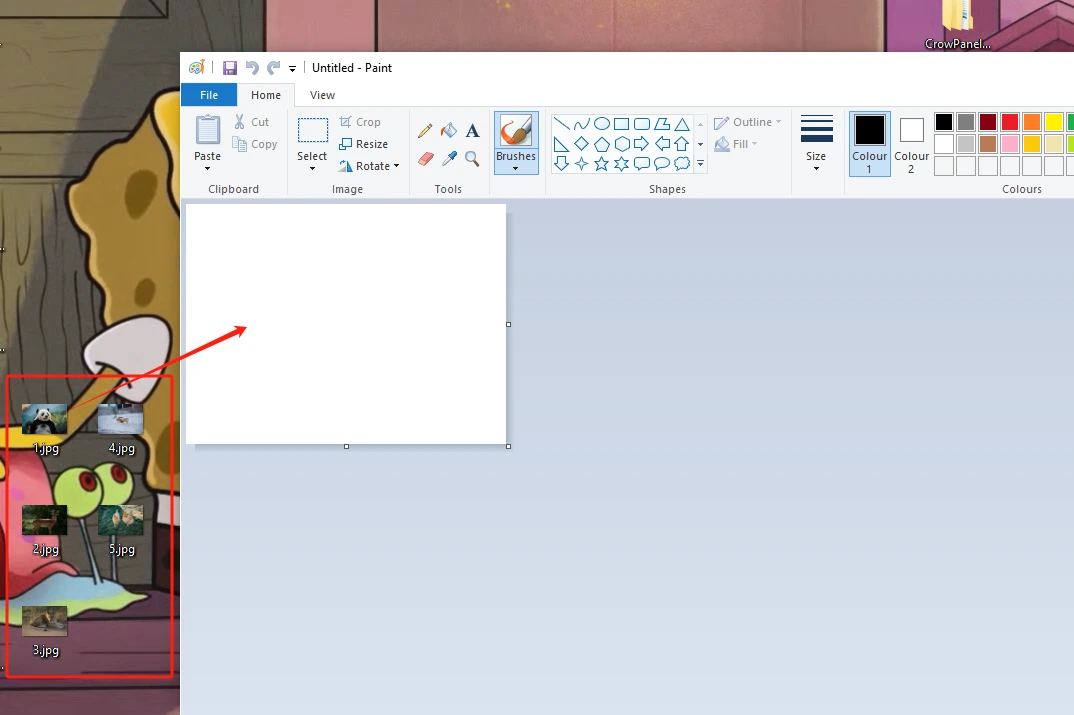
Drag and drop the image into the "paint" tool to readjust the pixels of the image
(Images can be uploaded to the browser and selected according to everyone's preferences)
Adjust the pixel to 7.0-inch screen resolution: 800x480
(If you are using a different size, please set the correct resolution)
Can be referred to:There are resolutions of different sizes as references above. (Second point)
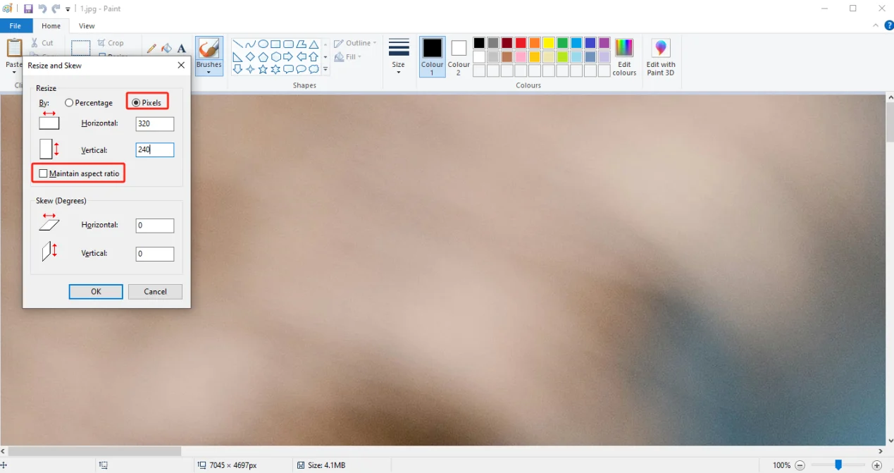
Click confirm
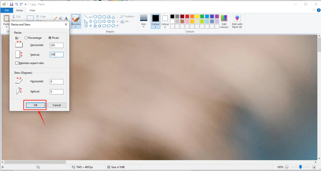
Adjust the resolution of the image as shown in the picture
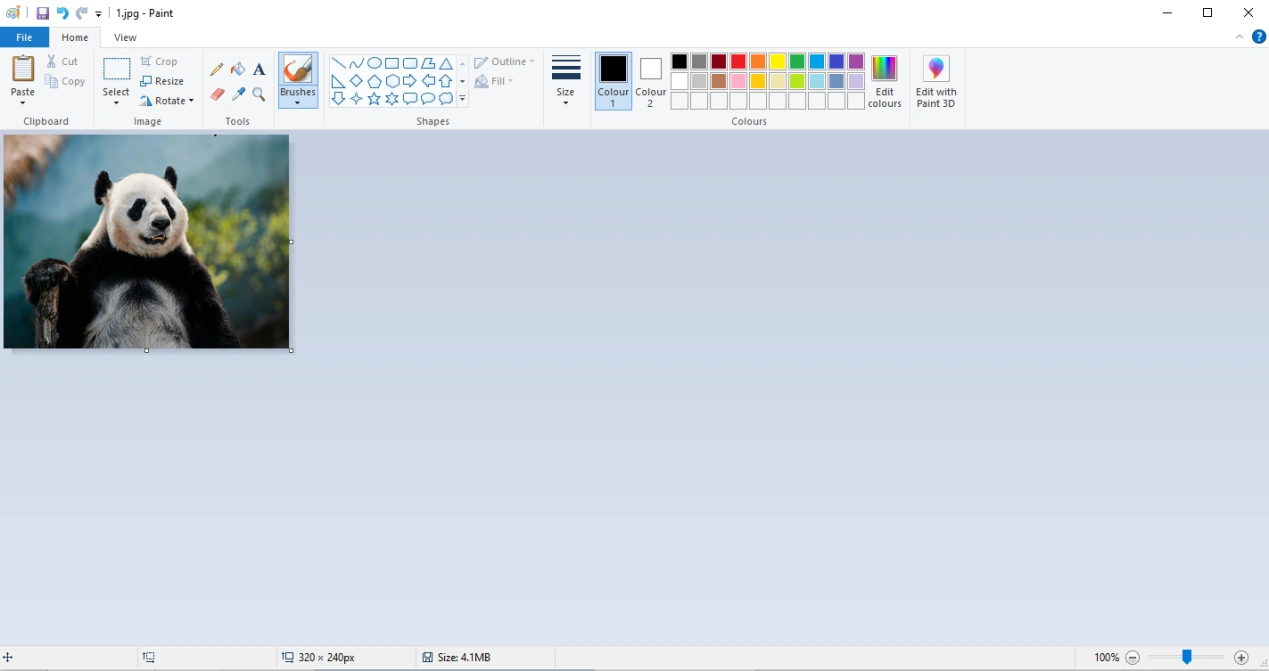
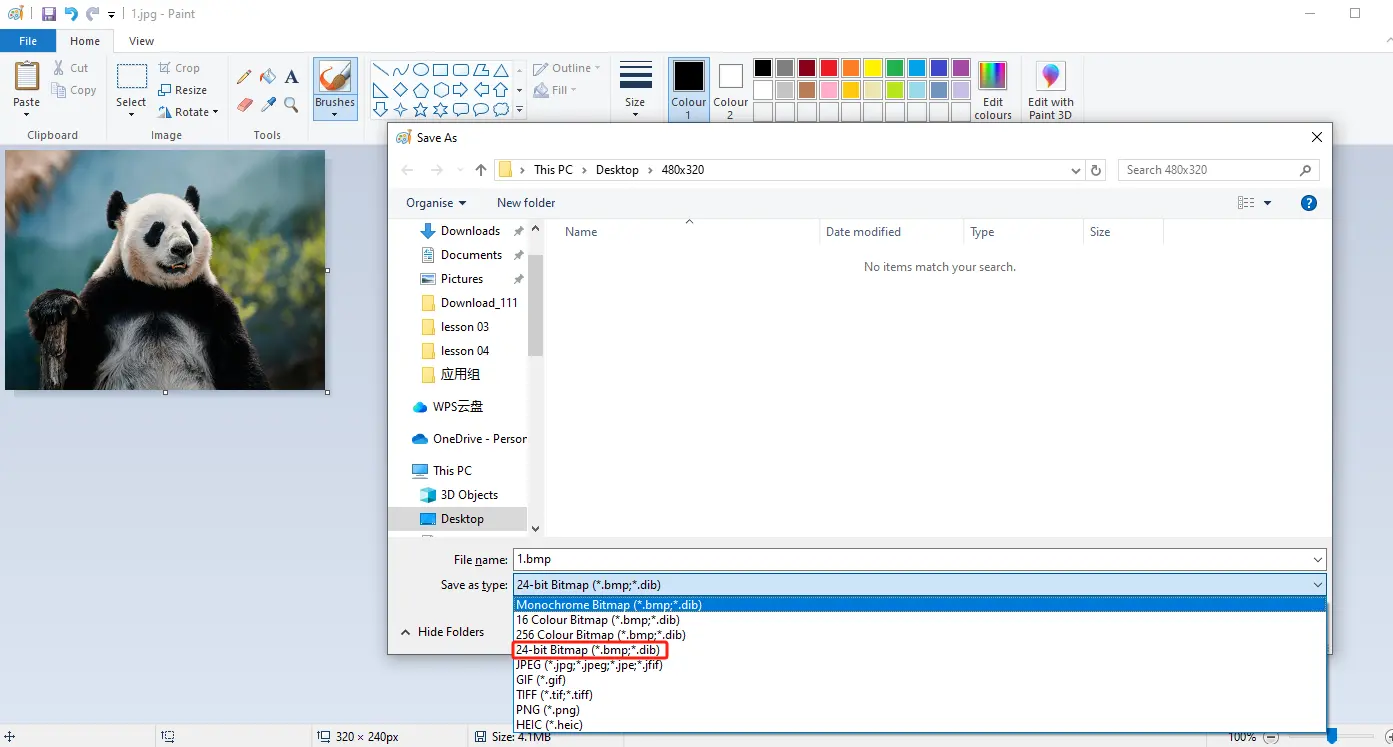
Save to a folder for easy use (folder path can be customized)
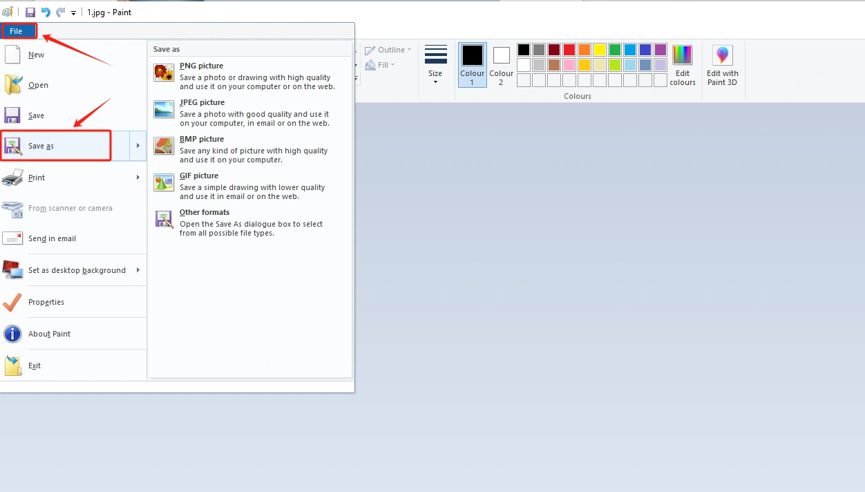
Save in BMP format (must have a 24 bit image depth)
Insert the SD card into the card reader

Open the SD drive, copy the modified image to the SD drive and save it
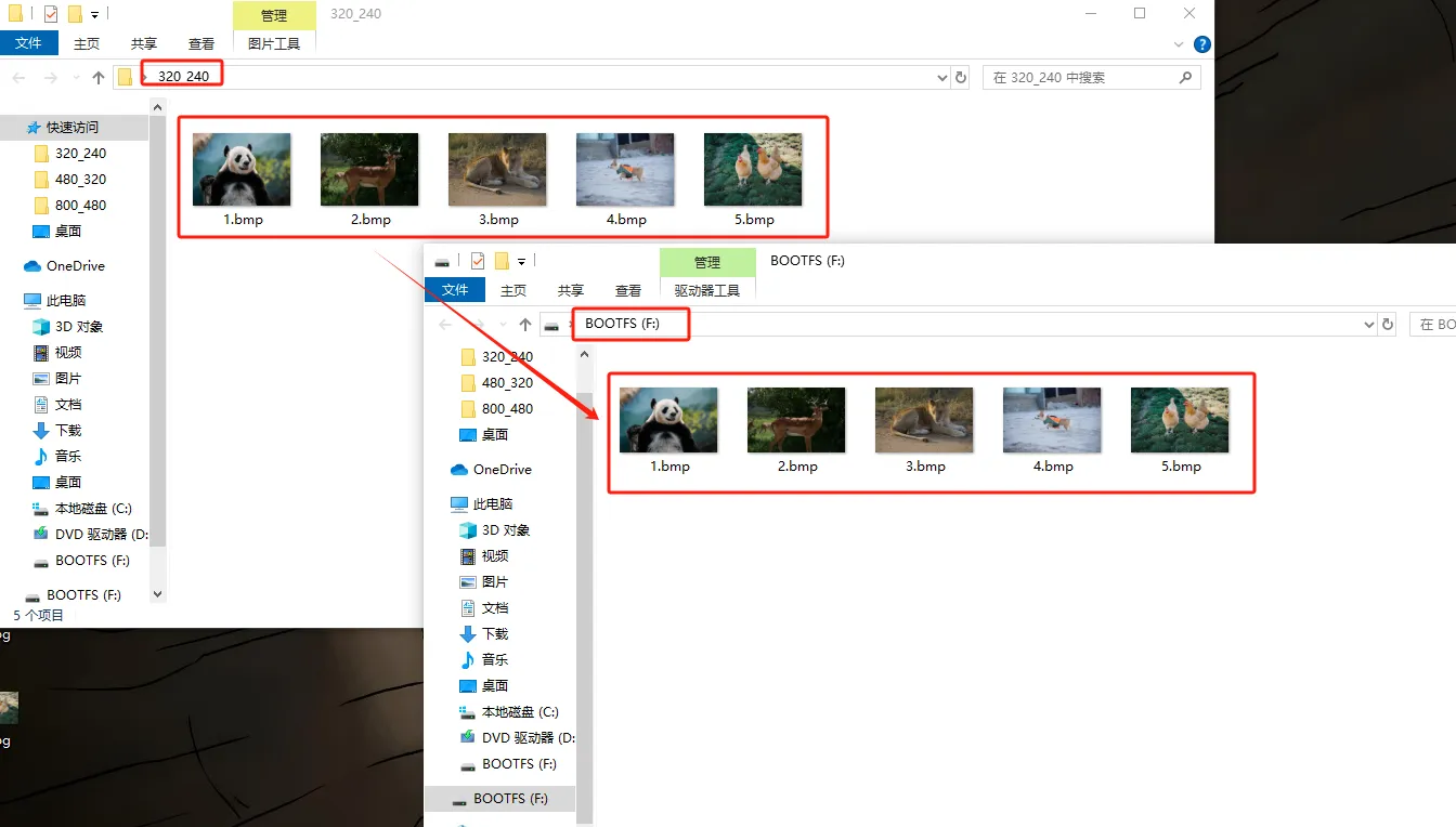
Exit the SD card and remove the SD card
3 Insert the SD card containing this saved image into your CrowPanel ESP32 Advance HMI
Insert the SD card into the TF card slot, provided that you have already placed the correct pictures inside it.

(2.4-inch, 2.8-inch, 3.5-inch products can be directly inserted for use)
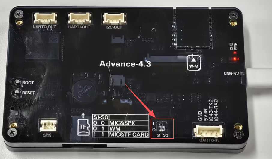
(After inserting the SD card, turn the function switch to 1 1 mode (TF Card mode) for 7.0-inch, 5.0-inch and 4.3-inch.)
4 Open the code we provide
Code download link:
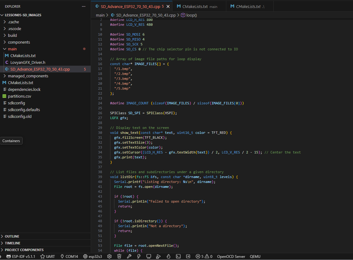
Download it to the Desktop and Open it with VS Code
5 Configure the runtime environment and burn code
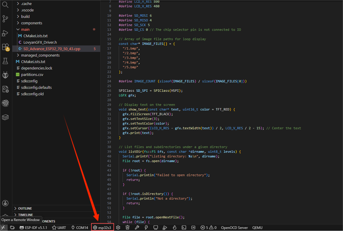
After Connecting the Device, Select the Serial Port

Set the Main Control Chip to: ESP32-S3
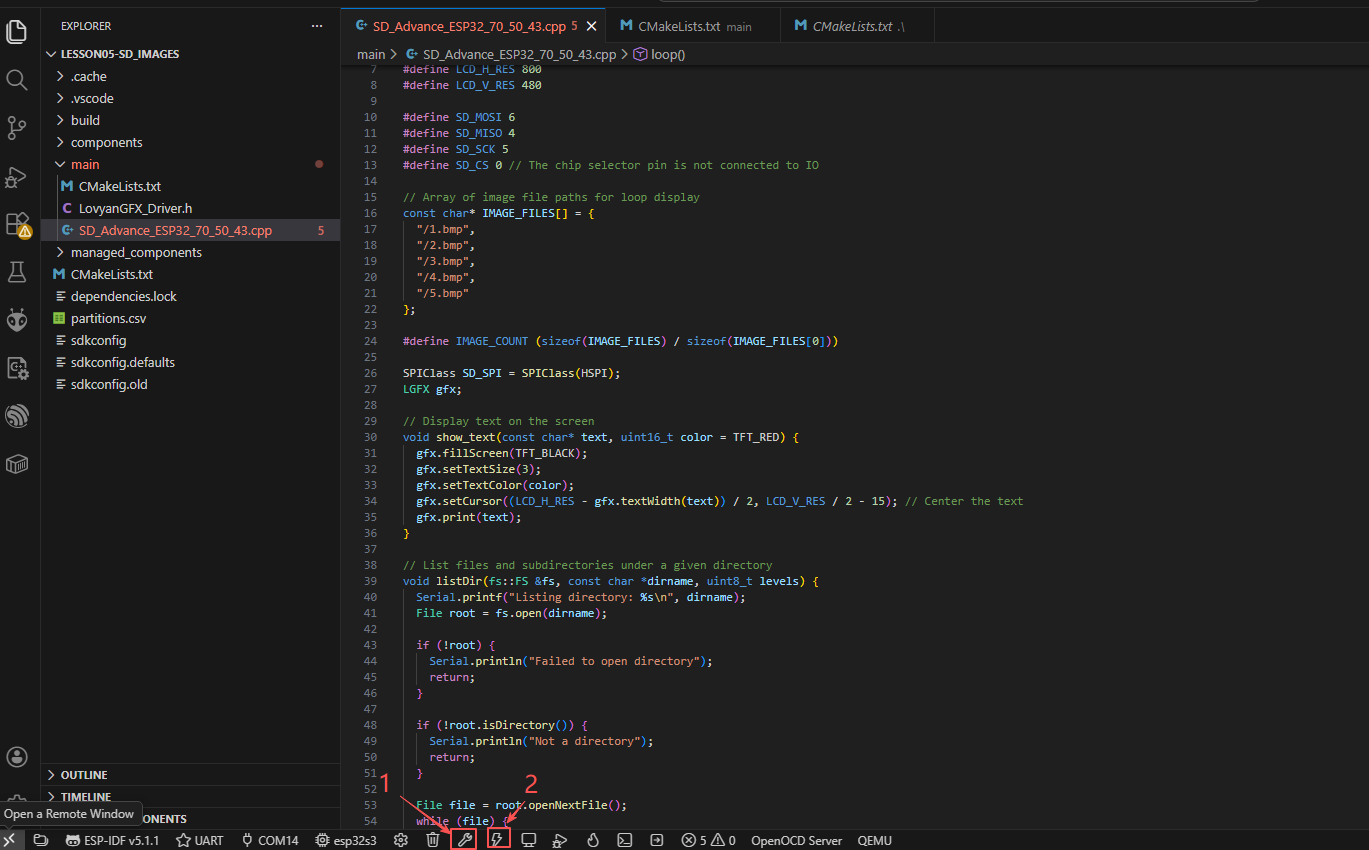
Click "Build Project". Once the compilation is complete, click "Flash Device".
6 Phenomenon display
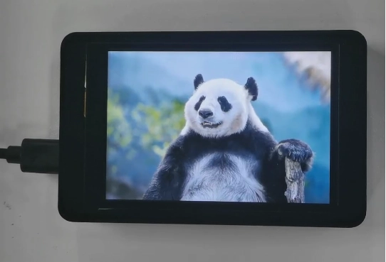

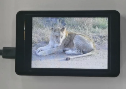
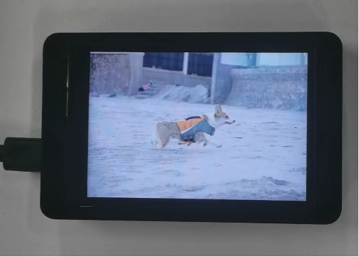
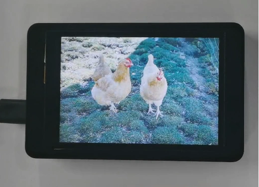
The five photos I saved on the SD card will be displayed in a loop.
Version 1.2 Key Points.
Kind Reminder:
You are currently viewing the 7-inch product of CrowPanel Advance HMI, and the version here is V1.2.
(The following precautions are also applicable to the 5.0-inch V1.1 version.)
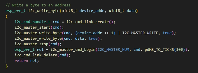
In terms of hardware, we use a microcontroller (STC8H1K28) to control the screen backlight and the mute function of the speaker.
(However, there are other function interfaces that need to be written in the specific code, and you can refer to the complete code provided later.)
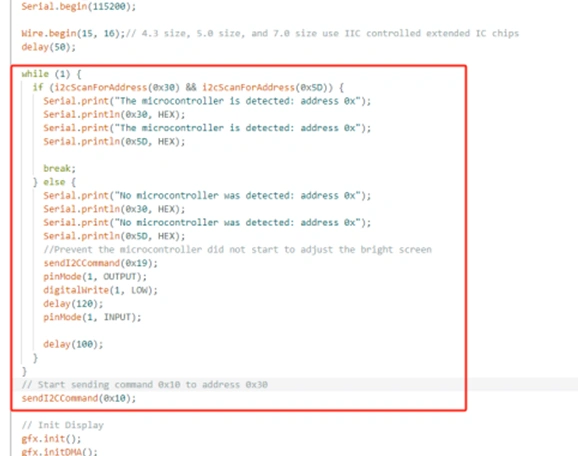
Explanation:
-
0x30 is the I2C address of the microcontroller (STC8H1K28).
-
0x5D is the I2C address of the touch IC (GT911).
-
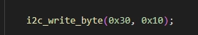
sendI2CCommand(0x10) means sending the 0x10 command to the microcontroller (0x30) to instruct the microcontroller to set the screen brightness to maximum.
(For 0x10 mentioned above, you can replace it with the following values:
-
0x05: Turn off the screen
-
0x06 to 0x10: The screen brightness will gradually increase to the maximum)
To set a different brightness level, you must first send 0x10 to turn on the screen, and then send another value to adjust the brightness.
Additional notes:
For the function interface sendI2CCommand(0x10), if 0x10 is replaced with the following values, the controlled functions will be different:
-
sendI2CCommand(0x15): It means sending the 0x15 command to the microcontroller (0x30) to instruct the activation of the buzzer.
-
sendI2CCommand(0x16): It means sending the 0x16 command to the microcontroller (0x30) to instruct the buzzer to be turned off.
-
sendI2CCommand(0x17): It means sending the 0x17 command to the microcontroller (0x30) to instruct the speaker to turn on.
-
sendI2CCommand(0x18): It means sending the 0x18 command to the microcontroller (0x30) to instruct the speaker to turn off.
By writing the instruction 0x10 to the address 0x30 of the microcontroller, it is used to control the microcontroller.