CrowPanel ESP32 7.0-inch with ESP-IDF
Requirements for the relevant version of the routine
IDF Version V5.5.4 Ivgl: 8.3.11
Overview
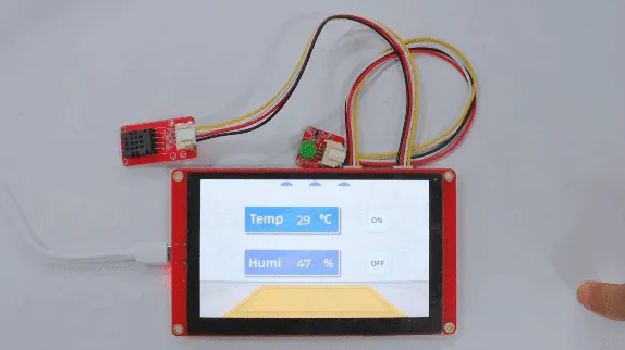
The example tutorial is an environmental monitoring project, demonstrate how to create a UI and use a DHT20 sensor to obtain the environment temperature and humidity and display it on the screen; and how to control the LED on and off by the buttons on the screen.
In this tutorial, we will show you how to design the UI with SquareLine Studio, and show you how to upload the code with ESP-IDF.

Hardware Preparation
| CrowPanel ESP32 7.0'' HMI | Crowtail-DHT20 | Crowtail-LED | Dupont-wire |
|---|---|---|---|
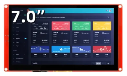 | 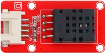 | 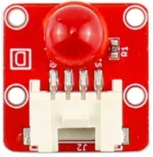 | 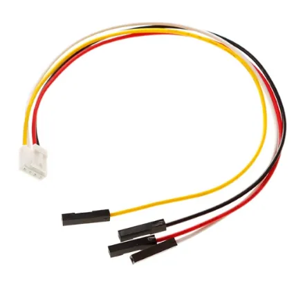 |
 |  | | |
Design UI file with SquareLine Studio
Please click the card below to learn how to download the SquareLine Studio, and how to export the demo UI file.

Design UI file with SquareLine Studio
Let's start learning how to create our own UI after getting an initial understanding of SquareLine Studio.
-
Open the SquareLine Studio and create a project.
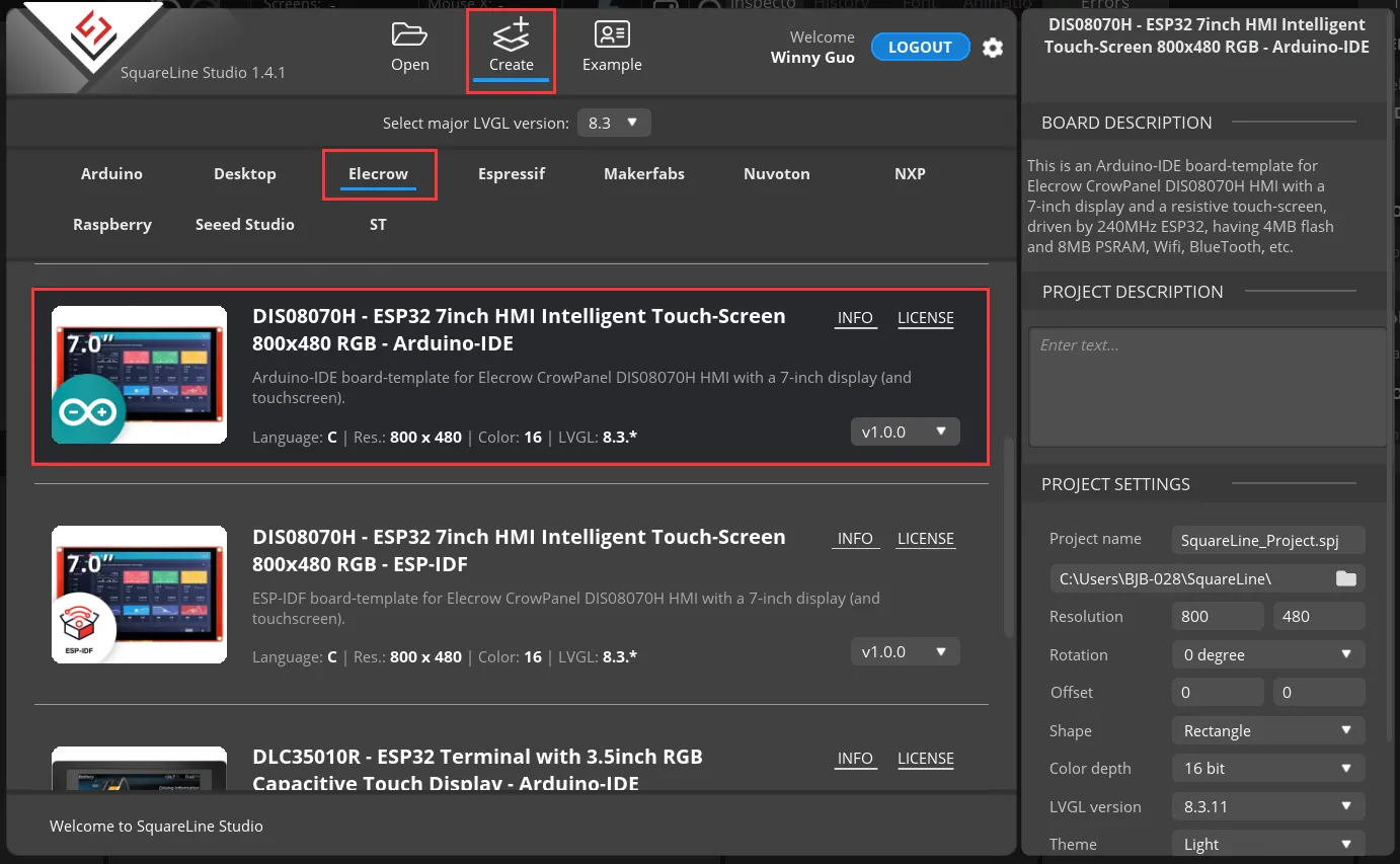
After using SLS to generate UI code, we then use different graphics libraries according to different hardware and modify the corresponding code to display the content you design.
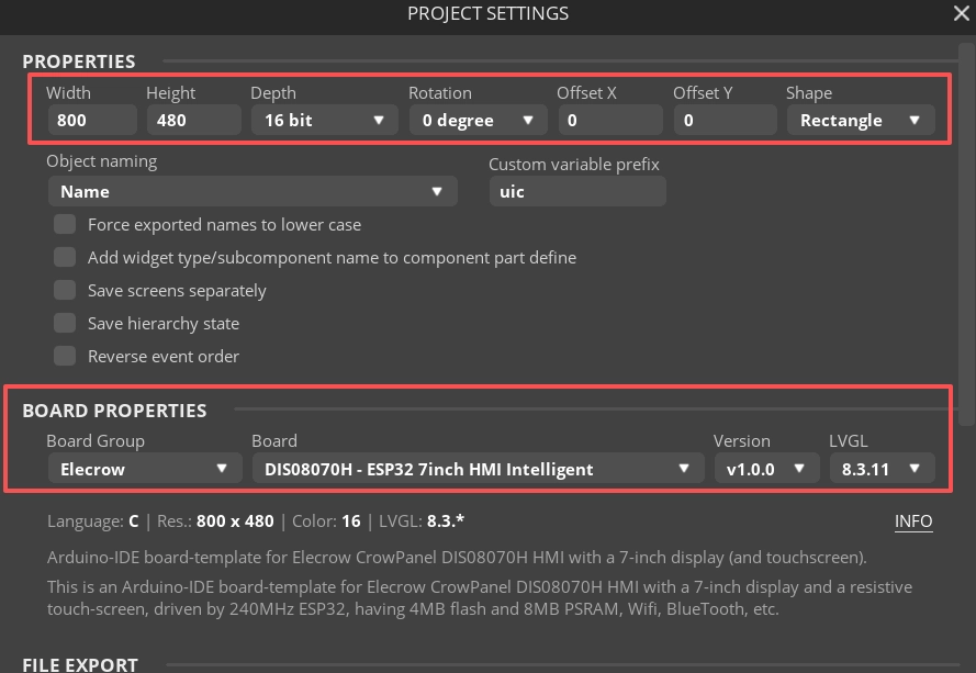
Set the name of the project, set the screen resolution to 800*480, set the color depth to 16bit, and keep other default settings. After setting, click CREATE to create the project.
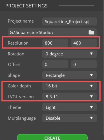
- 16-bit color depth: can represent 65,536 colors through RGB 5:6:5 sub-pixel representation, that is, each RGB channel occupies 5 bits and 1 bit (a total of 16 bits) to represent colors.
-
After creation, enter the following interface with a blank background.
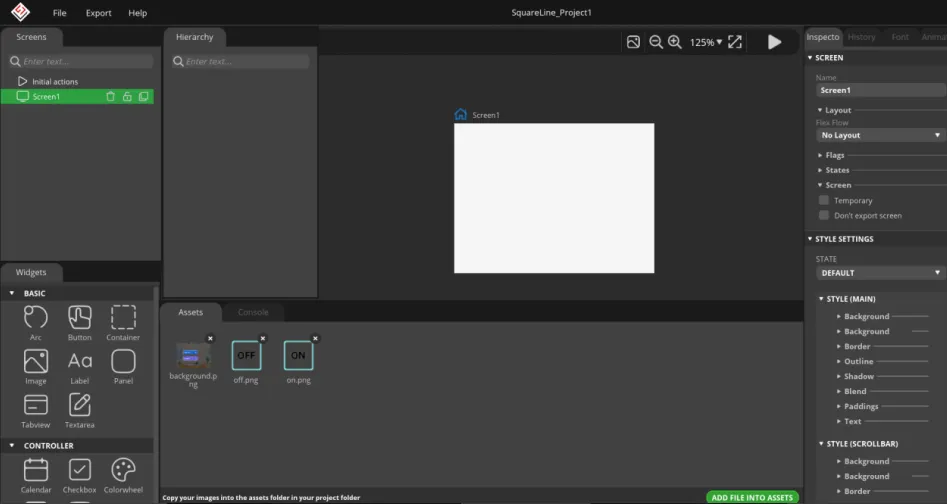
-
In the "Assets" area, click "ADD FILE TO ASSETS" to add custom images or icons.
Please click
 to download the custom images used in this tutorial.
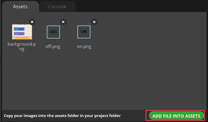
Note:
Images only support webp format. The pixels of the image need to be smaller than the pixel size of the screen used in your project. The size of each image should not exceed 100k, preferably within 30k, to provide a smooth display effect.
-
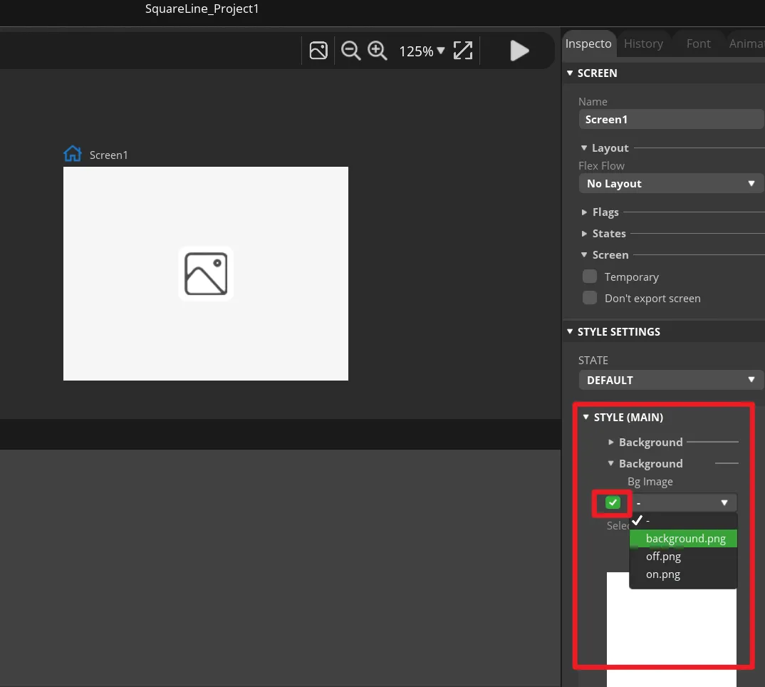
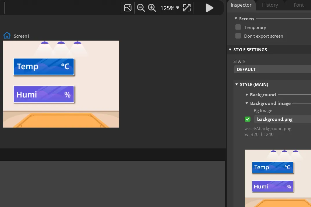
Add background.
Find "Inspector"->"STYLE SETTING", click to expand "STYLE(MAIN)", then click the 2nd "Background". Check the "Bg Image" and select the background image.
-
Add Label widget to display temperature and humidity.
Click "Label" in the "Widgets" area, and "Label1" will be added to the current Screen.
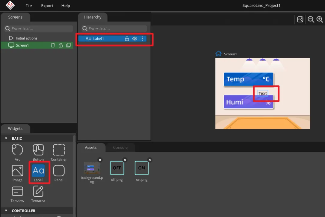
The position and size of the label can be adjusted by dragging the mouse. You can also directly enter numbers in the Inspector→LABEL→Transform to adjust.
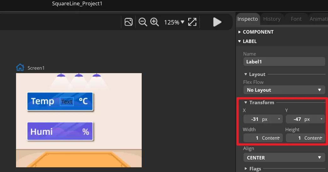
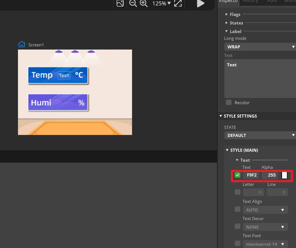
You can set the font colour and other attributes in STYLE SETTING→STYLE(MAIN).
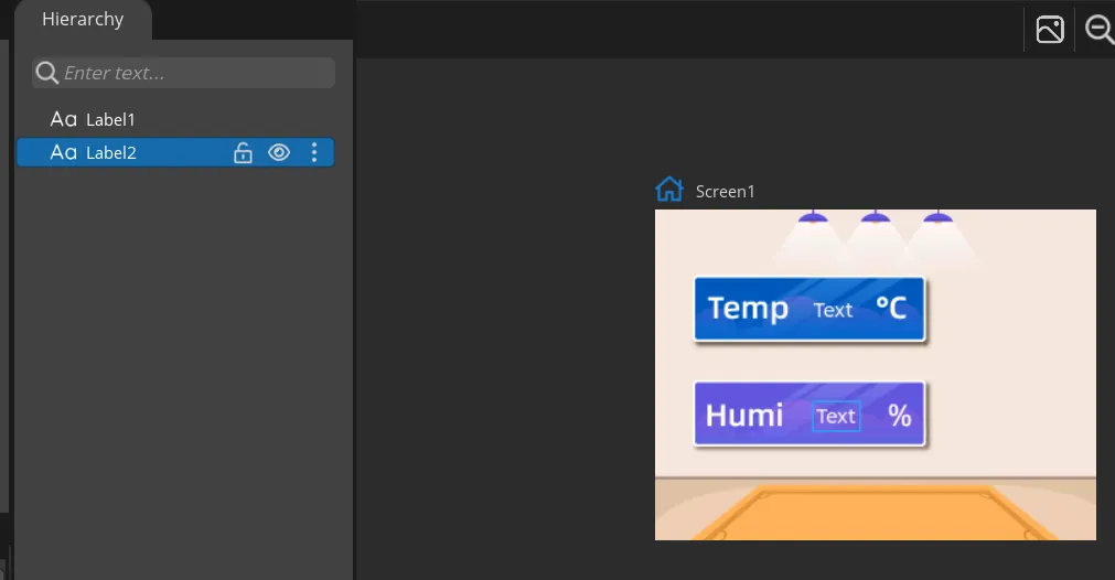
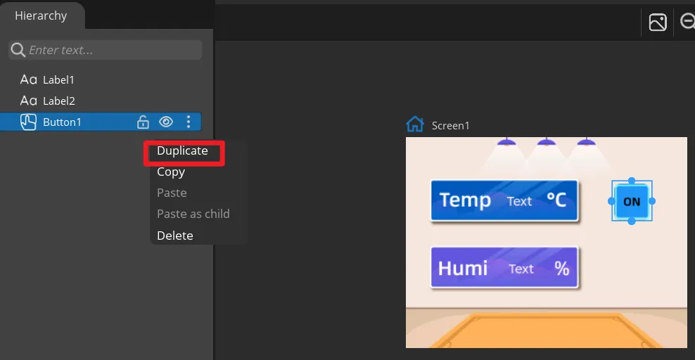
Add a Label2 to display the humidity value in the same way. You can also directly right-click the Label1 to duplicate it.
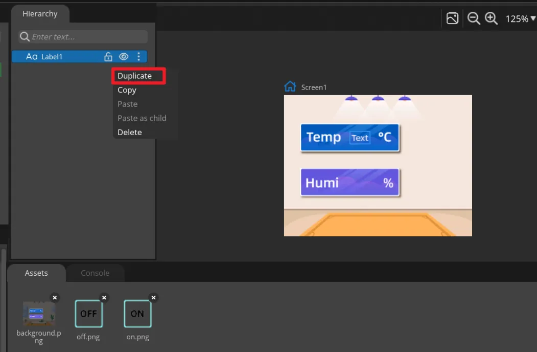
Then set different positions for the Label2.
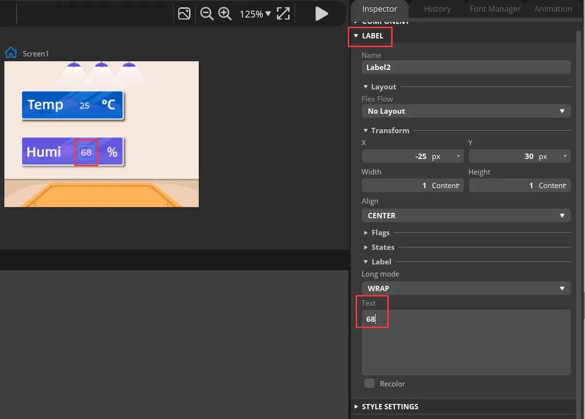
Modify the text content to display a default value.
-
Add Button widget to control the LED.
Click "Button" in the "Widgets" area, and "Button1" will be added to the current Screen.
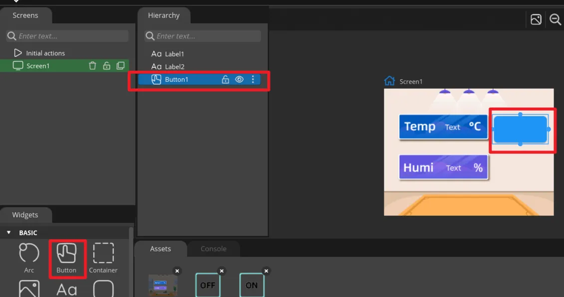
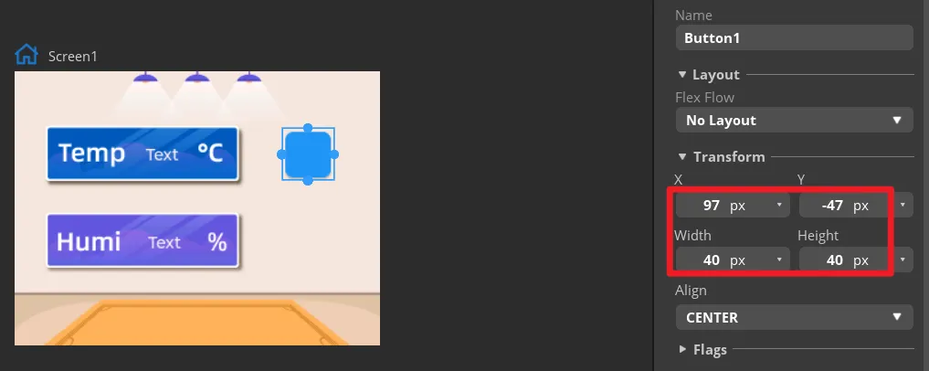
The position and size of the label can be adjusted by dragging the mouse. You can also directly enter numbers in the Inspector→BUTTON→Transform to adjust.
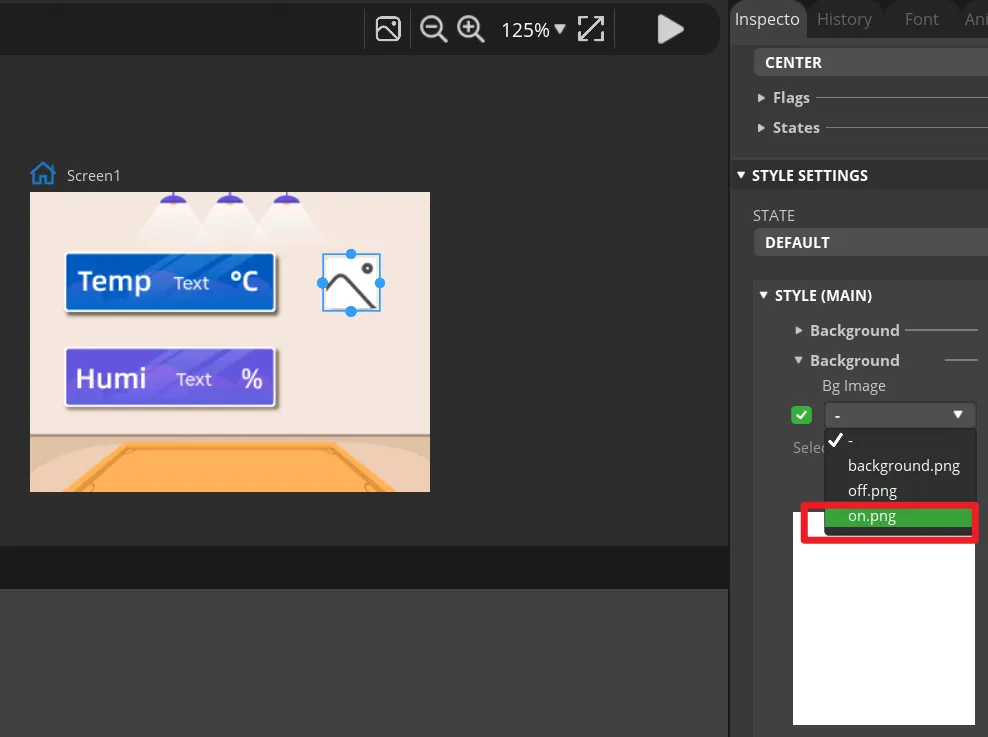
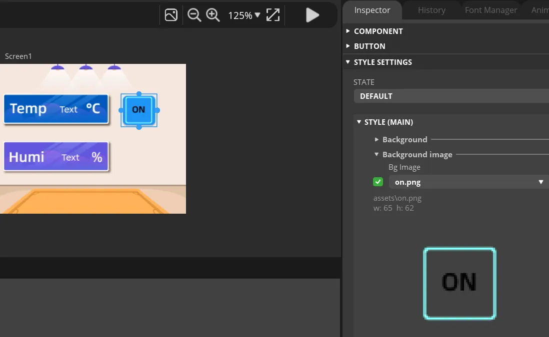
Add an identification symbol to the button. The button in this tutorial controls the LED switch, so you only need to mark the button "on" and "off". You can add LABEL widgets or add a background images to the button. This tutorial will demonstrate how to add a background image to a button.
Click the Button1, then find Inspector->STYLE SETTINGS ->STYLE(MAIN) ->Background, and select the image.
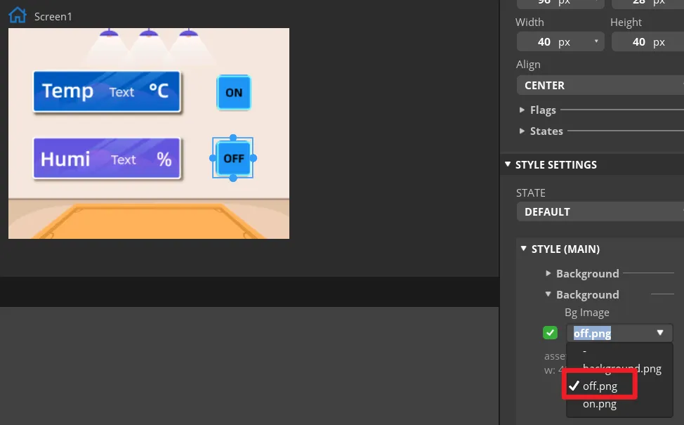
In the same way, duplicate a Button widget. And drag it to the corresponding position to modify different background image.
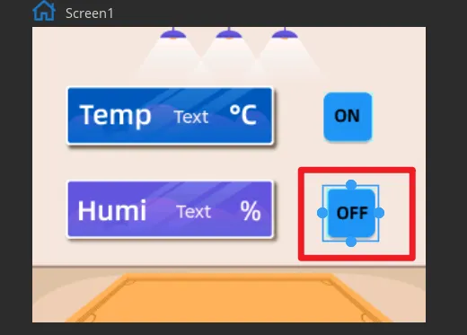
Set the status of the button to identify different states.
In "Inspector"->"STYLE SETTINGS"->"STATE", set display white background color by DEFAULT and red when on the PRESSED state.
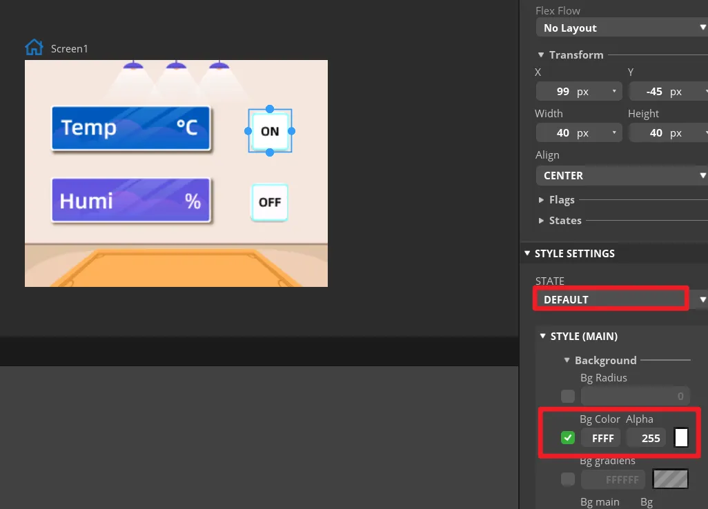
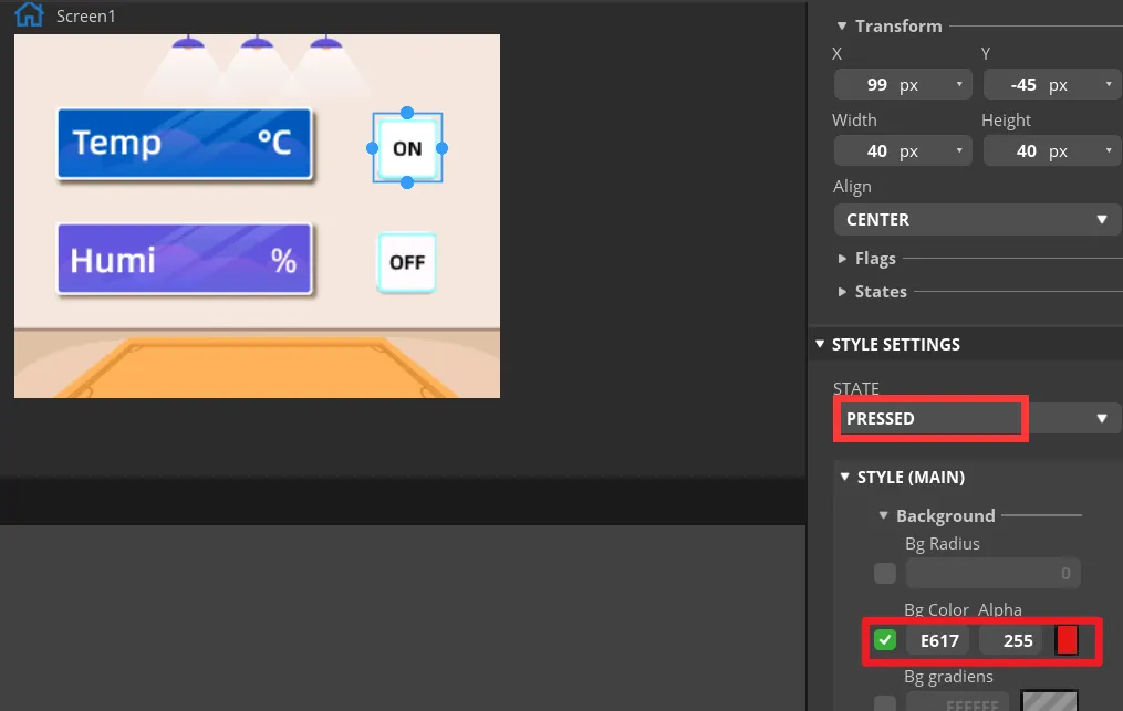
Make the same settings for the "OFF" button.
-
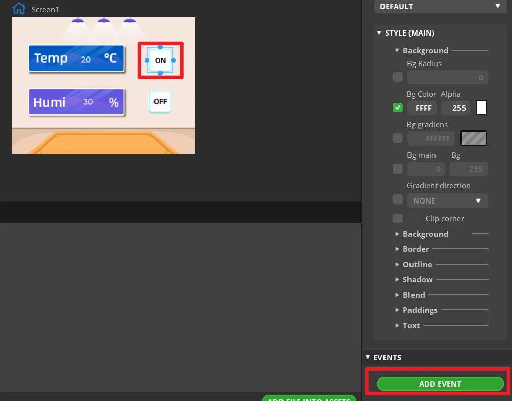
Add events to buttons.
Note: Because the button controls the on and off of the LED, we can add any event here to generate the code framework for the button event when exporting the UI file. We will modify the code of the button event to control the LED latter.
Select the button and click "ADD EVENT".
Select "clicked" as the trigger condition, select a trigger event in "Action". It will be modified in the generated program to achieve the LED control function.
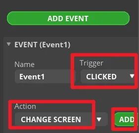
Complete the event. Here I choose to change the screen, and the screen to be switched is Screen1.
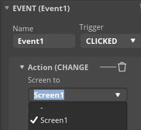
Add event to Button2 (OFF) in the same way.
-
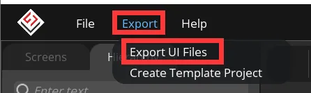
Export UI files.
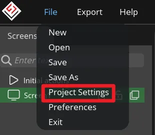
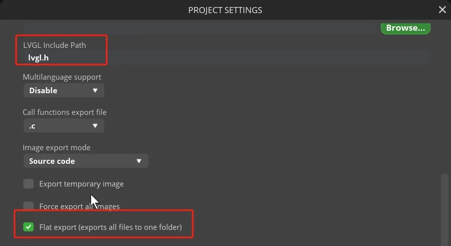
Click "File" -> "Project Settings" and make settings for the exported file.
Set the export path of the file (set the path according to your own file).
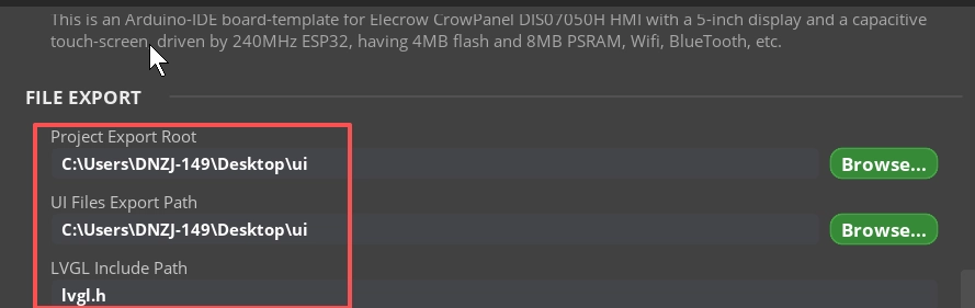
Fill in lvgl.h in LVGL Include Path. Check "Flat export(exports all files to one folder )".
Then click "APPLY CHANGES".
Tips: After selecting the flat export, the output files will be in the same folder, so that the output code does not need to modify the path in the program. If not, the output files will be classified and placed in different folders. The compiler may not be able to recognize different paths, which will cause some trouble. In this case, the user needs to modify it manually, so it is recommended to select all files to be output to the same folder.
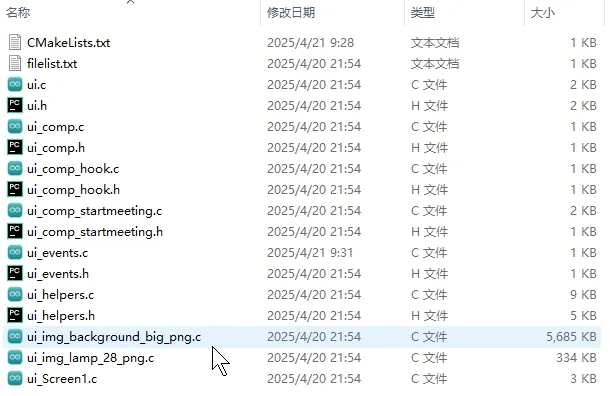
Export UI files. The exported files will be in the path we set earlier.
You can click
to download the export UI files we provided.
Build the Project with ESP-IDF
Get Started with ESP-IDF
Please click the card below to learn how to install ESP-IDF. Create a blank project according to the "Get Started with ESP-IDF".

You can click to download the complete project we provided. This project can be used directly. You can also create the project by following the tutorial.
Library introduction
In this project, we will use the following libraries:
#include <lvgl.h>
#include <DHT20.h>
#include <SPI.h>
#include <Arduino_GFX_Library.h>
#include <Arduino.h>
#include "ui.h"
#include <lvgl.h>: Library for UI interaction#include <DHT20.h>: The library of temperature and humidity sensors#include <SPI.h>: Screen driven library.#include <Arduino.h>: This is the core Arduino header file. It must be included when using the Arduino framework.#include <Arduino_GFX_Library.h>: This library handles the initialization and configuration of the display, including resolution, driver settings, and interface pins.#include "ui.h": is a custom header file that contain UI-related functions or definitions.
Code Explanation
Basic Definition
- Set the screen cache
Arduino_ESP32RGBPanel *bus = new Arduino_ESP32RGBPanel(
    41 /* DE */, 40 /* VSYNC */, 39 /* HSYNC */, 0 /* PCLK */,
    // R0~R4
    14 /* R0 */, 21 /* R1 */, 47 /* R2 */, 48 /* R3 */, 45 /* R4 */,
    // G0~G5
    9 /* G0 */, 46 /* G1 */, 3 /* G2 */, 8 /* G3 */, 16 /* G4 */, 1 /* G5 */,
    // B0~B4
    15 /* B0 */, 7 /* B1 */, 6 /* B2 */, 5 /* B3 */, 4 /* B4 */,
    0 /* hsync_polarity */, 40 /* hsync_front_porch */, 48 /* hsync_pulse_width */, 40 /* hsync_back_porch */,
    0 /* vsync_polarity */, 1 /* vsync_front_porch */, 31 /* vsync_pulse_width */, 13 /* vsync_back_porch */,
    1 /* pclk_active_neg */, 9000000 /* prefer_speed */, false /* useBigEndian */,
    0 /* de_idle_high */, 0 /* pclk_idle_high */, 480 /* bounce_buffer_size_px */
);

Arduino_RGB_Display *lcd = new Arduino_RGB_Display(
    800 /* width */, 480 /* height */, bus, 0 /* rotation */, false /* auto_flush */);
- Automatically refresh temperature and humidity data in real time.
void update_sensor_values() {
  int temperature = dht20.getTemperature();
  int humidity = dht20.getHumidity();

  if (ui_Label1) lv_label_set_text_fmt(ui_Label1, "%d", temperature);
  if (ui_Label2) lv_label_set_text_fmt(ui_Label2, "%d", humidity);

  Serial.print("Temp: ");
  Serial.print(temperature);
  Serial.println(" °C");

  Serial.print("Humi: ");
  Serial.print(humidity);
  Serial.println(" %");
}
- Touch reading function
void my_touchpad_read(lv_indev_drv_t *indev_driver, lv_indev_data_t *data)
{
    if (touch_has_signal())
    {
        if (touch_touched())
        {
            data->state = LV_INDEV_STATE_PR;
            data->point.x = touch_last_x;
            data->point.y = touch_last_y;
            Serial.printf("[LVGL] x=%d y=%d\n", touch_last_x, touch_last_y);
        }
        else if (touch_released())
        {
            data->state = LV_INDEV_STATE_REL;
        }
    }
    else
    {
        data->state = LV_INDEV_STATE_REL;
    }
    delay(15);
}
- Refresh function
void my_disp_flush(lv_disp_drv_t *disp, const lv_area_t *area, lv_color_t *color_p)
{
    uint32_t w = (area->x2 - area->x1 + 1);
    uint32_t h = (area->y2 - area->y1 + 1);

#if (LV_COLOR_16_SWAP != 0)
    lcd->draw16bitBeRGBBitmap(area->x1, area->y1, (uint16_t *)&color_p->full, w, h);
#else
    lcd->draw16bitRGBBitmap(area->x1, area->y1, (uint16_t *)&color_p->full, w, h);
#endif

    lv_disp_flush_ready(disp);
}
Setup Part
void setup()
{
    Serial.begin(115200);
    delay(100);
    Serial.println("setup() start");

    dht20.begin();

    Wire.begin(19, 20); // still needed for DHT20

    // Control pin 38 (matching Arduino version)
    pinMode(38, OUTPUT);
    digitalWrite(38, LOW);

    lv_init();

    Serial.println("Calling lcd->begin()...");
    bool ok = lcd->begin();
    Serial.printf("lcd->begin() returned: %d\r\n", ok);
    if (!ok) {
        Serial.println("lcd->begin() failed, halt");
        while (1) {
            delay(1000);
        }
    }

    // Test: fill screen with black (matching Arduino version)
    lcd->fillScreen(0x0000);
    delay(100);

    touch_init();
    delay(50);

    //pinMode(38, OUTPUT);
    //digitalWrite(38, LOW);

    screenWidth = lcd->width();
    screenHeight = lcd->height();

    // Use 1/10 of screen as draw buffer (recommended for LVGL 8.x)
    const size_t draw_buf_pixels = screenWidth * screenHeight / 10;
    lvgl_draw_buf = (lv_color_t *)heap_caps_malloc(draw_buf_pixels * sizeof(lv_color_t),
                                                   MALLOC_CAP_SPIRAM | MALLOC_CAP_8BIT);
    if (!lvgl_draw_buf) {
        Serial.println("draw buffer alloc failed");
        while (1) {
            delay(1000);
        }
    }
    lv_disp_draw_buf_init(&draw_buf, lvgl_draw_buf, NULL, draw_buf_pixels);

    lv_disp_drv_init(&disp_drv);
    disp_drv.hor_res = screenWidth;
    disp_drv.ver_res = screenHeight;
    disp_drv.flush_cb = my_disp_flush;
    disp_drv.draw_buf = &draw_buf;
    lv_disp_drv_register(&disp_drv);

    static lv_indev_drv_t indev_drv;
    lv_indev_drv_init(&indev_drv);
    indev_drv.type = LV_INDEV_TYPE_POINTER;
    indev_drv.read_cb = my_touchpad_read;
    lv_indev_drv_register(&indev_drv);

    ui_init();

    // Backlight control (matching new board Arduino version)
#ifdef TFT_BL
    ledcAttach(TFT_BL, 300, 8);
    ledcWrite(TFT_BL, 255);
#endif
    pinMode(TFT_BL, OUTPUT);
    digitalWrite(TFT_BL, LOW);
    delay(500);
    digitalWrite(TFT_BL, HIGH);

    Serial.println("Setup done");
}
Main Program Part
void loop()
{
    static uint32_t last_tick_ms = millis();

    uint32_t now = millis();
    lv_tick_inc(now - last_tick_ms);
    last_tick_ms = now;

    lv_timer_handler();
    delay(5);

    // Handle LED state changes from UI button events
    if (led != last_led_state) {
        last_led_state = led;
        // TODO: Change LED_PIN to match your actual LED connection
        const int LED_PIN = 38;
        pinMode(LED_PIN, OUTPUT);
        digitalWrite(LED_PIN, led ? HIGH : LOW);
        Serial.printf("LED state changed: %d\n", led);
    }

    static unsigned long last_update = 0;
    if (millis() - last_update > 2000) {
        update_sensor_values();
        last_update = millis();
    }
}
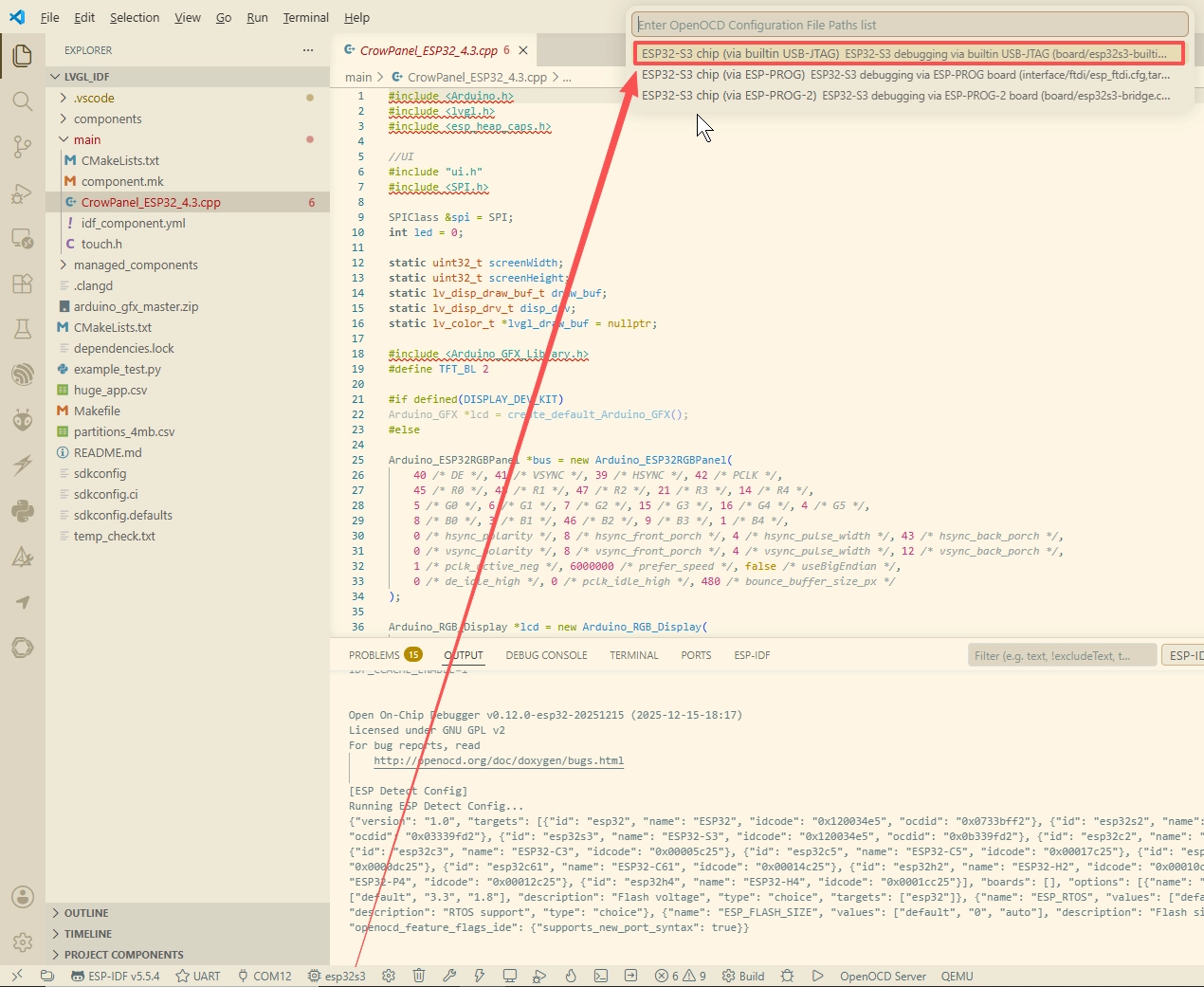
Setup board
Download the program
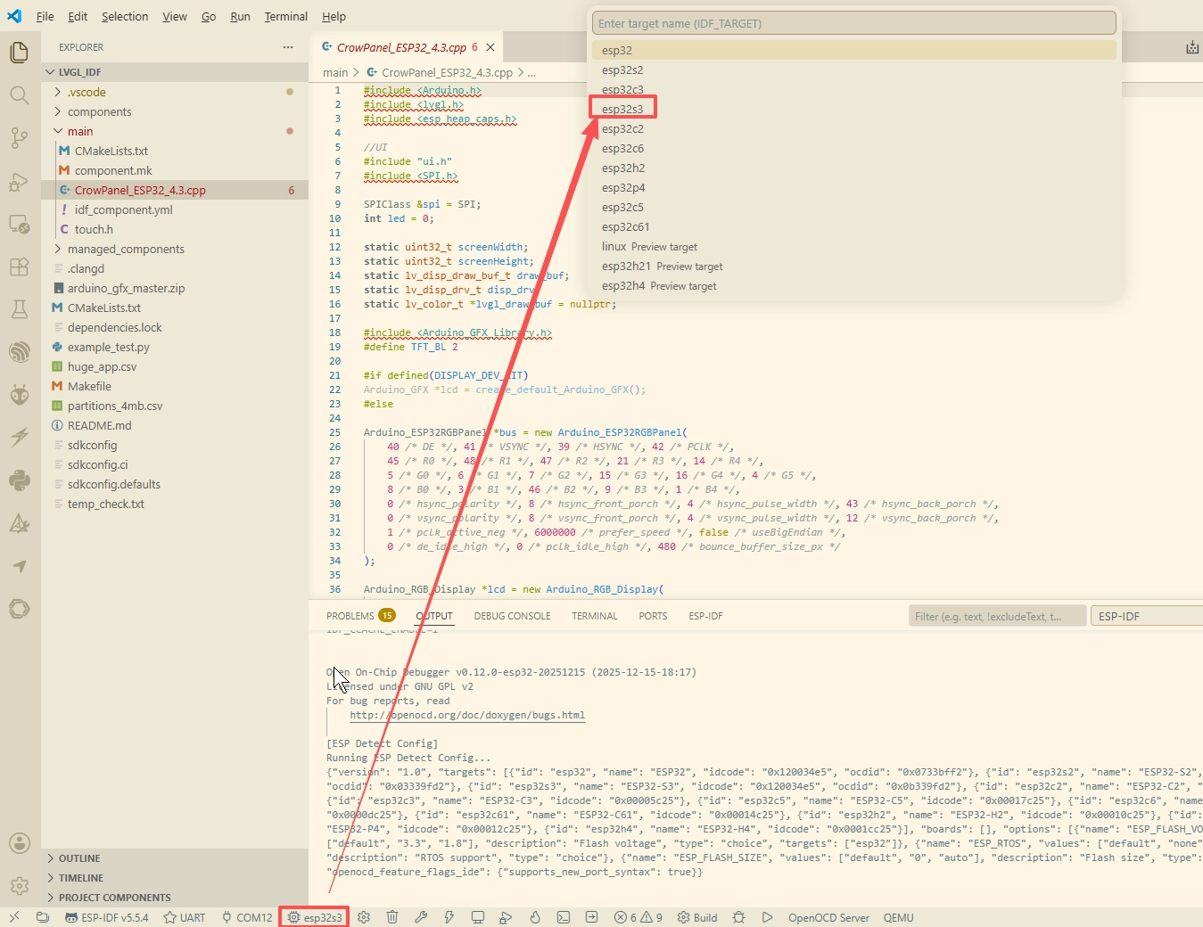
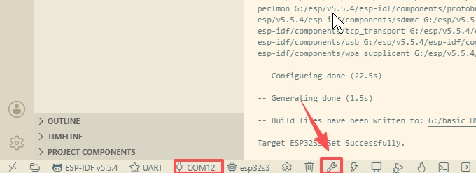
Connect the ESP32 Display to the PC and compile the program.
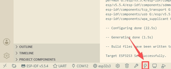
After confirming the serial port, select the UART mode.
After the program is successfully downloaded, connect the DHT20 sensor to the IIC port and the LED to GPIO_D (IO25), the temperature and humidity values will be displayed on the screen. Click the ON button on the screen and the LED will turn on. Click the OFF button and the LED will turn off.