Case 2:Multi-Channel Application Routine for Single-Channel Gateways and Nodes
Equipment: Lorawan gateway module
Gateway configuration
1.Initialise the gateway:
Long press the BOOT key for 3s to initialise the gateway, check the initialisation information on the gateway display. As shown in the picture.
2. Go to the web side to initialise the gateway configuration:
Connect the wifi of the gateway, enter 192.168.4.1 on the browser to enter the webpage; Configure the gateway networking method WIFI (you must enter the correct wifi account password); Press Gateway Default to get the default ID of the gateway, or enter the 16-digit ID by yourself (the ID needs to be the same as the TTN gateway ID); Enter the server address port; REGION set the gateway working band (US915 for example); set the gateway channel (CHANNEL) (915 band has 8 ranges of 0-7, the band should be the same as the node band) and the spreading factor (SF note: use LR1262 node 915 band set spreading factor is 10). As shown in the pictures.
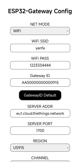
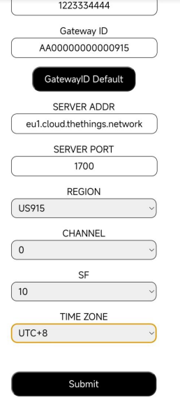
Generally, SF10 is used for long communication distance, and the channel selection is 0. Time zone setting, set the corresponding time zone can be set.
3. After confirming that there are no errors, click Submit to submit the configuration information, and the gateway will load the corresponding configuration
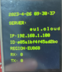
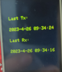
You can check the time when the last gateway sent and received data by switching to the next page.
TTN configuration
1. Add gateway (TTN address eu1.cloud.thethings.network, you need to register an account to access the console to add)

Enter the gateway ID, click Confirm, enter the gateway name, and select the operating band.
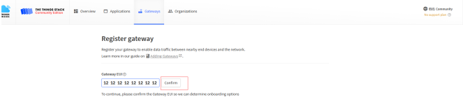
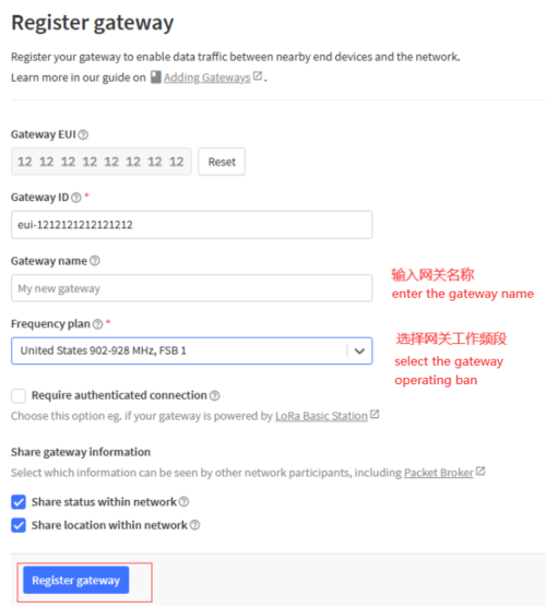
Note: Select the band "United States 902-928MHz FSB1" (select this band when testing LoRa nodes using the 915MHz band).
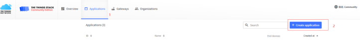
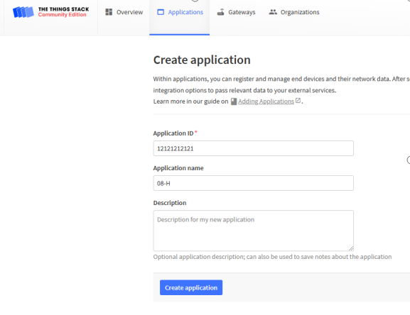
2. Add Node
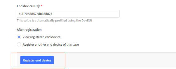
Enter the node ID, name, and description
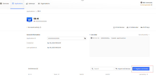
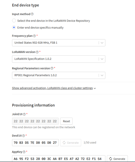
Configure the node parameters added by TTN to the node.
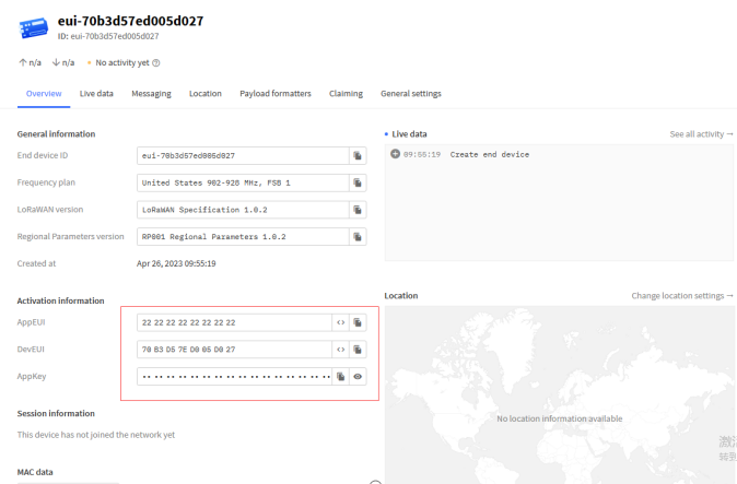
It must be confirmed that the LR1262 module has been burned with the factory firmware programme. Open the serial port tool and enter the network.
LR1262 Node
1. Open the serial port tool, serial port settings
1). Baud rate: 9600 2). Tick the serial port carriage return line feed
2. Node access multi-channel gateway configuration steps (send AT command)
1). Select the node for single channel/multi-channel mode mode: AT+ChannelMode=1 (1 for multi-channel)
2). Set the node into the network frequency band: AT + BAND = 8 (8 for 915 band)
3). Set the node entry triad (OTAA):
Set node DevEui: AT+DevEui=70B3D57ED005B7FF
Set node AppEui: AT+AppEui=000000000000000003
Set node AppKey: AT+AppKey=A8D7E5959F7746D902BF52BA2F899E3E
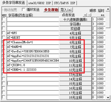
4). Setting the node to start netting: AT+JOIN=1,8 (parameter description: the first parameter is to select the netting mode, 0 is ABP mode, 1 is OTAA mode, the second parameter is the number of times of cyclic request for netting in OTAA mode (1-8), no cycle is needed in ABP mode)

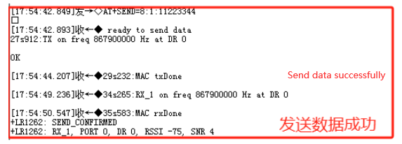
5). Start sending data: AT+SEND=1:1:223333 (parameter description: the last parameter is the data to be sent, and only an even number of data can be sent)