6.nRF2401 communication
Welcome to Lesson 6 of this series - nRF2401 Wireless Communication.
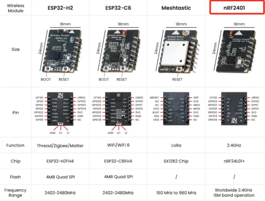
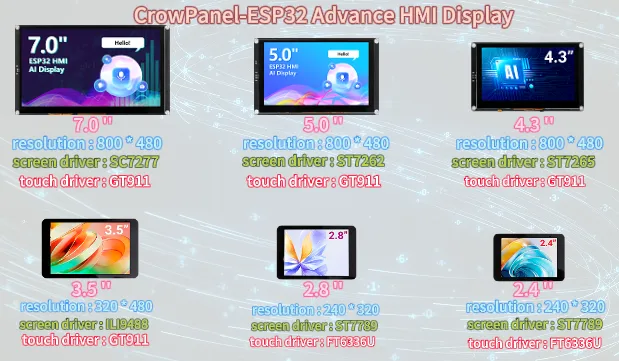
We provide a total of four wireless modules for you to use.
ESP32-H2 and ESP32-C6 are predominantly utilized for Zigbee and Wi-Fi communication. Meshtastic, on the other hand, is mainly employed for LoRa communication.
As for NRF2401, it is chiefly used for RF communication.
For specific details of each size, please visit our official website
In this lesson, we will teach you how to use our nRF2401 wireless module.
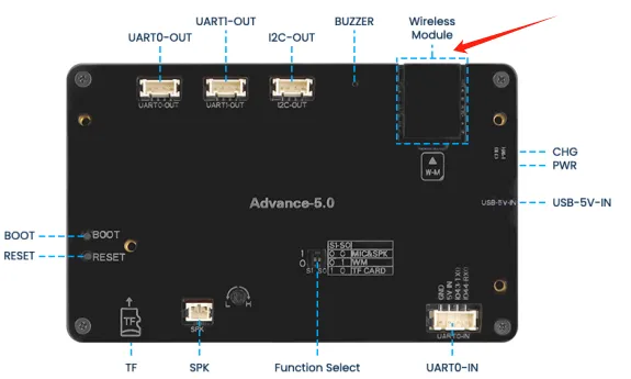
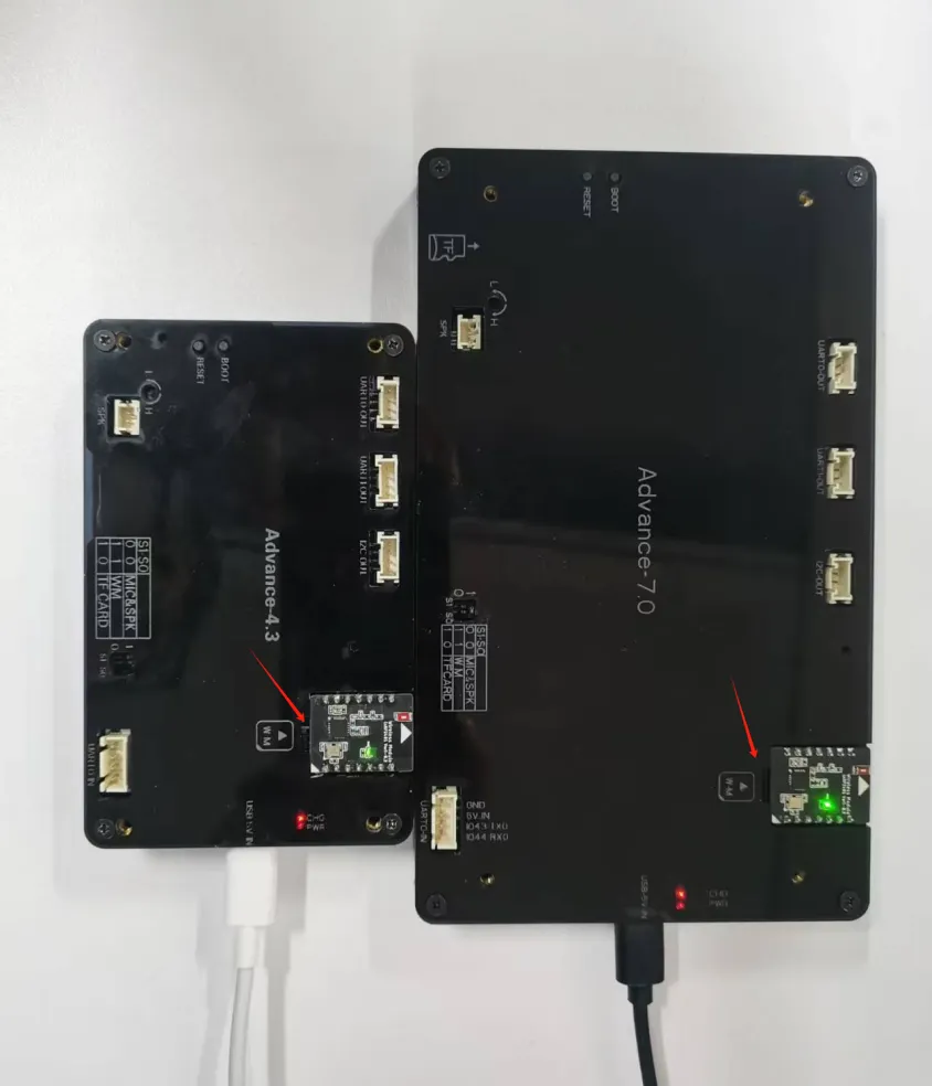
To use our nRF2401 wireless module, you need to prepare two CrowPanel ESP32 Advance HMI Displays of any size.

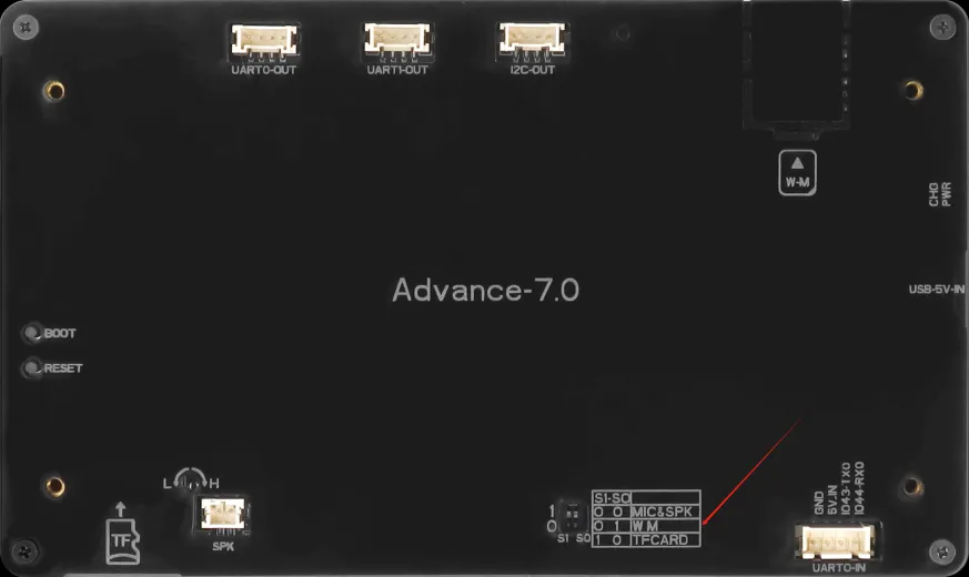
One of the nRF2401 wireless modules is inserted into the W-M wireless module slot to perform the sending task;
Another nRF2401 wireless module is inserted into the W-M wireless module slot to perform the receiving task.

1 Framework
Click the link below to download the code used in this lesson.
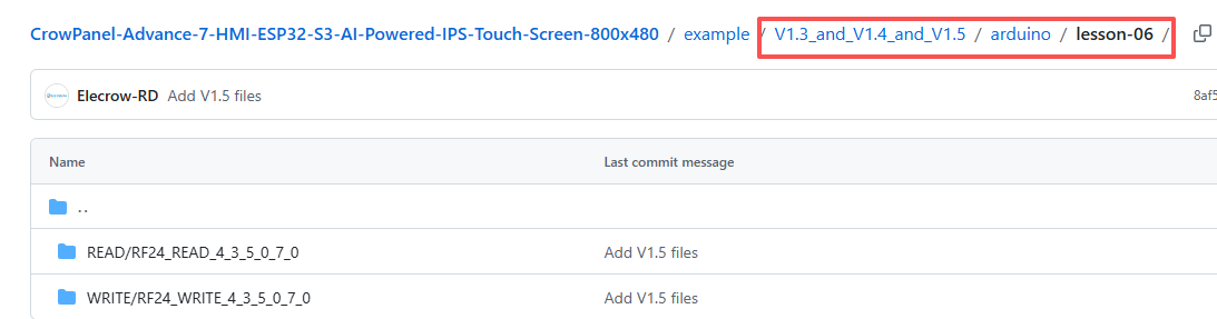
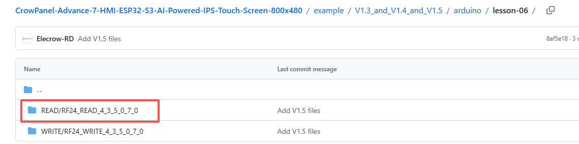
Divided into two folders:
The READ folder is the code responsible for receiving information for each CrowPanel ESP32 Advance HMI size;
The WRITE folder is the code responsible for sending information for each CrowPanel ESP32 Advance HMI size.
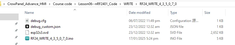
First, open the WRITE folder.
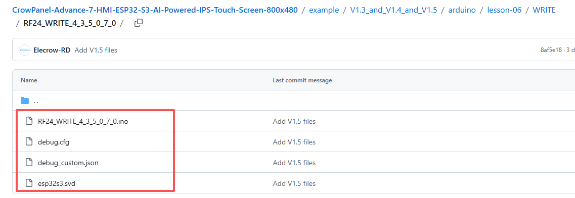
We use a size of 4.3 as a role for sending messages and a size of 7.0 as a role for receiving messages.
2 An nRF2401 is responsible for sending messages
Firstly, burn the "WRITE" function on the 4.3-inch product and open the corresponding code.
Initialize the pins SPI of the wireless module to enable it to work.
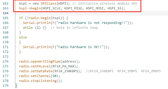
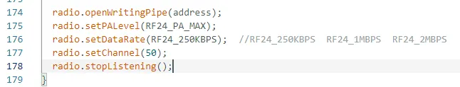
Set the relevant parameters of nRF2401 module
Store the message to be sent in the text variable, and call the radio. Write() function interface to send the text content.
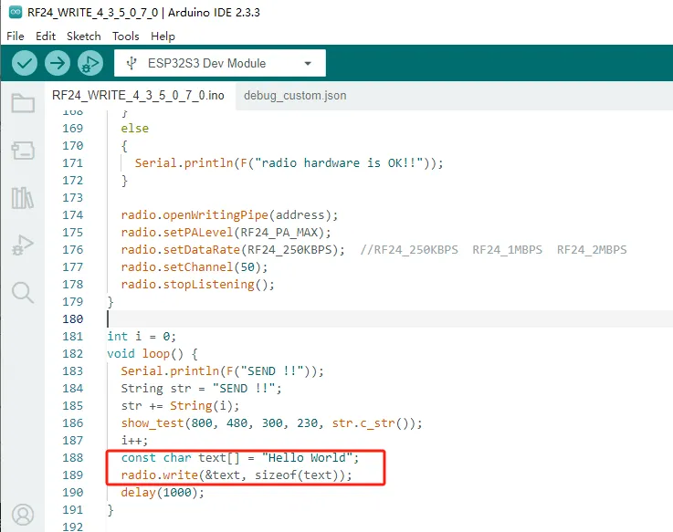
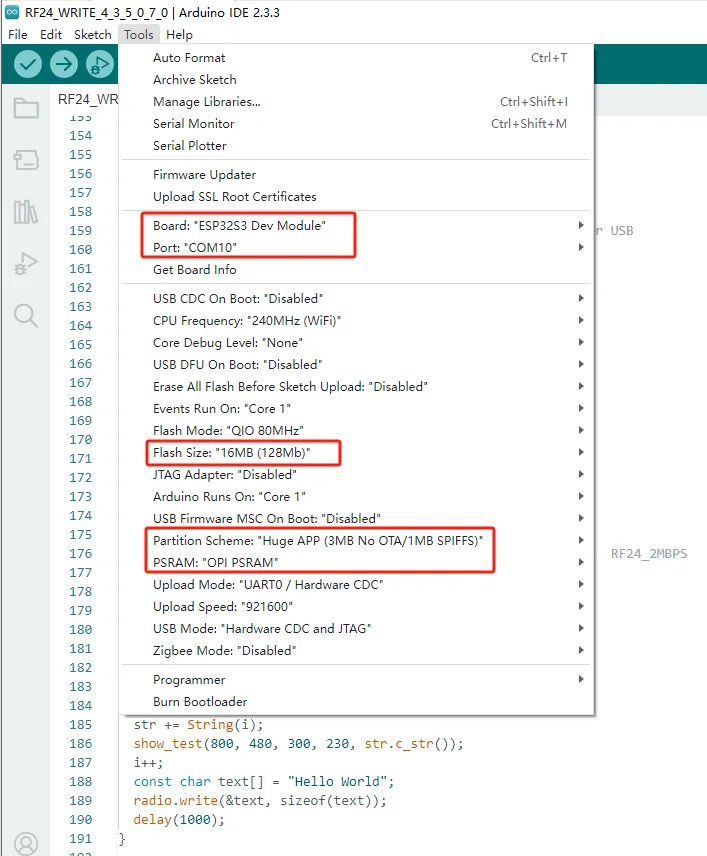
Set up the code running environment and upload the code

Be careful:
① During the process of programming the product, please do not insert the nRF2401 wireless module into the W-M slot.
Because the BOOT pin of the CrowPanel ESP32 Advance HMI needs to be kept low, but after inserting the nRF2401 wireless module into the W-M slot, the IRQ pin of the nRF2401 wireless module will default to pulling up the BOOT pin, which can cause burning failure.
So it is necessary to upload the code to the CrowPanel ESP32 Advance HMI before inserting the nRF2401 wireless module into the W-M slot for use.
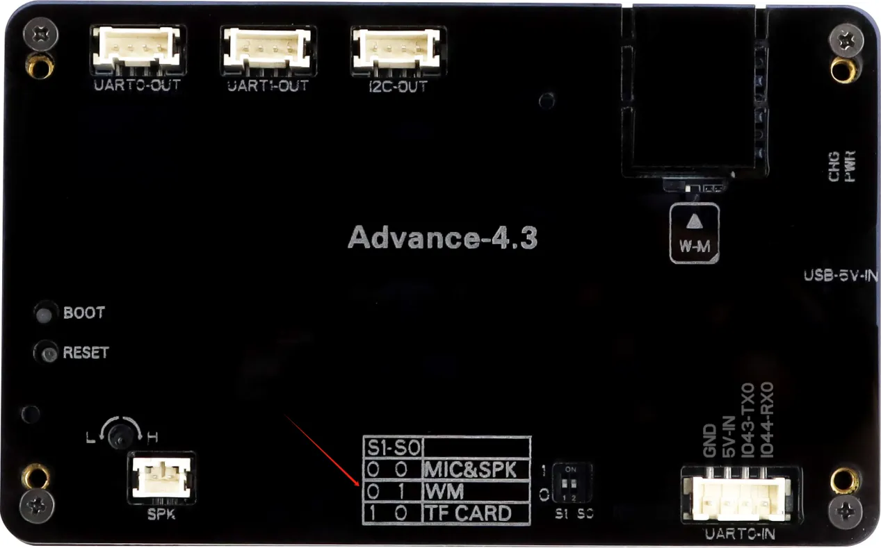
② When using 4.3 size, 5.0 size, and 7.0 size products, please remember to switch the mode to 0 1 wireless mode.
③ Before uploading the code, please remember to switch to using our library files. If you have forgotten, you can review the second lesson.
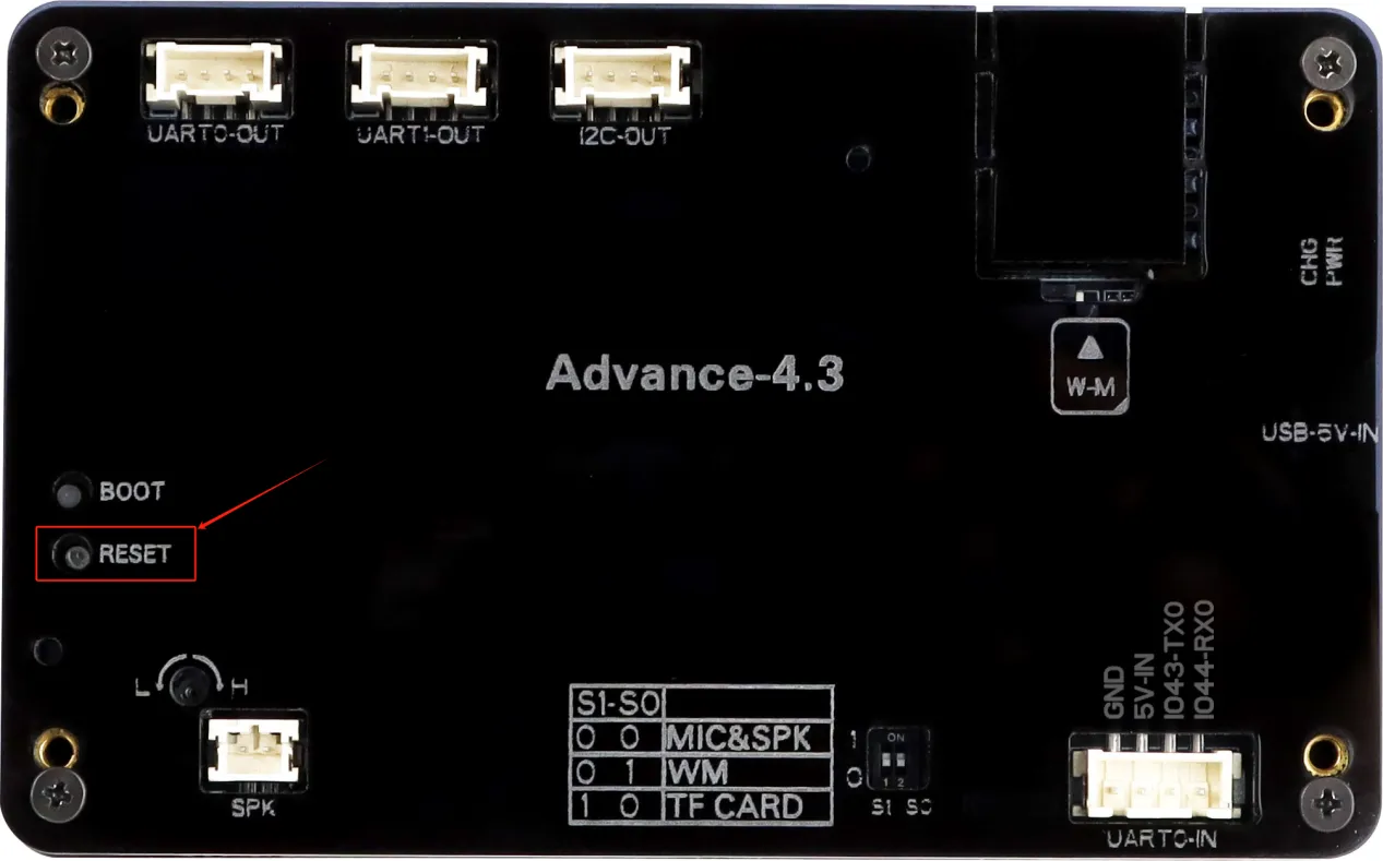
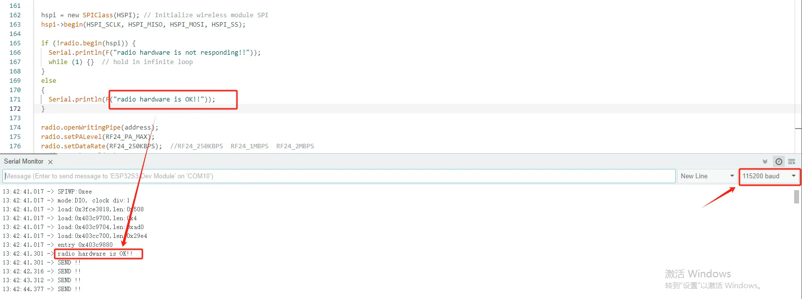
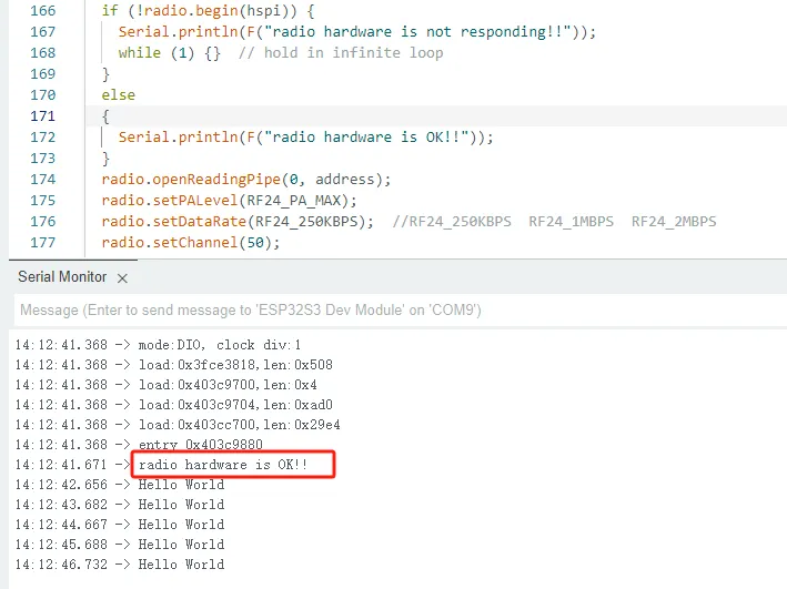
After waiting for the 4.3-inch code upload to be completed, press the RESET button.
Open the serial port debugging window
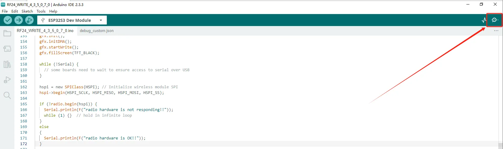
Set the baud rate to 115200, and you can see the relevant information through the serial port, so that you can know that the task of sending messages starts at 4.3 inches.
Kind Reminder:
You are currently viewing the 7-inch product of CrowPanel Advance HMI, and the version here is V1.3 / V1.4 / 1.5. (The following content is also applicable to the 5.0-inch V1.2 / v1.3 and 4.3-inch V1.1 / V1.2 / V1.3 versions.)
In terms of hardware, we use a microcontroller (STC8H1K28) to control the screen backlight, speaker on/off, and buzzer.

(However, there are other function interfaces that need to be written in the specific code, and you can refer to the complete code provided later.)
Explanation:
- 0x30 is the I2C address of the microcontroller (STC8H1K28).
- 0x5D is the I2C address of the touch IC (GT911).
- sendI2CCommand(0) means sending command 0 to the microcontroller (address 0x30) to instruct it to set the screen brightness to maximum.
For 0 mentioned above, you can replace it with the following values:
- 0 is the brightest backlight.
- 0 to 245: The screen brightness will gradually increase to the minimum value
- 245 represents turning off the screen light
Additional notes:
You can also control the following functions by sending other instructions to the microcontroller:
- It means sending the 248 command to the microcontroller (0x30) to instruct the speaker to turn on.

- It means sending the 249 command to the microcontroller (0x30) to instruct the speaker to turn off.

- You can also send command 246 to control the buzzer to turn on, and send command 247 to control the buzzer to turn off.

3 An nRF2401 is responsible for receiving messages
The task of sending messages in the 4.3 - inch device has been completed. Next, we will use the 7.0 - inch device to prepare for receiving messages sent in size 4.3.
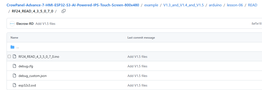
Open the READ folder.
Select the corresponding size code to open.
Call the radio.read() function to receive data.
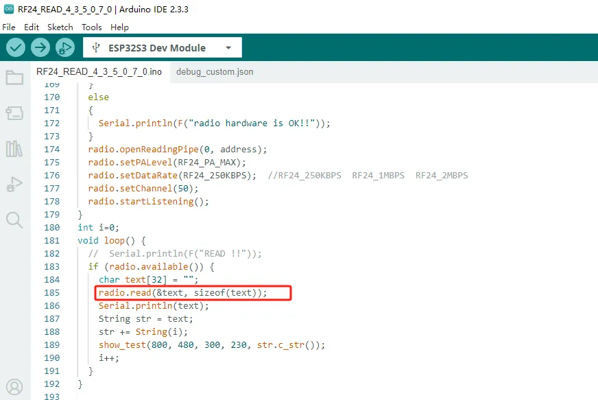
And it can display the received data on the screen.
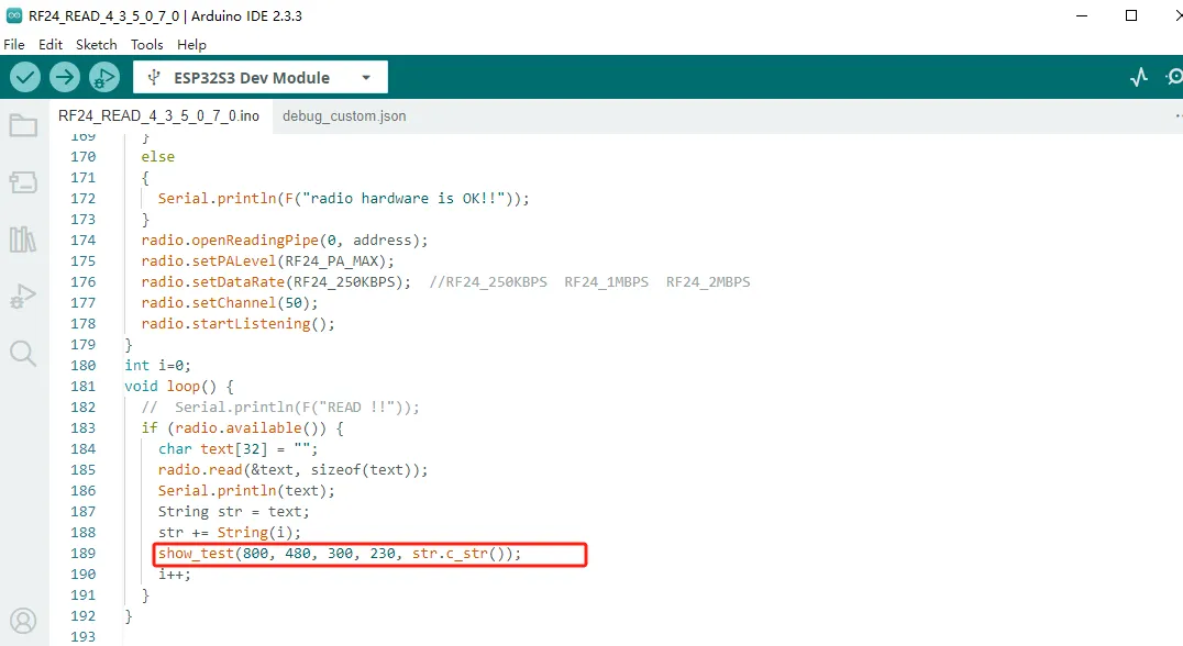
Among them, the first and second parameters in the show_test function interface are the resolutions of products of different sizes used.
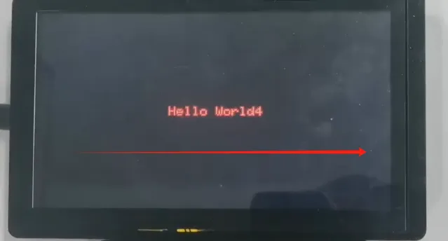
The third parameter is the starting coordinate of the horizontal axis displayed on the screen (0-800)
It can be observed that the maximum range of the starting horizontal and vertical coordinates should not exceed the maximum resolution.
Please reserve a certain spatial distance to display the text.
7.0 '' 5.0 '' 4.3 '' Horizontal coordinate range: 0-800
3.5 '' horizontal axis range: 0-480
2.8 '' and 2.4 '' horizontal axis range: 0-320
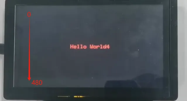
The fourth parameter is the starting coordinate of the vertical axis displayed on the screen. (0-480)
7.0 '' 5.0 '' 4.3 '' Vertical coordinate range: 0-480
3.5 '' vertical coordinate range: 0-320
2.8 '' and 2.4 '' vertical coordinate range: 0-240
The fifth parameter is the text content that needs to be displayed at the starting coordinates you have set.
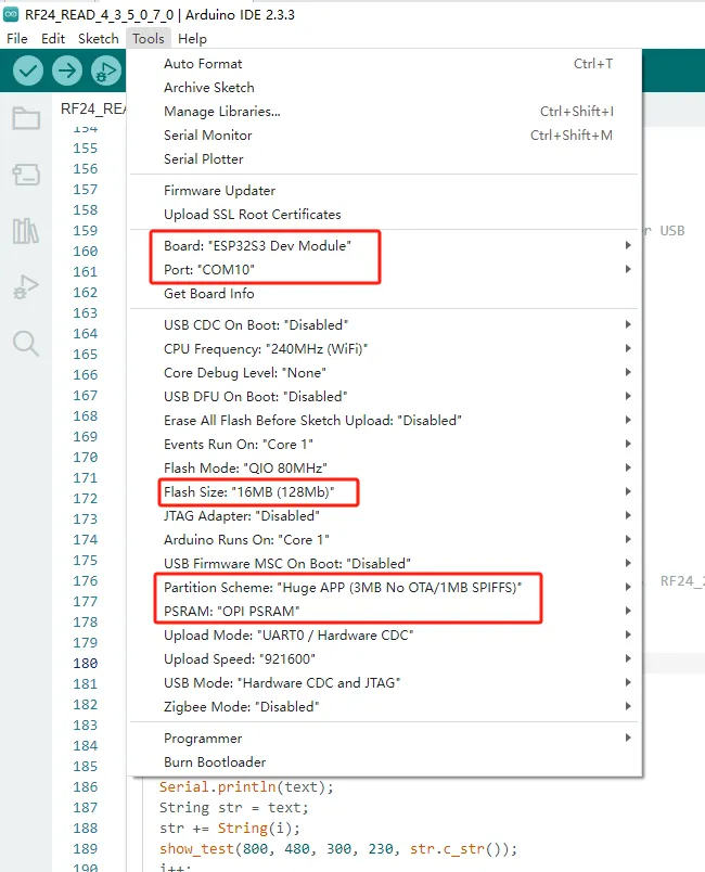
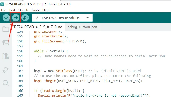
Set up the code running environment and subsequently upload the code.
Please make sure to switch the mode to 01 wireless mode.
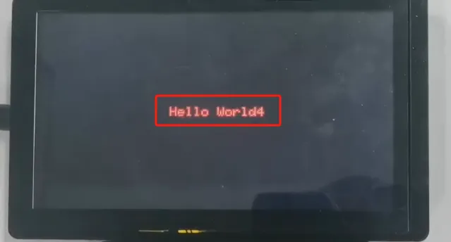
You can see that Hello World has received it.
4 Results Display
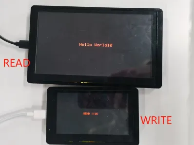
The code upload is complete. Next, let's see the actual effect.
After waiting for the code upload to complete, insert the nRF2401 wireless module into the W-M slot.
Send messages using the 4.3 - inch device and receive messages using the 7.0 - inch device.
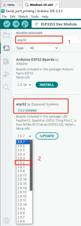
If your code compiles incorrectly, you can check if the ESP32 version number is correct. The ESP32 version number we need for this lesson is 3.0.2.
Secondly, please pay attention to replacing the corresponding size library file.
Select the appropriate library file based on the product screen size
Click the link below to download the corresponding library file.
Library file link:
If you are not sure where to place the library files and how to configure them properly so that the code can correctly recognize these library files, please refer to the operation steps in the first lesson.