Elecrow nRFLR1121 Wireless Transceiver Module-Integrates Nordic nRF52840 and Semtech SX1121 Point-to-Point Communication
In this lesson, we will focus on how to use the nRFLR1121 to transmit data.
This product boasts high performance with a maximum transmit power of +20dBm, supporting a transmission rate of 1.91~62.5kbps, a sensitivity of -141dbm SF12/BW=125kHz, and a 166db link budget. It features ultra-low power consumption, with a sleep current as low as 6uA. It supports the sub-GHz and global 2.4GHz spectrum, as well as the S-band, and enables LoRa point-to-point (P2P) communication. The wireless connection supports the 850~930MHz global LoRa&LoRaWAN ISM frequency and is compatible with low-power Bluetooth, Bluetooth mesh network, NFC, Thread, and Zigbee. With built-in AT command firmware, it supports customized product development using the SDK, and the AT command set can be easily accessed via the UART interface. For long-distance communication needs, it can reach up to 10km. Additionally, it comes with rich peripherals, exposing various GPIO interfaces such as UART, I2C, and ADC, offering great flexibility. Despite its powerful features, it has a compact form factor, measuring only 20x20x3.5 mm and has obtained FCC, CE, and RoHS certifications.
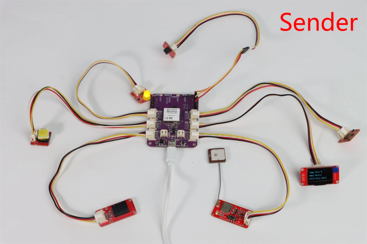
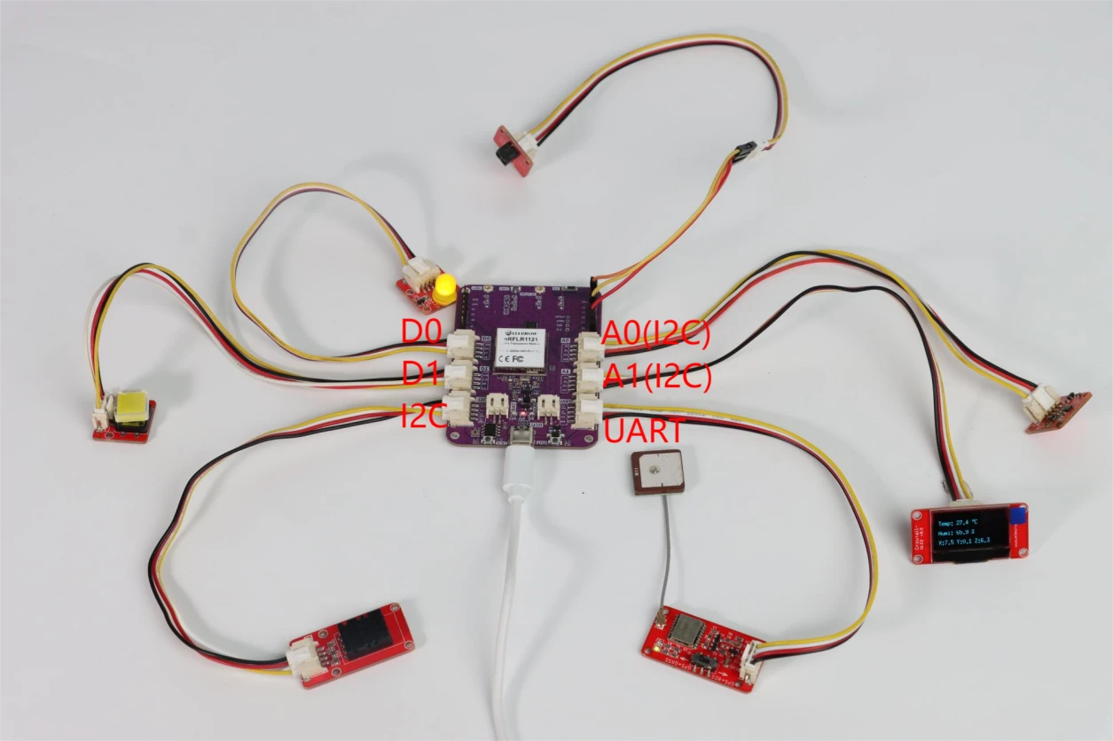
As shown in the figure below, we are using the nRFLR1121 module with each interface connected to a sensor. This setup allows us to collect data from each sensor and transmit the data to another nRFLR1121 module using LoRa technology. Finally, the received data can be viewed through the serial port.
Next, let’s explore this together.
First, open the code files.
Click the link below to download the relevant code for this module of the course.
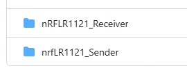
The nRFLR1121 _Sender file is used to collect sensor data and transmit it.
The nRFLR1121 _Receiver file is used to receive the data.
Let's first introduce the code structure of the sender.
We'll go through it module by module:
**Bulb:**Connected to the nRFLR1121 module's D0 interface, which corresponds to pin 26
**Button:**Connected to the nRFLR1121 module's D1 interface, which corresponds to pin 12
**DHT20 Temperature and Humidity Sensor:**Connected to the nRFLR1121 module's I2C interface, which corresponds to pins 13 and 14
**Accelerometer:**Connect to the A0 interface of the nRFLR1121 module, which is pins 28 and 29. This interface is our custom I2C interface.
**u8g2 Display:**Connect to the A1 interface of the nRFLR1121 module, which is pins 4 and 5. This interface is also our custom I2C interface. If you want to use A0 and A1 as other interfaces, you can customize them as well.
**IR Receiver:**Connect to the header pins at the top right corner of the nRFLR1121 module. We choose pin 20 to connect to the IR module. The pin selection can be customized by you as long as the code matches.
**GPS Module:**Connect to the UART interface of the nRFLR1121 module, which corresponds to pins 22 and 24. Here, it is only used for serial communication to obtain data from the GPS module.
Next, let’s first talk about the implementation of the bulb and the button.
Light bulbs and buttons
The main function is to turn the bulb on or off by pressing the button.
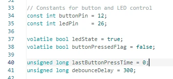
This code is the core definition section for controlling the LED through button input: Firstly, the GPIO12 pin (connected to the button) and the GPIO26 pin (connected to the LED) are defined using the const int constant; the volatile modifier is applied to ledState (which records the current switch state of the LED, initially set to on) and buttonPressedFlag (the flag for button triggering, initially set to untriggered), ensuring that the variables are updated synchronously in the interrupt and the main program; then, lastButtonPressTime (which records the last valid button press time) and debounceDelay (300 milliseconds for debouncing delay) are defined, which are combined to implement the button debouncing function, avoiding LED false triggering caused by physical button jitter, providing basic variable support for subsequent interrupt triggering, state switching and debouncing logic.
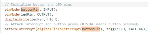
This code is the core logic for initializing the button and LED: Firstly, the button pin (buttonPin) is set to input mode and the LED pin (ledPin) is set to output mode. Then, using digitalWrite(ledPin, HIGH), the LED is powered on by default and lit. Subsequently, the attachInterrupt function is used to bind an external interrupt to the button pin. By using digitalPinToInterrupt, the physical pin is converted into an interrupt number. The interrupt trigger mode is specified as FALLING (i.e., triggered when the button is pressed), and after triggering, the toggleLED interrupt service function is automatically executed to complete the interrupt configuration for controlling the LED with the button.
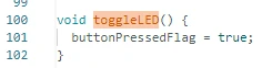
This function is the interrupt service routine for the button. Its function is extremely simple and crucial: When an external interrupt occurs (the button is pressed), the function only performs the operation of setting the buttonPressedFlag flag to true. It does not directly operate on the LED, delay, or other time-consuming logic within the interrupt. This ensures that the interrupt function executes quickly without blocking the system operation. The main loop will later handle the LED flip and debouncing by detecting this flag. It is a standard way of implementing "light trigger and main loop processing" in interrupt design.
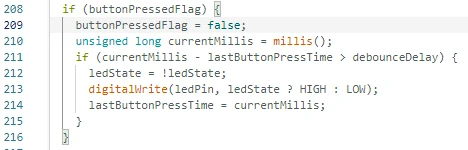
This code is the core logic for handling the LED flip upon button press in the main loop: First, it checks whether the buttonPressedFlag is true (indicating that the button has been pressed and triggered an interrupt). If so, it immediately resets the flag to false to avoid duplicate processing. Then, it obtains the current time and checks whether the interval between the current valid button press and the previous one exceeds 300 milliseconds (the debounce time). If this condition is met, it flips the ledState variable and controls the high and low levels of the LED pin based on the new state. Finally, it updates the time of the last valid button press, achieving a fast response to the button interrupt while completing the debounce of the button non-blockingly, preventing the LED from frequently switching due to button jitter.
DHT20 Temperature and Humidity Sensor
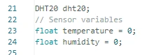
Create a control object for the DHT20 temperature and humidity sensor, and define two floating-point variables, temperature and humidity, specifically for storing the temperature and humidity values read from the sensor.
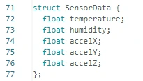
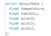
Define the sensor data structure, integrating temperature, humidity and acceleration data together to facilitate unified management, printing, display and wireless transmission.
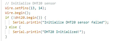
Configure the I2C communication pins of DHT20 and start the I2C bus to initialize the sensor; if successful, print a prompt on the serial port; if unsuccessful, output an error message to facilitate problem troubleshooting.
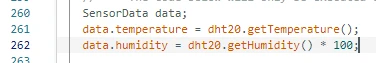
In a 1-second scheduled task, call the sensor function to read the current temperature and humidity, and assign the values to the structure variable. Multiply the humidity by 100 to convert it into a percentage format.
Accelerometer
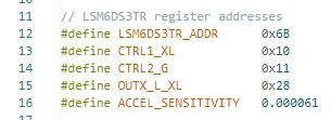
Define the I2C address of the sensor, the address of the control register, the address for data reading, as well as the sensitivity conversion coefficient, which are used for subsequent configuration and reading of the original data and conversion into actual physical units.
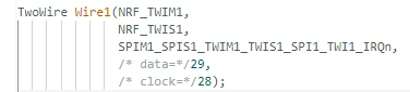
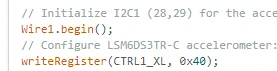
Create an independent I2C bus named Wire1, using pins 28 (for the clock) and 29 (for the data), specifically for communicating with the acceleration sensor, to avoid conflicts with other sensor buses.
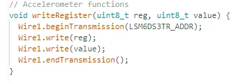
The configuration values are written to the designated register of the acceleration sensor via I2C, which is used to start the sensor, set the sampling rate and the measurement range.
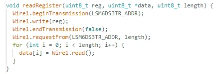
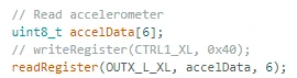
Read 6 bytes of raw data (2 bytes for each of the X, Y, and Z axes of acceleration) from the specified address of the sensor, for use in subsequent calculations.
In the sensor data structure, define three variables: accelX, accelY, and accelZ, which are used to store the converted values of the three-axis acceleration.
Start the second I2C bus, write the configuration to the sensor control register, set the sampling rate to 104Hz and the measurement range to 4g, and then let the sensor start working.
The sensor's 6-byte raw data is read once every second, corresponding to the low and high bytes of the X, Y, and Z axes respectively.
Combine the high and low bytes into a 16-bit original value, then convert it into the standard unit m/s² based on the sensitivity coefficient and the gravitational constant, and store it in the structure.

U8g2 display screen
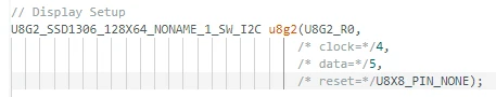
Create a display object, specifying the driver chip SSD1306, resolution 128x64, software I2C communication, clock pin 4, data pin 5, and no reset pin.
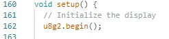
In the setup, start the display screen, complete the hardware initialization, and make the screen enter the displayable state.
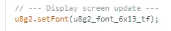
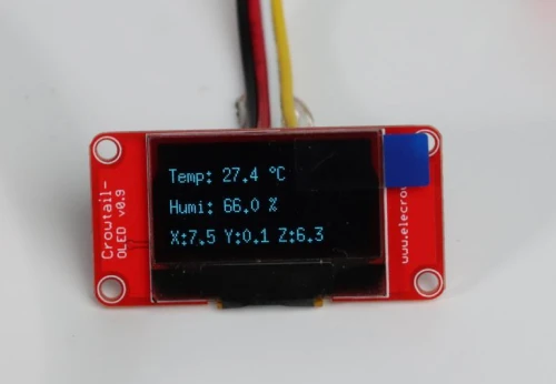
Set the text font size to 6x13, ensuring clarity and readability, and use it to display temperature, humidity and acceleration data.
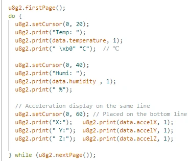
Activate the page refresh mode of the display screen and prepare to start drawing the content.Set the cursor to the 0th column and 20th row on the screen, display the temperature data, keep one decimal place, and include the unit "℃".
Move the cursor to the 0th column and the 40th row, display the humidity value, keep one decimal place, and use the % unit.Move the cursor to the 60th line at the bottom of the screen. Display the acceleration values for the X, Y, and Z axes, each with one decimal place.
Complete all the content drawing and actually output the data onto the screen for display.
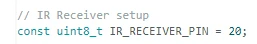
IR Receiver
Set the GPIO pin connected to the infrared receiving module to 20, which is used to receive signals from the infrared remote control.
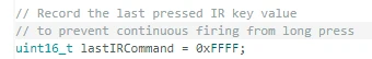
Save the last successfully recognized key value to filter out long-press repeated triggers and ensure that each key press is executed only once.
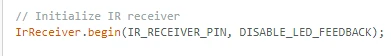
In the setup mode, enable the infrared receiving function, turn off the receiving indicator light, and start listening for the remote control button presses.
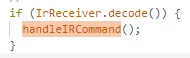
In the loop, continuously check if infrared data is received. Once received, call the processing function to decode it.
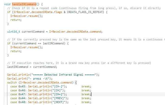
The handleIRCommand function is the core processing function of infrared remote control. It first filters out long-press repeat codes and continuous trigger signals, then decodes to obtain the key value, matches the remote control keys through a switch statement and prints the corresponding key name on the serial port, and finally restarts the infrared receiver to wait for the next signal, achieving a stable and error-free infrared key recognition function.
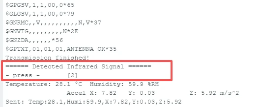
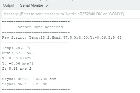
Here, I pressed the key value "2" on the infrared remote control.
After receiving the infrared signal, the corresponding information will be displayed in the serial monitor as shown below.
GPS positioning module
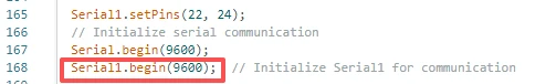
Since the GPS module is connected to the UART interface, we initialize the UART interface pins 22 and 24.

Then, initialize the baud rate required for the serial communication.
This code is the core logic for achieving bidirectional data forwarding between the main serial port (USB serial port) and the GPS module's serial port (Serial1): When Serial1 detects data sent by the GPS module, it reads the data byte by byte and prints it to the computer through the main serial port, facilitating the viewing of the original GPS positioning information; When there is data sent from the computer to the main serial port, it will read the data byte by byte and forward it to Serial1, enabling bidirectional communication with the GPS module, and completing the functions of receiving and echoing GPS data as well as transmitting instructions.
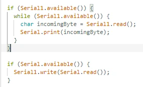
As you can see here, we haven't processed the received GPS signals. If you're interested, you can explore it further to obtain the desired latitude and longitude information.GPS data can only be received outdoors.

LoRa module
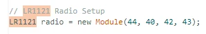
Create an object for the LoRa module, configure the control pins such as chip selection, interrupt, and reset, and establish the hardware connection.
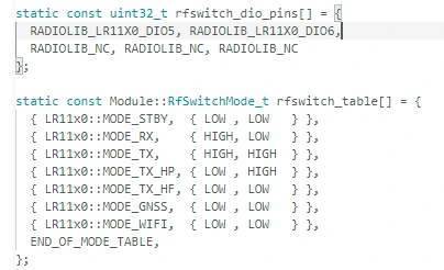
Configure the pins for the radio frequency switch and the working mode to enable the LoRa module to switch between sending, receiving and sleep states normally.
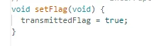
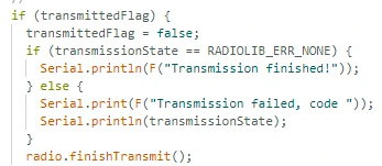
After a packet of data is sent via LoRa, this function is automatically triggered and the flag indicating the completion of the transmission is set to true.
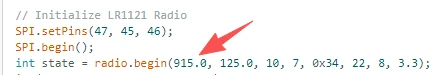
Initialize SPI communication, configure LoRa parameters (frequency band 915MHz, bandwidth 125kHz, etc.), and start the wireless module.Make sure that the parameters at the sending end and the receiving end are exactly the same and operate on the same frequency band.
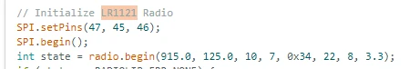
Import the RF switch mode into the module to ensure the normal operation of the transmitting and receiving circuits.

After the sending is completed, the setFlag function will be automatically called to notify the main program that the sending is over.

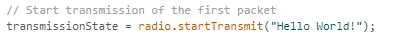
After the initialization is completed, a test data message is sent first to start the wireless communication.
After detecting the completion flag of the transmission, clear the flag, print the status, terminate this transmission, and prepare for the next communication.
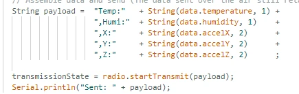
Every second, the temperature, humidity and acceleration data are concatenated into a string and sent out via LoRa wireless.
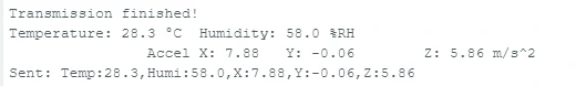
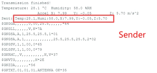
This code first concatenates the temperature, humidity and three-axis acceleration data in the structure, which are rounded to the specified decimal places, into a formatted string data packet called payload. Then, it sends the data packet through the LoRa wireless module and simultaneously prints the complete content of the sent data on the serial port, achieving the functions of formatting sensor data, wireless transmission and local log viewing.
As shown in the following figure effect
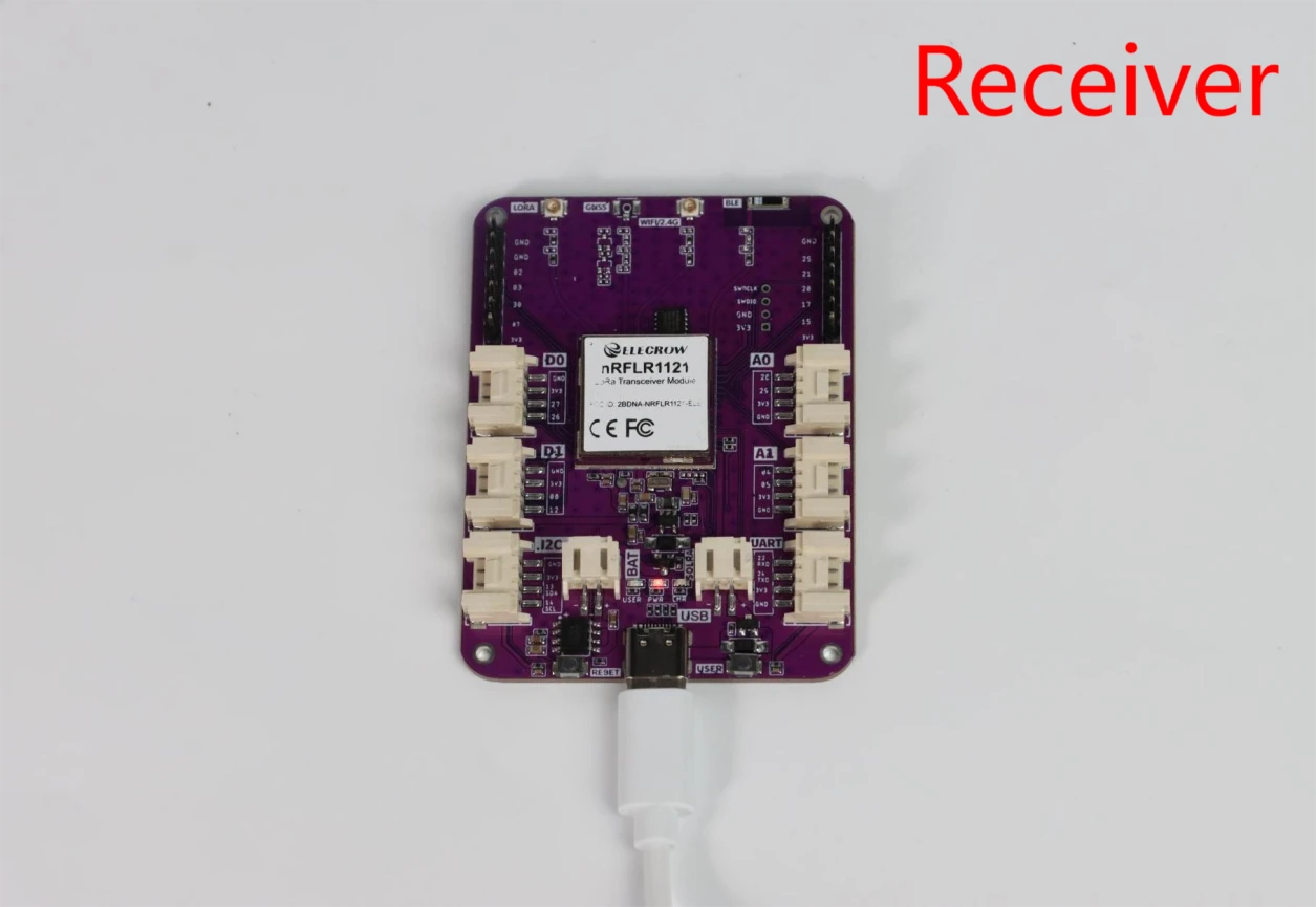
Receiving end
The receiver also starts by initializing the pins for the LoRa module.

Next, the most important thing is that the frequency band must match the one used by the transmitter.
transmitting terminal :
receiving end:
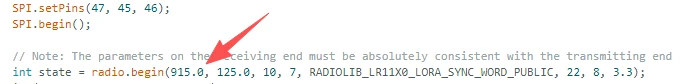
This LoRa receiver code establishes a wireless connection by strictly matching all communication parameters of the sender, including the frequency of 915.0 MHz, bandwidth of 125.0, spreading factor of 10, encoding rate of 7, and synchronization word. It also enables the reception of interrupts to listen for data.
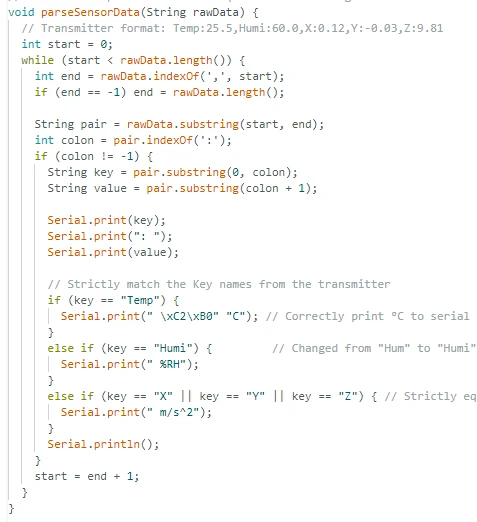
The parseSensorData function is used to parse the sensor string in key-value pair format sent by the transmitting end. By splitting the comma and colon, it extracts the key fields such as Temp, Humi, X/Y/Z and their corresponding values segment by segment. Then, based on the field type, it automatically matches the units of temperature °C, humidity % RH, and acceleration m/s². Finally, it formats and outputs the data to the serial port, making the original data clear and readable, achieving a complete correspondence with the data format of the transmitting end and precise parsing.
After analyzing the data, you can see the data you obtained from the serial port output.
By comparing the data transmission and reception at the sending end and the receiving end, one can clearly understand it.
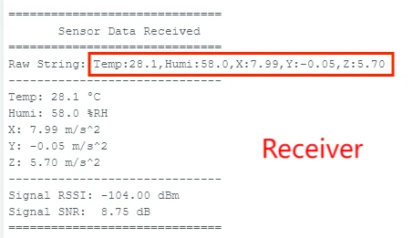
Perfect! The LoRa module successfully transmitted the data!This concludes the explanation of the transmitter and receiver code.
Notes:
1.Install the development version
Lastly, here are some points to keep in mind during actual operation:Since the nRFLR1121 uses the nRF52840 as the main control chip, you need to install the nRF52 development board.
Open the Arduino IDE.
Go to File > Preferences (or Arduino > Preferences, depending on your operating system).
In the "Additional Board Manager URLs" field, add the following URL:
https://adafruit.github.io/arduino-board-index/package_adafruit_index.json
If there are already other URLs, make sure to separate them with commas or new lines.
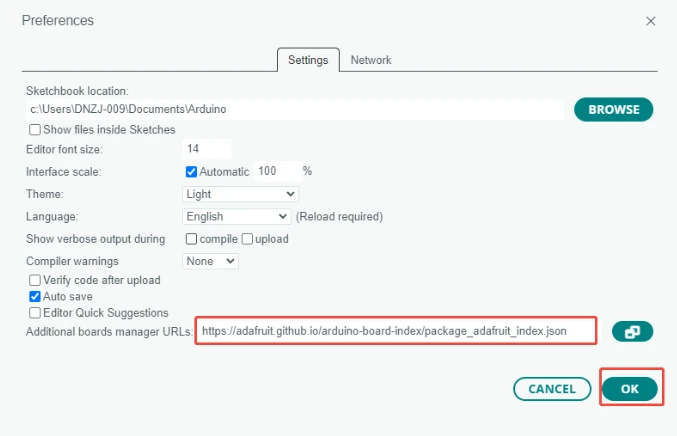
Click "OK" to save the settings.
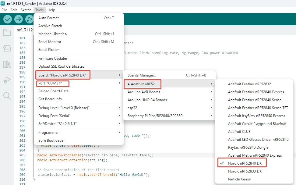
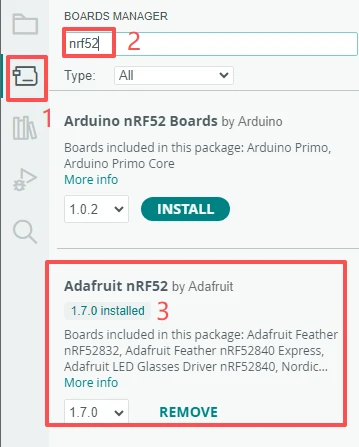
Navigate to Tools > Board > Boards Manager.
In the search box, type "Adafruit nRF52", find "Adafruit nRF52 by Adafruit", and click "Install".(Here we are using version 1.7.0.)
Once installation is complete, you can select the appropriate board model from the Tools > Board menu.
2.Use the library files we provided
Click on the link to our library file for download:
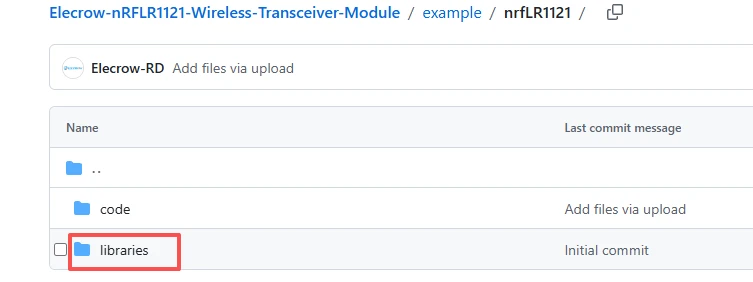
After the download is complete, place these four library files in this directory on your computer.
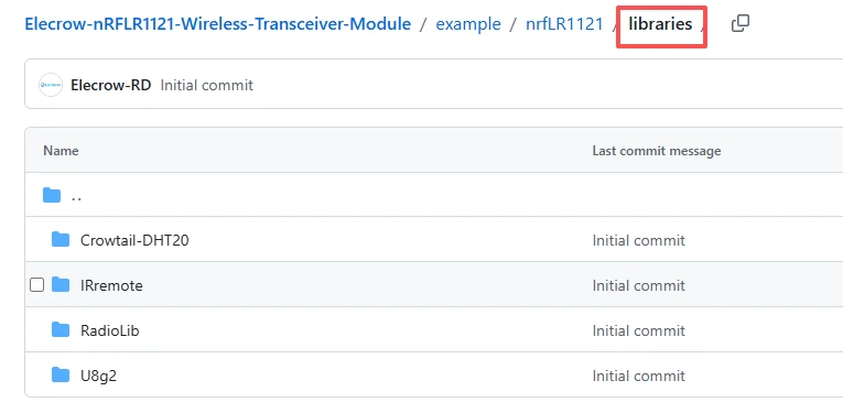
Place these four library files in the following path on your computer, in the "libraries" folder.

3.Pay attention to the configuration during the flashing process.