3. Use SquareLine Studio and LVGL libraries to create a UI interface to light the lights
1. Introduce LVGL
LVGL (LittlevGL) is an open-source, lightweight, high-performance embedded graphics library designed specifically for devices with limited resources. It supports multi platform porting, provides rich controls, animations, touch support, and highly customizable styles, suitable for fields such as smart homes, industrial equipment, medical instruments, etc. LVGL is centered around modular design and can run on bare metal or operating systems, accelerating GUI development through powerful community support and tools such as SquareLine Studio.
SquareLine Studio is a next-generation user interface (UI) solution for individuals and professionals, allowing users to quickly and easily design and develop aesthetically pleasing UI for embedded devices. This software provides integrated design, prototyping, and development capabilities, supporting the export of platform independent C or MicroPython code for LVGL (Lightweight Graphics Library), which can be compiled and run on any vendor's device.
2.Install SquareLine Studio
2.1 Installation Guide
Enter the https://squareline.io/ to download the SquareLine installation file.
Download the version 1.4.0
Double-click the setup.exe file.
Click install.
Wait for installation.
Installation finish.
There is a 30-day trial period for the first time you use it. Please follow the prompts to register an account. You will continue to use it when you log in to your account next time.
2.2 Software Function Introduction
Open the software
The historical project page: open the project built earlier.
Create a project page: choose different platforms according to different hardware of the project.
When select the Arduino framwork, there's only one option "Arduino with TFT_eSPI". By choosing this, the squareline studio will generate a template code suitable for the TFT_eSPI library. However, squareline studio not only supports the TFT_eSPI library, it supports a variety of libraries to suit different hardware and application needs. For example, Adafruit_GFX library, LovyanGFX etc.
After using SLS to generate UI code, we then use different graphics libraries according to different hardware and modify the corresponding code to display the content you design.
Example page. This page has several official examples for reference.
The project settings bar is used to make basic settings for the project, including property settings such as project name, screen size, display angle, etc.
Note: Please select the corresponding resolution and color depth according to the screen specifications.
①Toolbar, including File, Export, and Help. Basic file operation bar, create or open files, export UI files and other operations. Click help and there are related introductory documents.
②Screen bar, the project screen will be listed here.
③Widget area, all widgets are here and can be selected and used according to project needs.
④Hierarchy area, it will show every widget used in each screen.
⑤This area shows the actual display effect, you can adjust the widgets or screen here.
⑥Material column, the added materials are displayed here.
⑦Setting bar, where you can make basic settings for each part, including the basic attributes and trigger operations of the part.
⑧Theme bar, different themes can be set.
3 Use SquareLine Studio to create UI control interfaces
Firstly, open the SquareLine Studio software and create a case study
Choose the correct resolution based on the different sizes you are using
Here, I take a 3.5-inch screen as an example. After determining the resolution, I fill it in
After selecting the parameters, click Create
Open the photo of the desk lamp we provided and add it in. (Of course, you can also choose the image you want to use)
The lamp_28 image size is available for both 2.4-inch and 2.8-inch screens.
Table_1amp image sizes are available for 3.5-inch, 4.3-inch, 5.0-inch, and 7-inch screens.
After adding it, drag and drop the image in.
The task we need to complete is to turn on and off the lights by clicking on the buttons on the graphical interface. So we need to design two buttons
From the left sidebar, select Button and drag it into the interface.
You can adjust the border of the button with the mouse, which can adjust the size of the button, and you can also drag and drop the button to adjust its position.
Then, by selecting Background, choose the background color of the Button.
We have made the button patterns, and now we need to add labels to the button patterns in order to distinguish their functions.
Drag and drop from the left sidebar, select Label, and drag into the interface.
Modify the text content of the label
And modify the font size and text color of the text
The Button and Label have been designed. Click on the Hierarchy in the right-hand column and drag the Label onto the Button line to merge them into one.
At this point, if you drag the buttons again, you will find that they are dragged together
Next, we will copy a completed button, right-click, and paste it in.
Click the second button ON to change the text content to Off. Used to achieve the effect of turning off lights.
4 Add functions to the buttons to enable them to turn on and off lights
Select 'event' to add in the right sidebar
Select 'released' as the triggering condition and 'Call function' as the action.
After selecting, click ADD.
And add a function name to the CALL Function. (Customization is sufficient)
Similarly, add an event to the Off button. The operation process is the same as above.
After adding, run
5 UI interface design completed, exporting UI files for easy use in subsequent code
Click on Project Setting
Set export path
Complete the setup and export file
Copy and paste the exported code into the code folder we need to open
Then double-click 3_5LVGL.ino and open it using Arduino IDE
6 Connect the light bulb and add code to control the light bulb to turn on and off
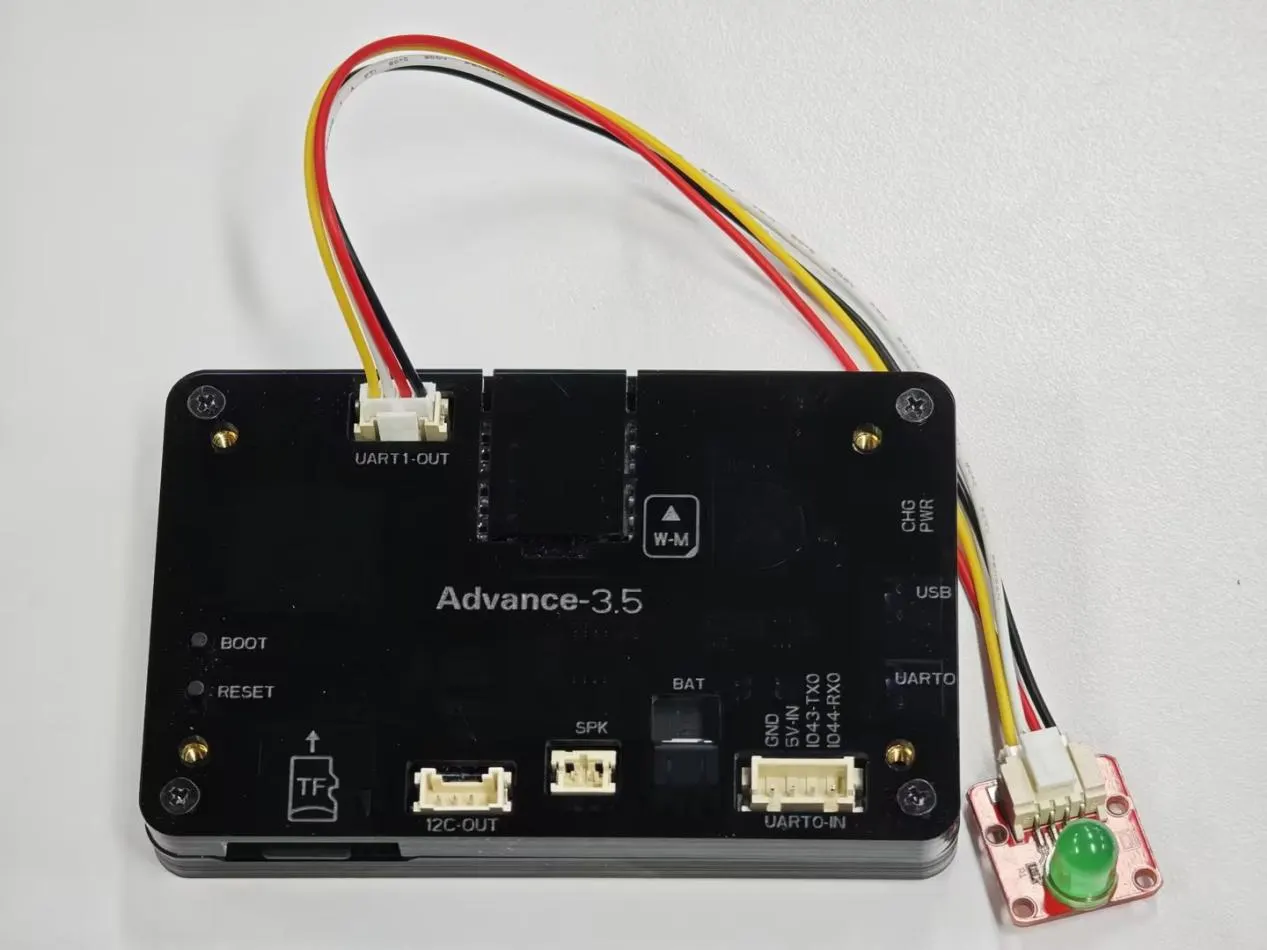
Connect the light bulb at the UART1 interface
This is the diagram for connecting the bulb of the 3.5-inch V1.0 version.
This is the diagram for connecting the bulb of the 3.5-inch V1.2 version.
Observing the schematic diagram of this size, it is known that the pin for UART1 to control the light bulb to turn on and off is 18
So in the code, set pin 18 as the output mode.
A large-sized screen requires setting 19 pins as the output mode.
And add the function of turning on and off the light bulb in the ui_ event. c file.
(When the On button is clicked, the light is on; when the Off button is clicked, the light is off)
7 Configure the code running environment and upload the code
(!! Before uploading the code, please use different library files according to the size you are using. You can review the content of Lesson 2)
(For large-sized screens of 4.3 inches, 5.0 inches, and 7.0 inches, be sure to switch the mode to 0 1 state before uploading the code, because the pins of UART1 and W-M mode are both used in 0 1 mode, so that you can use the pins of UART1)
So you can see the UI interface you just designed
You can click the On and Off buttons to control the on/off of the lights
8 Code presentation
Click the link below to download the complete code:
Here is a new program (pwn version) for adjusting the backlight, which allows you to control the screen brightness by using PWM. Here is the program to adjust the brightness of the backlight:
// Select PWM channel
int pwmChannel = 0;
int pwmFreq = 5000;  // 5kHz
int pwmResolution = 8; // 8-bit resolution(0-255)

int pwmPin = 38;  // Set the pins, assuming you are using GPIO38

void setup() {
  // Configure PWM channels
  ledcSetup(pwmChannel, pwmFreq, pwmResolution);

  // Connect the PWM signal to the specified pins
  ledcAttachPin(pwmPin, pwmChannel);
}

void loop() {

  // Adjust PWM duty cycle  (0-255)
  for (int dutyCycle = 0; dutyCycle <= 255; dutyCycle++) {
    ledcWrite(pwmChannel, dutyCycle); // Setting the Duty Cycle
    delay(100); // Delay to visualize changes
  }
}
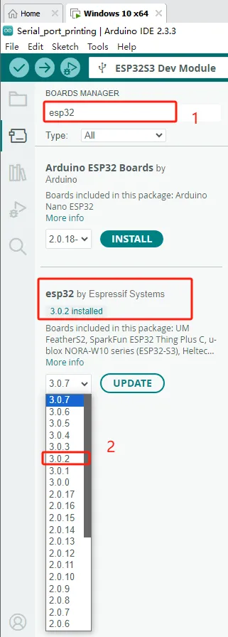
If your code compiles incorrectly, you can check if the ESP32 version number is correct. The ESP32 version number we need for this lesson is 3.0.2.
Secondly, please pay attention to replacing the corresponding size library file.
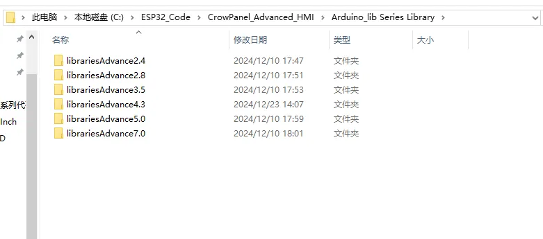
Select the appropriate library file based on the product screen size
Path reference:C:\ESP32_Code\CrowPanel_Advanced_HMI\Arduino_lib Series Library
I will use the Advance 7.0-inch product as an example for operation
Copy the Libraries Advanced 7.0 folder
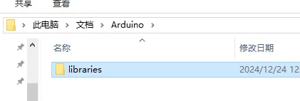
Open Arduino IDE runtime library file path
Reference path: C:\Users\14175\Documents\Arduino
Delete the existing libraries folder
Paste the copied library Advanced 7.0 folder into this path
Change the folder name to the original libraries
Library update completed, restart Arduino IDE.
When using other sizes, changing the library file is the same operation


