Lesson4 The temperature and humidity sensor receives data in real time
Welcome to the Lesson 4 of learning.
This lesson will use the IIC interface and of this series of products to collect data from temperature and humidity sensors. In this lesson, we will use the knowledge of LVGL graphics library from Lesson 3 to create an interactive interface.
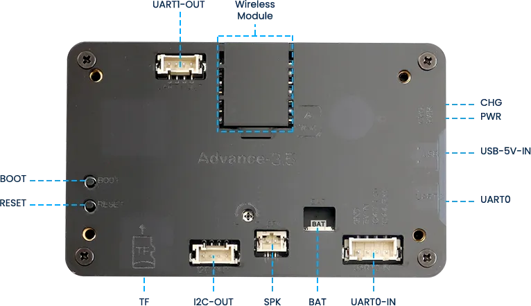
1 Introduce product ports
USB interface: used for power supply, serial communication, and automatic programming.
UART0-IN interface: supports power supply, serial communication, and entering manual burning mode by pressing BOOT+RESET; Other functions are consistent with the USB interface.
UART0-OUT interface: used for external power supply and serial communication.
UART1-OUT interface: uses soft serial port and supports configuring IO function.
I2C-OUT interface: connects RTC chip, extended IO chip (for screen backlight, touch screen reset, power amplifier pin control) and wireless module, only supports I2C communication.
2 UI interface design
The temperature and humidity sensor needs to support IIC communication. In order to provide everyone with an intuitive observation, I will use LVGL to create an interactive interface.
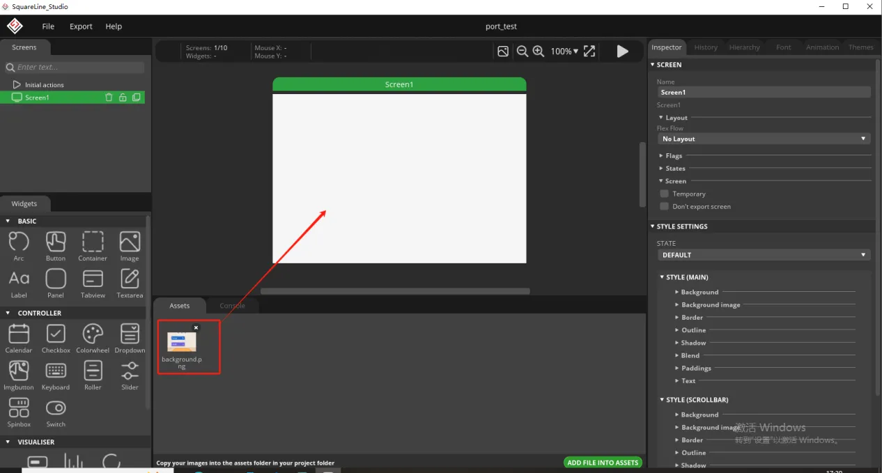
Open SquareLine Studio. If you haven't installed it, you can review the introduction of LVGL in Lesson 3.
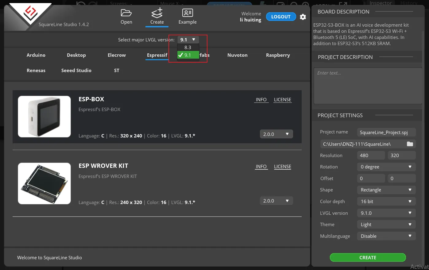
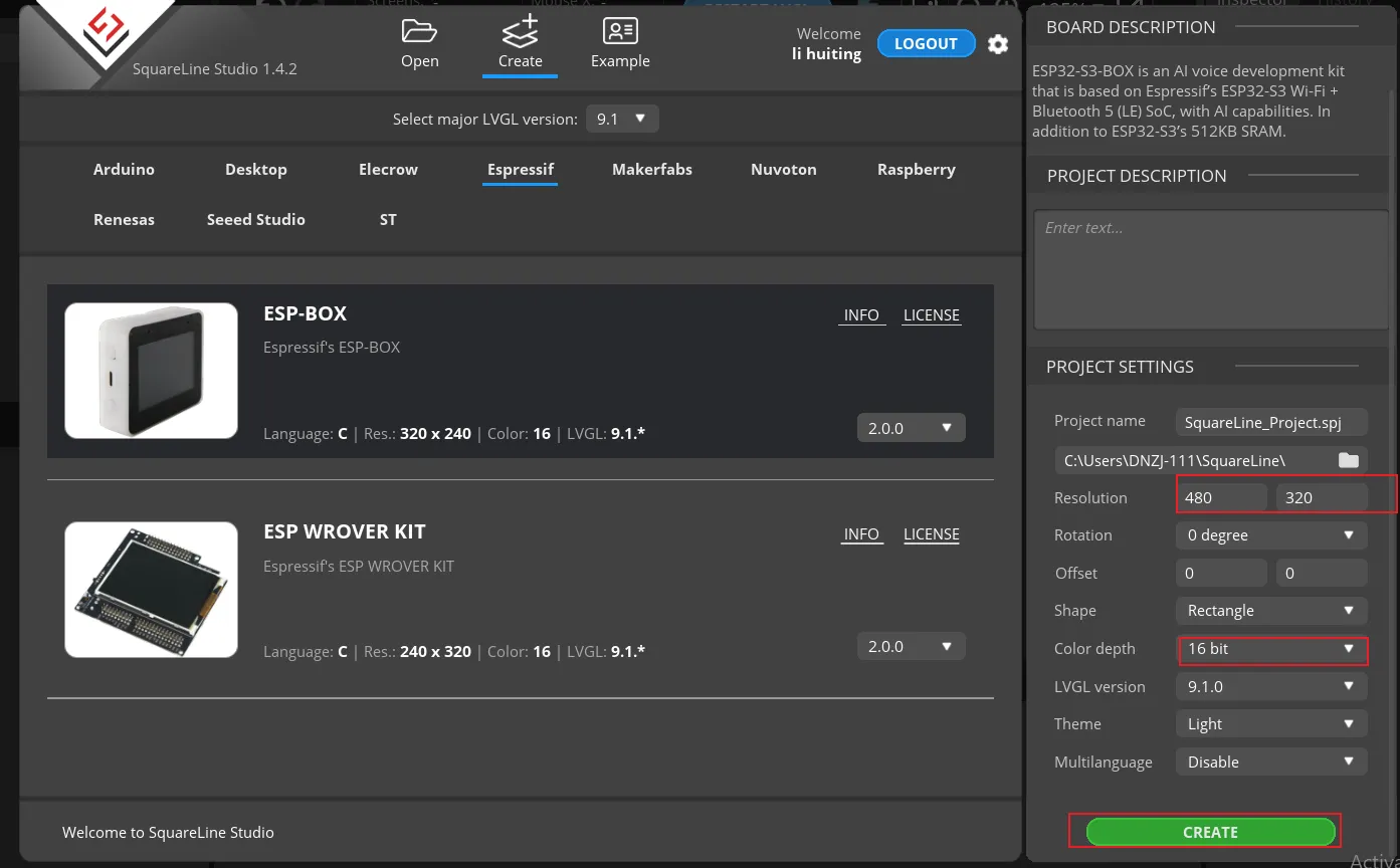
Create Espressif project
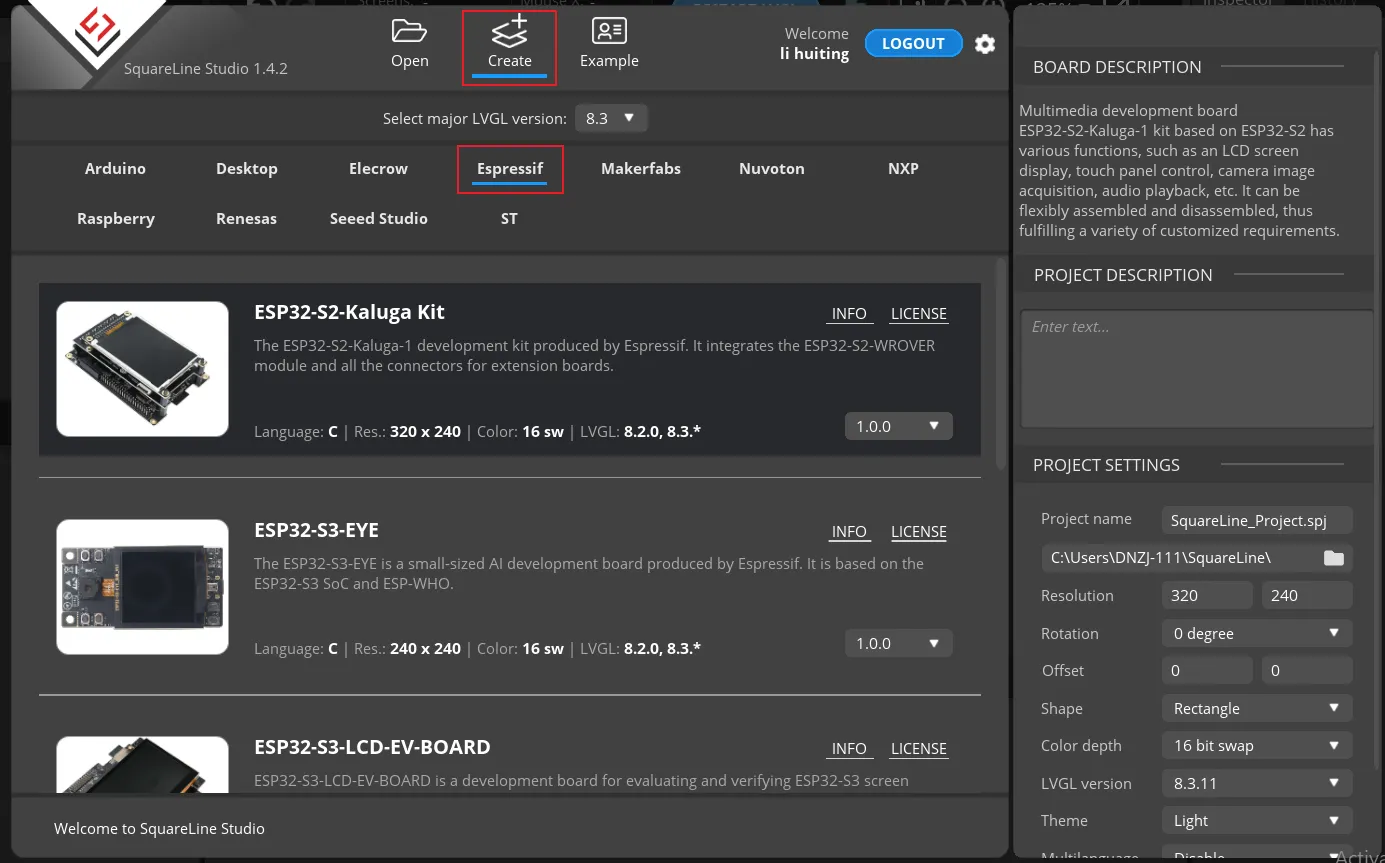
Note: Use version 9.1.0 for small-sized items, and use version 8.3.11 for large-sized items.
Modify the file name and file storage path according to your needs (customization is sufficient)

Modify the appropriate resolution based on the different sizes you are using.
Finally, click on 'Create' to proceed.
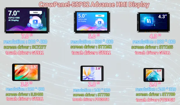
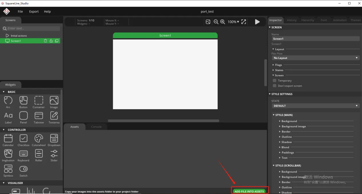
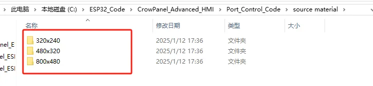
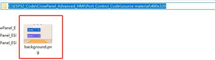
Add the background image we provide based on the resolution required for the size you are using (choose different resolutions for different sizes, refer to the resolution size used for different sizes in Lesson 3)
Here is the corresponding image asset download link for each screen size:
- 320*240:https://www.elecrow.com/download/product/CrowPanel/ESP32-HMI/2.4-DIS03024H/Arduino-Tutorial/ESP32-LVGL-Assets-2.4.zip
- 480*320:https://www.elecrow.com/download/product/CrowPanel/LVGL-Assets-480x320.zip
- 800*480:https://www.elecrow.com/download/product/CrowPanel/LVGL-Assets-800x480.zip
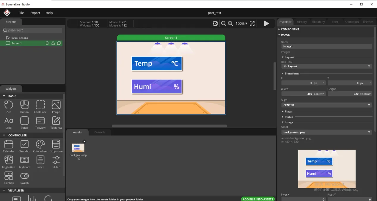
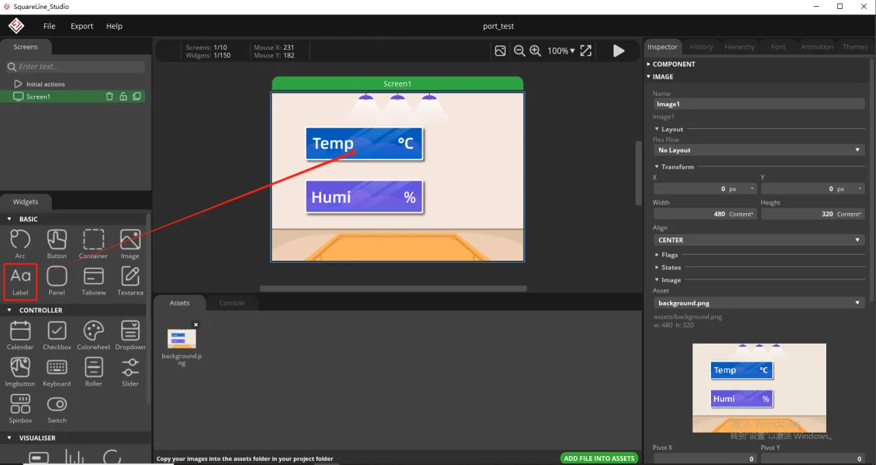
Add background image to the box.
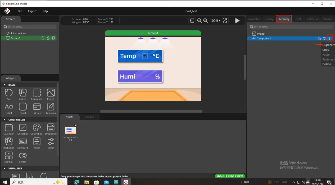
Since we need to display the temperature and humidity values on the screen, we need to add text in the two boxes for temperature and humidity.
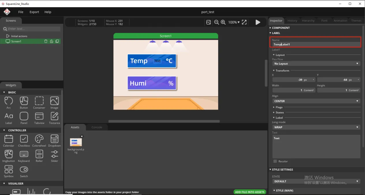
To distinguish between the other text labels that need to be created next, give this label a name to distinguish it.
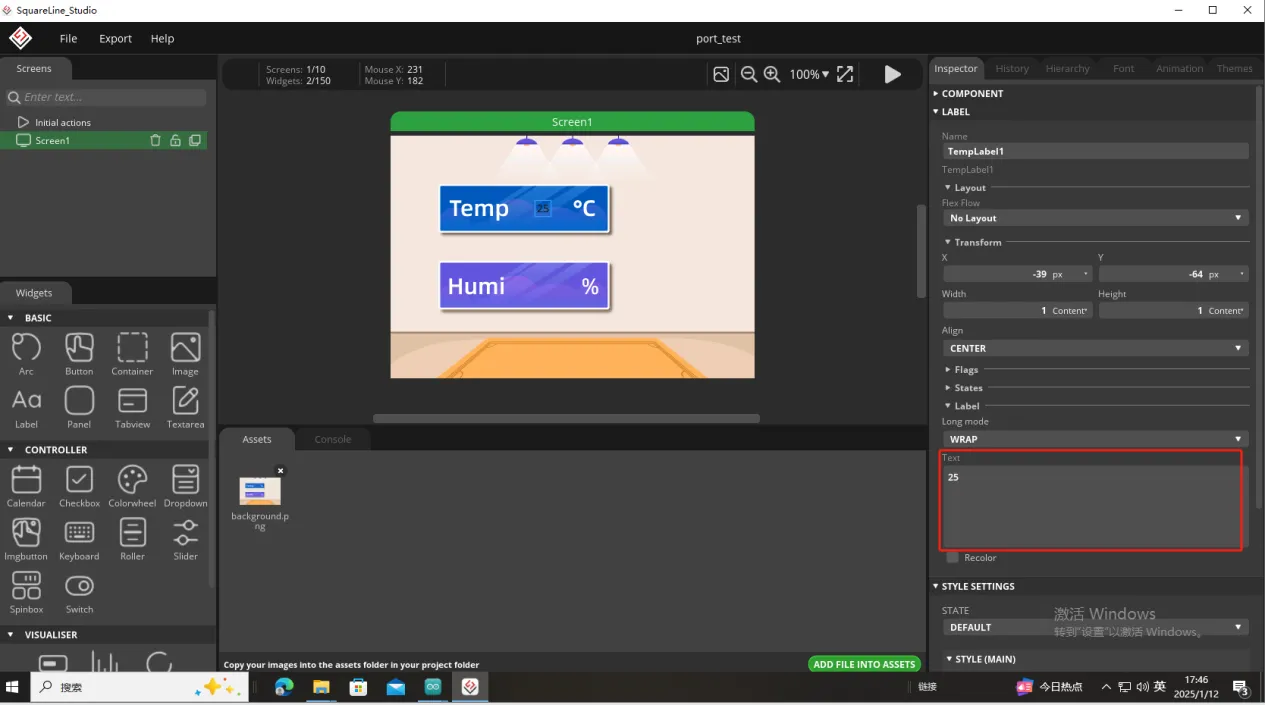
And fill in a default temperature value
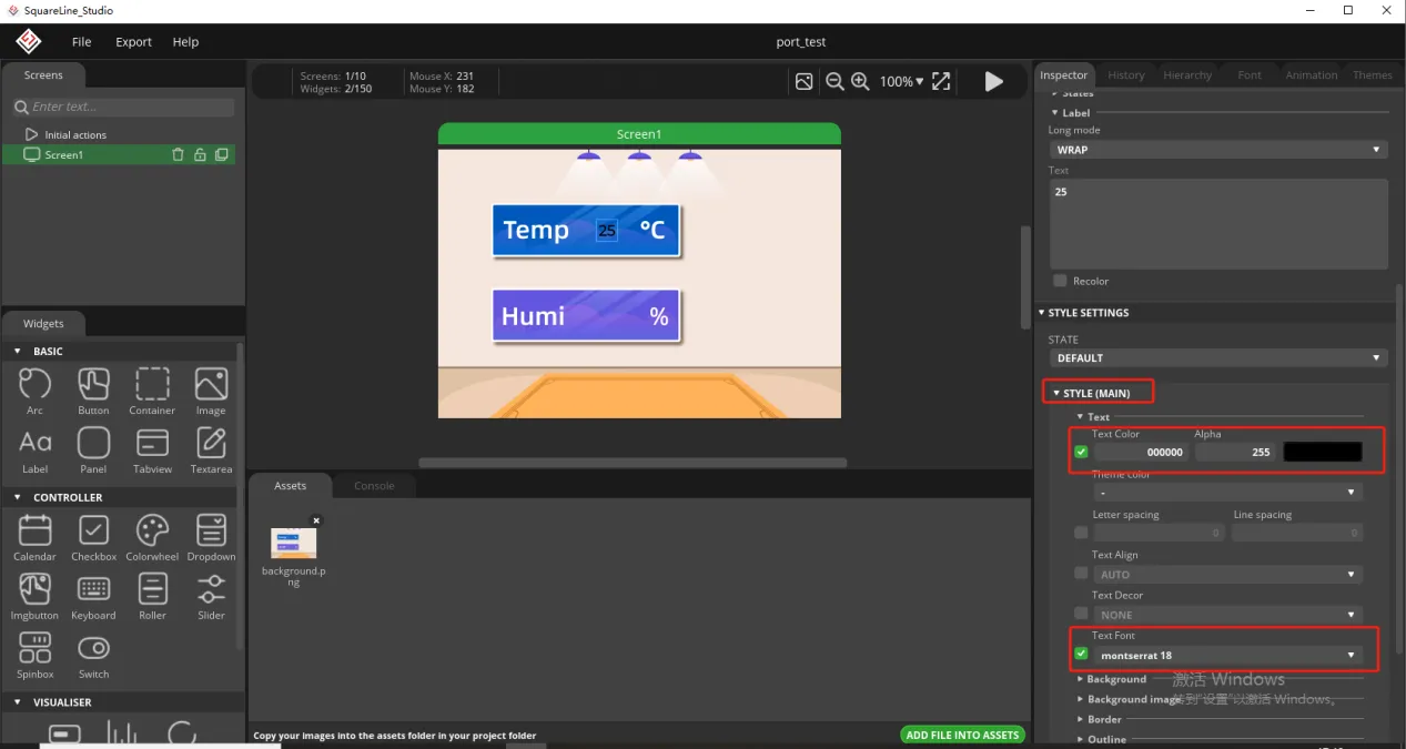
Of course, you can also set the font color and font size here
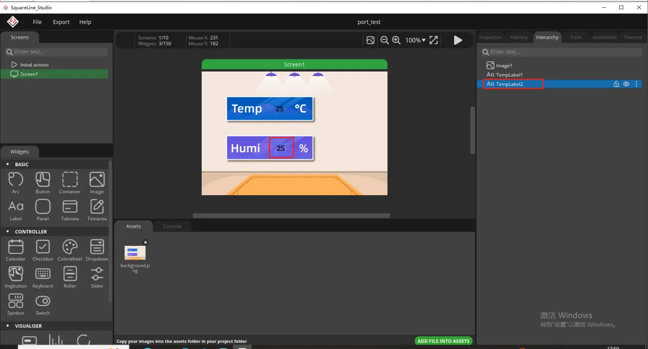
Copy the label just made and display the humidity value
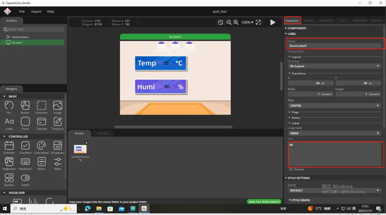
Follow the above steps to modify the humidity label
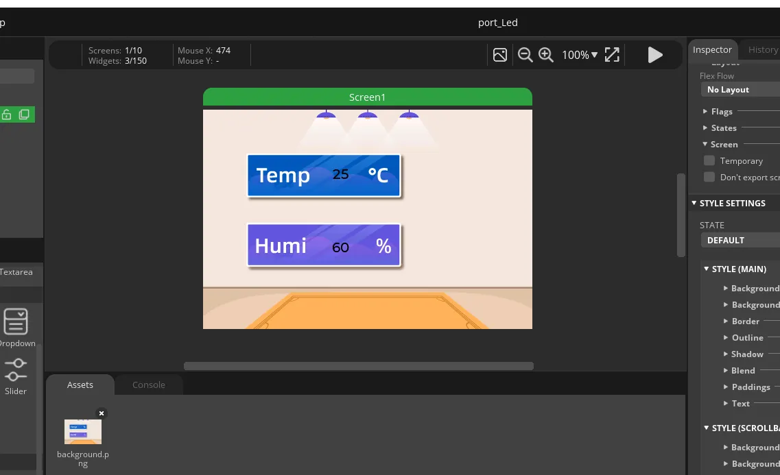
In this way, the display of temperature and humidity is completed.
So, the UI interface we need is completed.
Export the designed UI interface file
Go to the folder path where you selected to output the UI file.

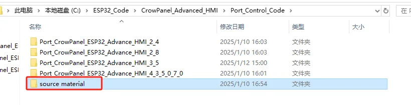
Download the files for lesson 4 from https://drive.google.com/drive/folders/1hEXyH14QeDgVdENxUfiYBQVCTbMbI6v9 and extract them, as shown below:
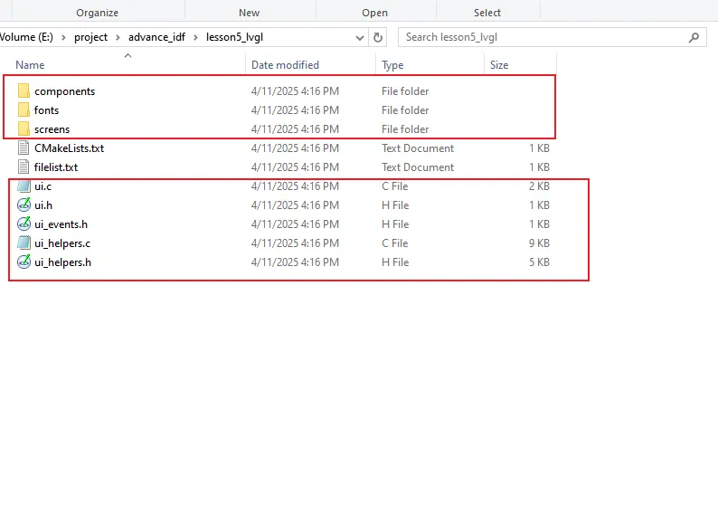
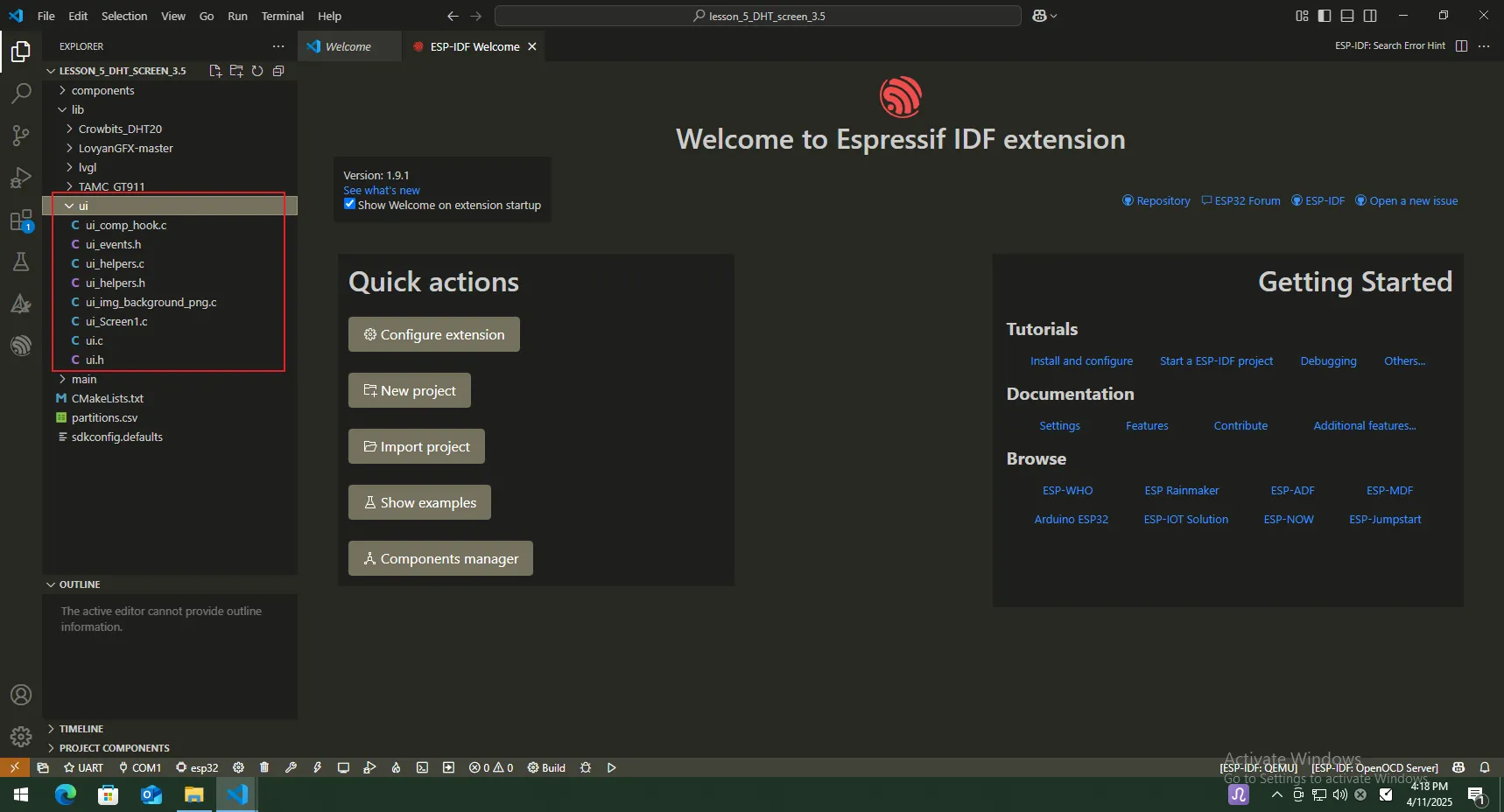
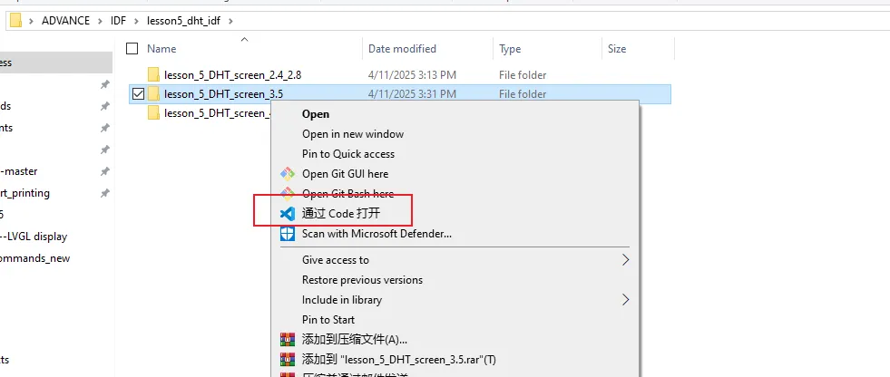
Then use VSCode to open the IDF project folder. Copy the generated .h and .c files into the corresponding folders of the project. (Here, I will use the code for the 3.5-inch version as an example.)
3 Code Explanation
Introduce several key points in the code
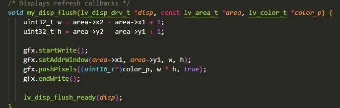
Screen refresh callback function
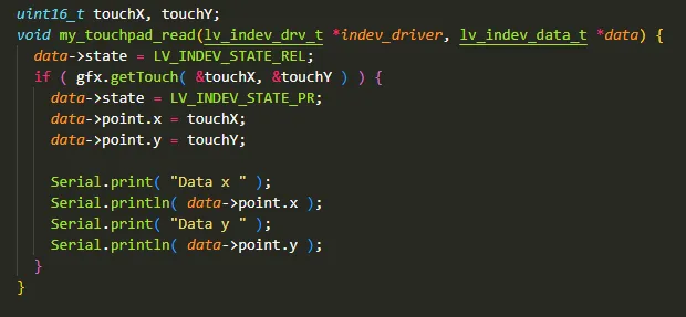
Touch coordinate reading function
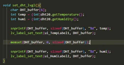
Function for Displaying Data of DHT20 Temperature Sensor
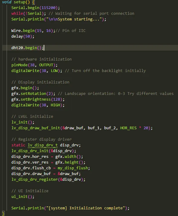
Initialization function, which initializes each functional module.
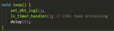
Refresh the screen regularly.
4 Hardware connection
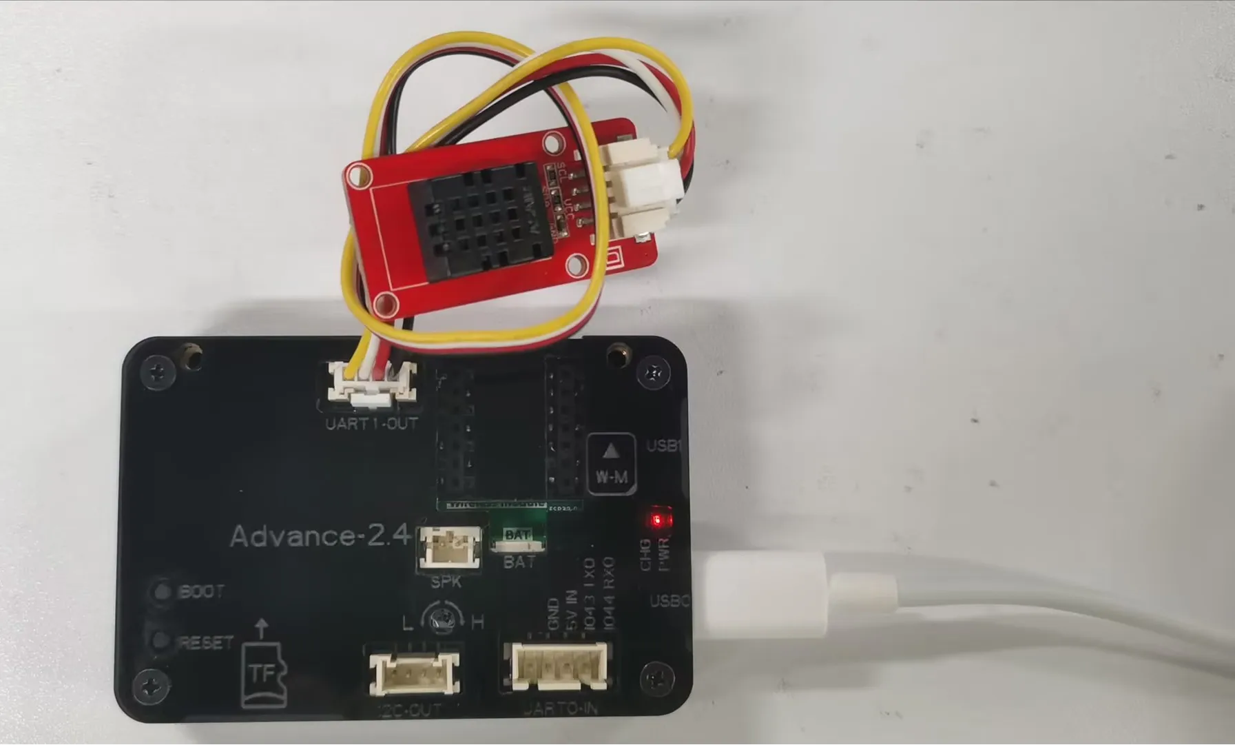
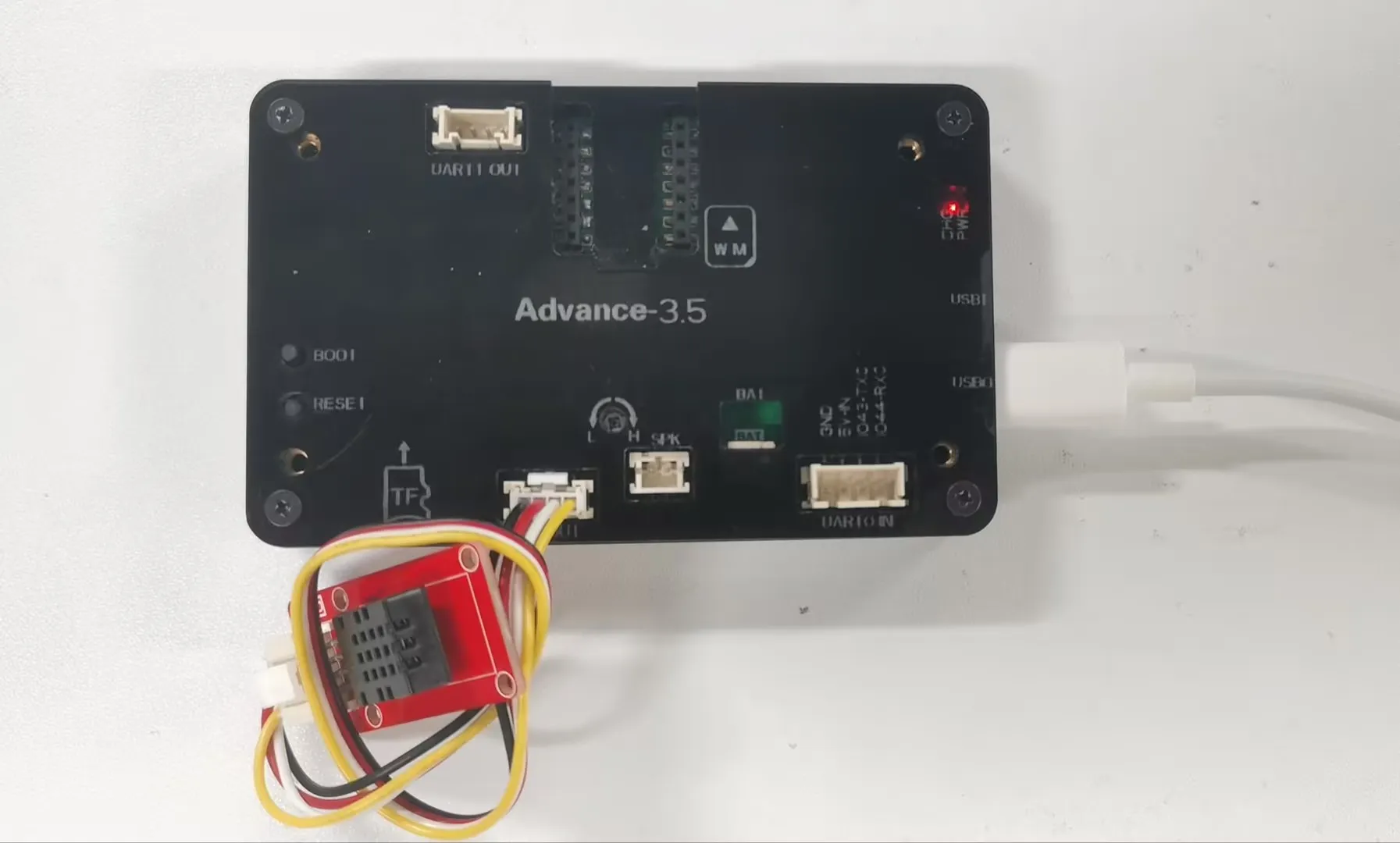
Connect the temperature sensor to the development board and power on the development board.
Note: For the 2.4-inch and 2.8-inch development boards, connect the temperature sensor to UART1-OUT. For other sizes, connect it to I2C-OUT.
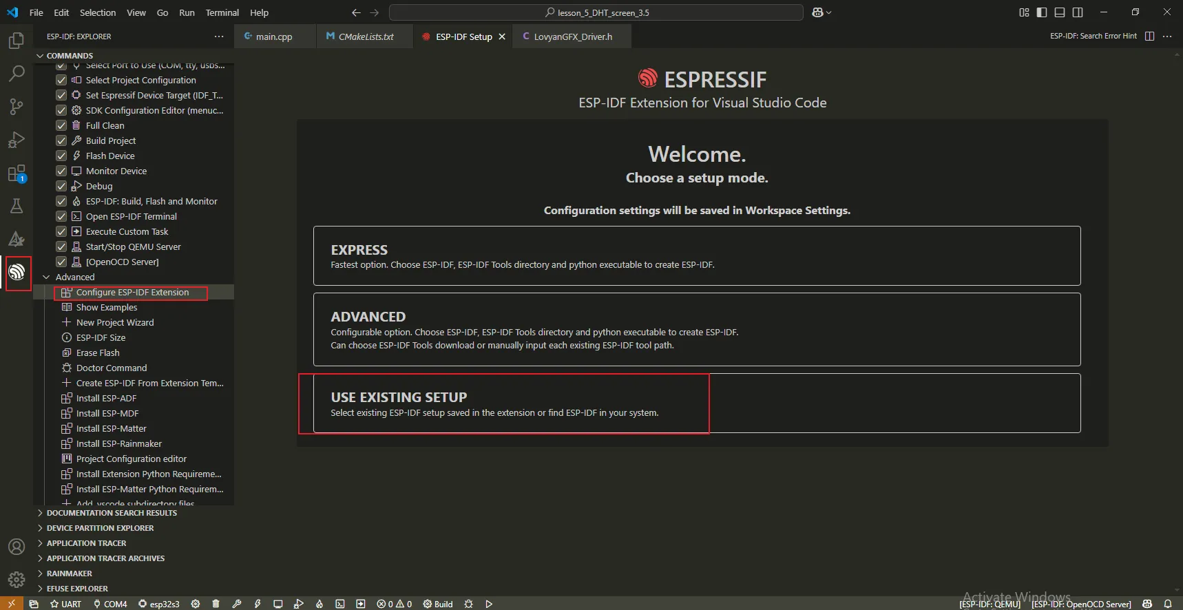
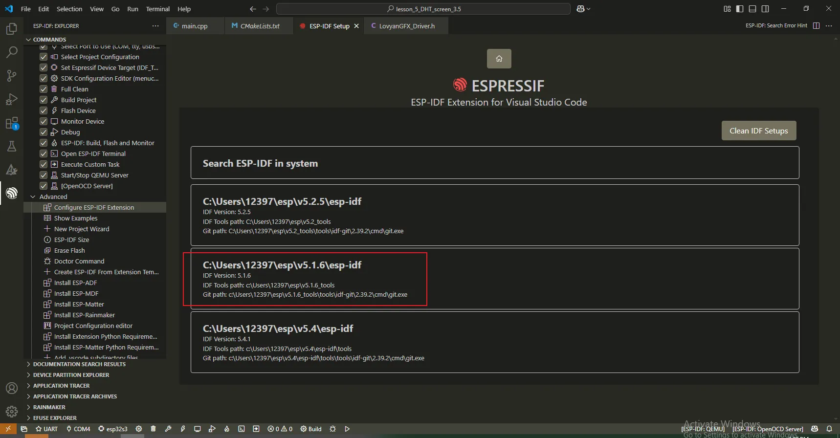
Select version idf v5.1.6. (Note: If you have previously installed other versions of IDF, you need to install version v5.1.6 first and then make the selection.)
Select the COM port to which the development board is connected and the model of the development board.
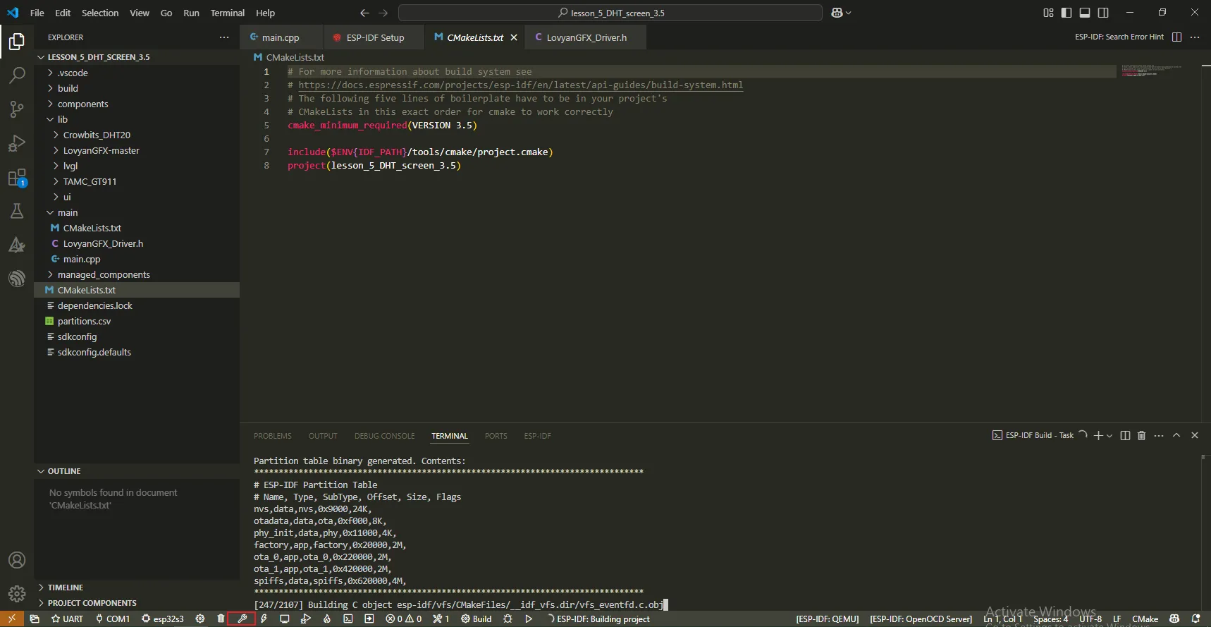
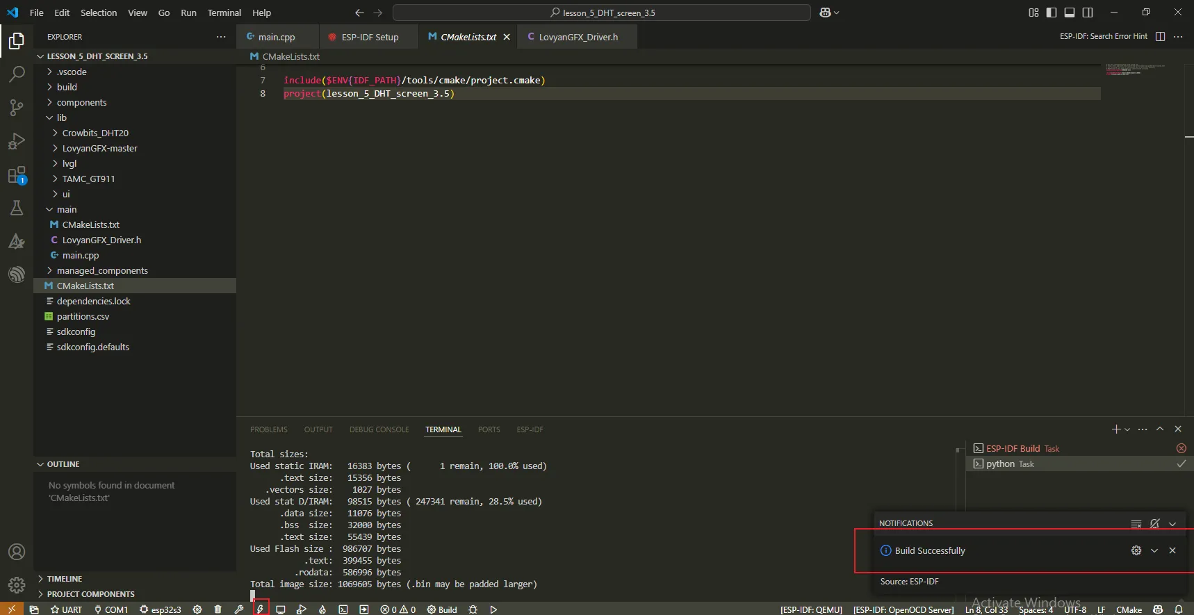
Click the "Compile" button and wait for the compilation to finish.

Click the "Flash" button after the compilation is completed.
Wait for the flashing process to complete.
You can observe the current temperature and humidity on the screen.