ESP Terminal SPI 3.5-inch Display Arduino Tutorial
Overview
This tutorial introduces how to configure the Arduino programming environment and how to set up the board.
The tutorial examples include the lvgl demo example (When you first received it, the demo it demonstrated after you powered it up), and how to connect the esp terminal to some sensors/modules.
Development environment configuration
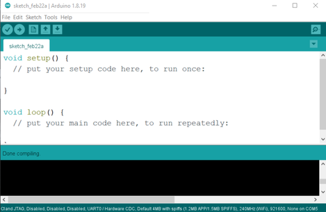
- 1.Please go to the official website https://www.arduino.cc/ to download the Arduino IDE, click the start icon: open as shown in the figure:
- 2.Download the libraries provided by Elecrow. Copy them to the library folder in the Arduino installation directory.
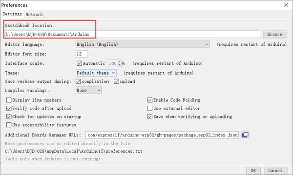
If you don't know the path of Arduino library directory, you can open Arduino IDE→Files→Preferences:
- Add the ESP32 S3 URL as follows:
https://raw.githubusercontent.com/espressif/arduino-esp32/gh-pages/package_esp32_index.json
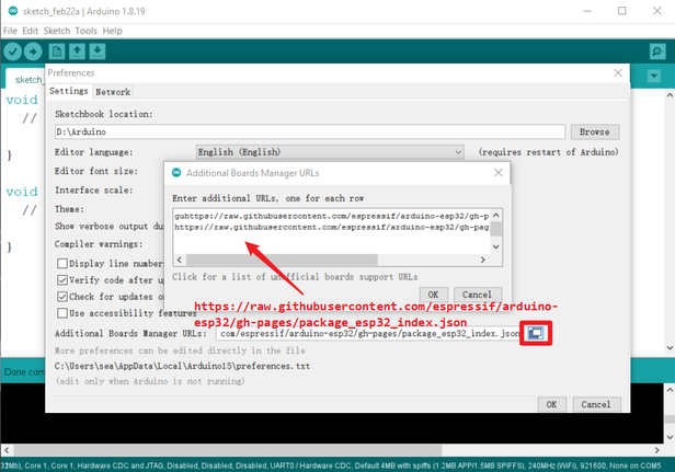
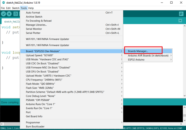
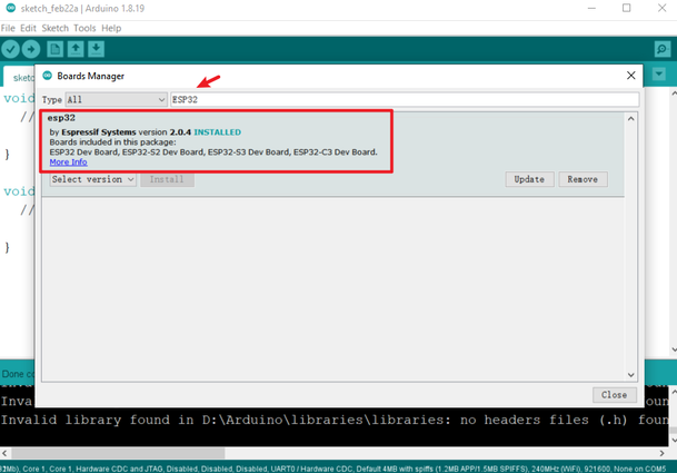
- The tool automatically downloads and updates the corresponding model, check the steps as shown in the figure:
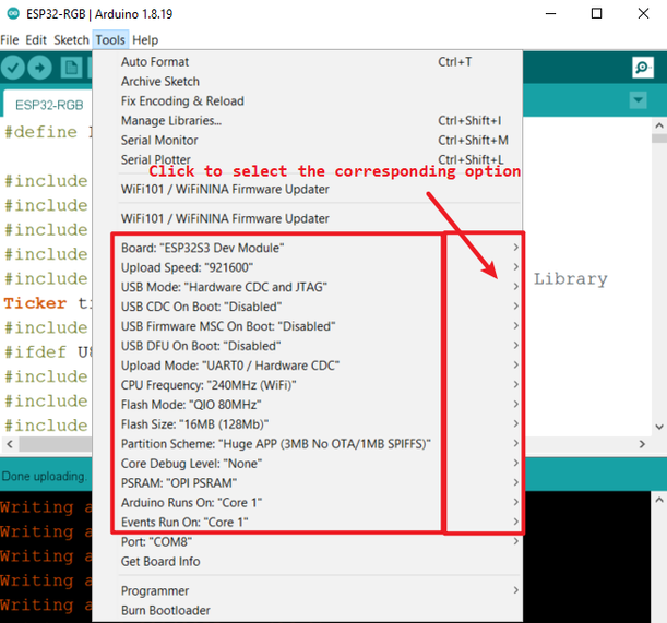
Board settings
- Set as shown
- warn:
If the CH340G driver is not installed on your PC, please install the CH340G driver first, or switch the SWITCH switch to the USB position and connect it with a USB cable.
Download process
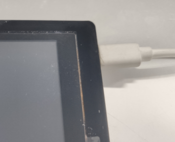
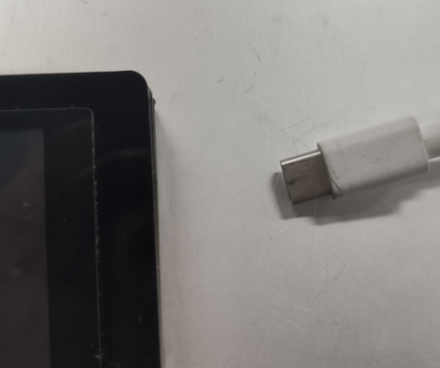
- 1.Connect the motherboard and computer through a USB to type-c data cable;
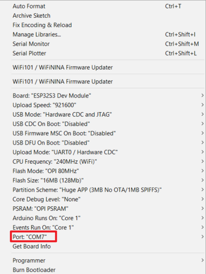
- 2.Click on the tool on the arduino software and select the corresponding serial port number;
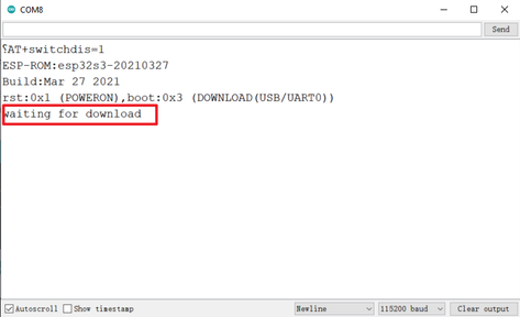
- 3.Click to open the serial port assistant, then click the boot button on the motherboard, and then press the reset button until the serial port assistant displays "waiting for download".
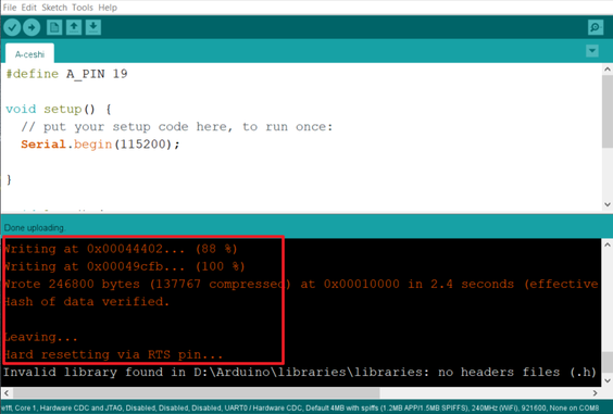
- 4.Click "upload" to upload the program to the ESP32 motherboard

- Until the prompt upload is successful, as shown in the figure:
- 5.Press the "Reset" button and the code will run on the display.
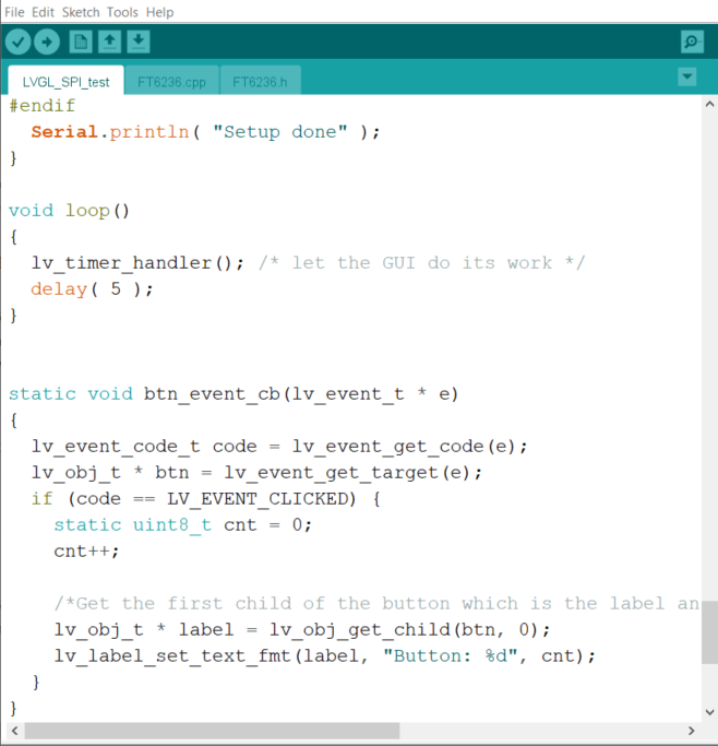
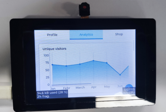
LVGL Widgets Demo
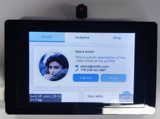
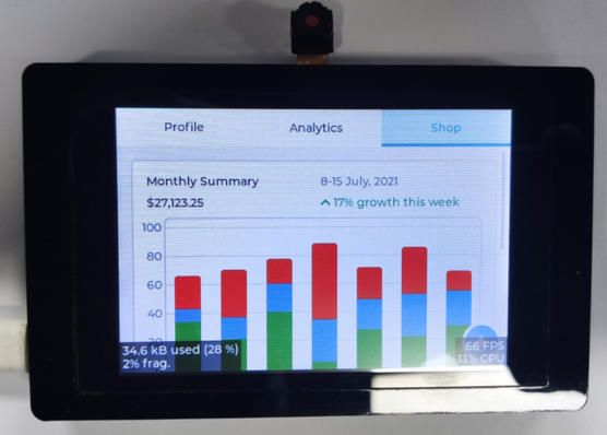
- After downloading the LVGL_SPI_test.INO code, restart the screen, and you can see various function module icons.
- Running result:
Connect With Crowtails
Hardware Preparation
| ESP Terminal SPI | Crowtail-OLED | Crowtail-LED | Crowtail- Light Sensor | USB-A(or USB-C) to USB-C cable | 2* 4-Pin HY2.0 Cables |
|---|---|---|---|---|---|
 ]{ loading=lazy } ]{ loading=lazy } | 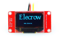 | 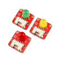 | 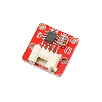 | 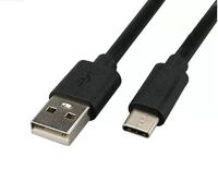 | 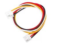 |
| Get one now | Get one now | Get one now | Get one now | Get one now | Get one now |
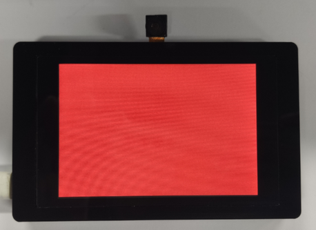
- Example 1 Display the screen color of the LCD
- After the A-LCD.INO code is downloaded, the restart screen will be in a different color.
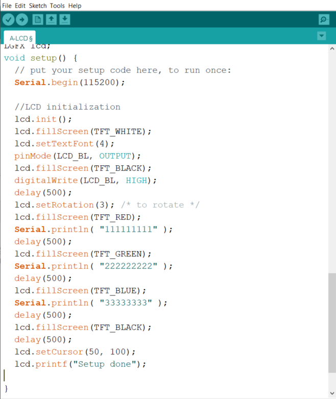
- Running result:
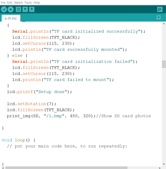
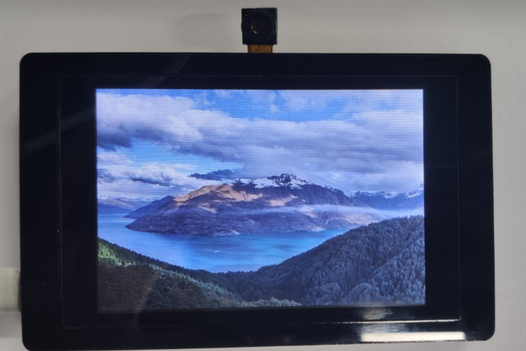
- Example 2 Display pictures and read TF card pictures
- After the A-TF-PIC.INO code is downloaded, the restart screen will display the picture screen.
- Running result:
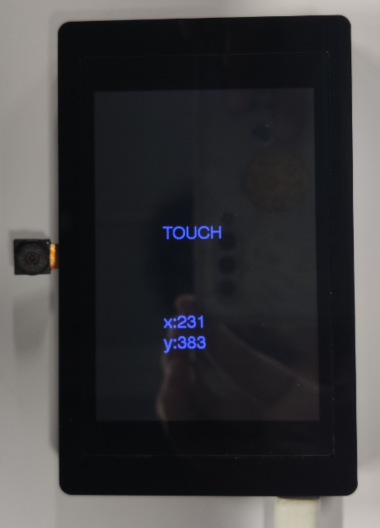
- Example 3 touch function display
- After the A-TOUCH.INO code is downloaded, the restart screen will automatically display the XY coordinates of the touch, and the corresponding X Y values will be displayed when touching different positions
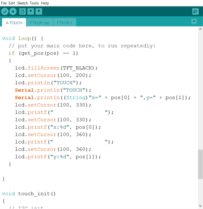
- Running result:
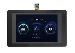
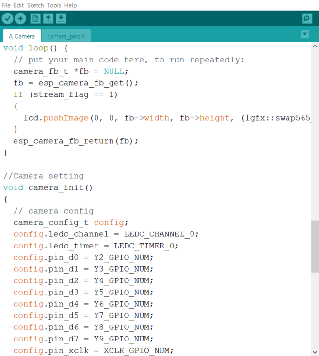
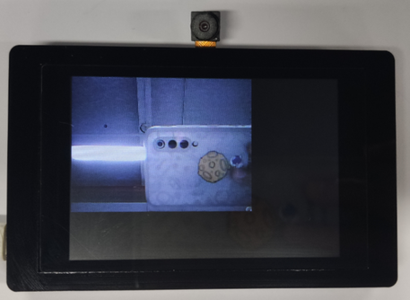
- Example 4 camera function display
- After downloading the A-Camera.INO code, restart the screen and enter the camera screen.
- Running result:
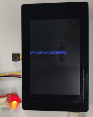
- Example 5 connect GPIO port, I2C port, UART port
- After downloading the A-A_D_PORT.INO code, restart the screen, automatically light up the LED on the GPIO port, and read the analog value from the analog port.
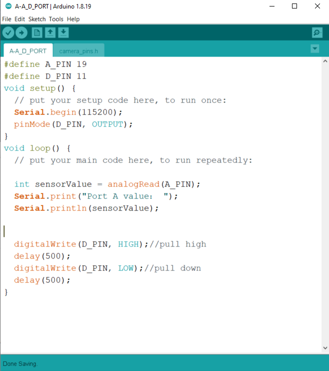
- Running result:
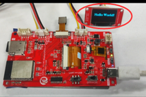
- Example 6 Connect I2C port
- After downloading the A-IIC.INO code, restart the screen, and the I2C port peripheral will display "ELECROW".
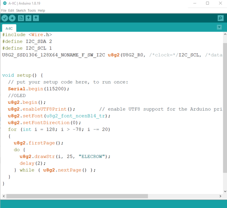
- Running result:
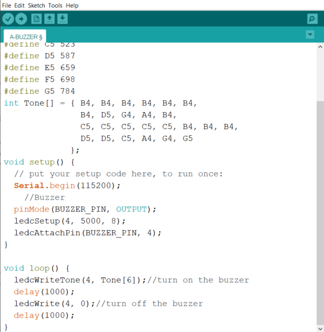
- Example 7 Buzzer function
- After the A-BUZZER.INO code is downloaded, restart the screen and the buzzer will sound.
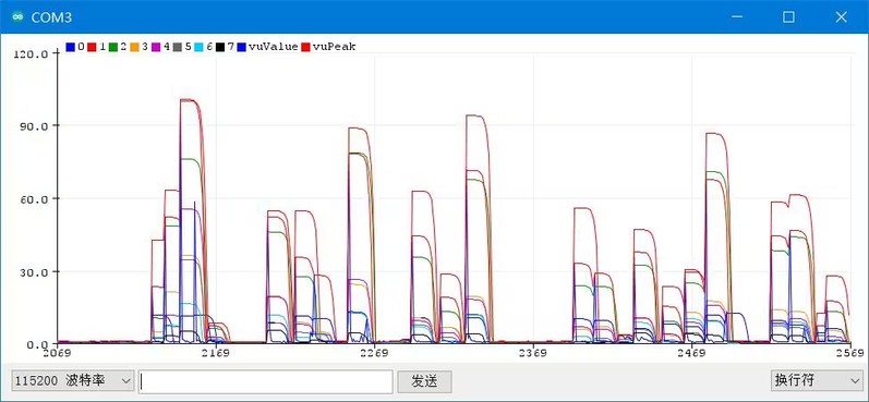
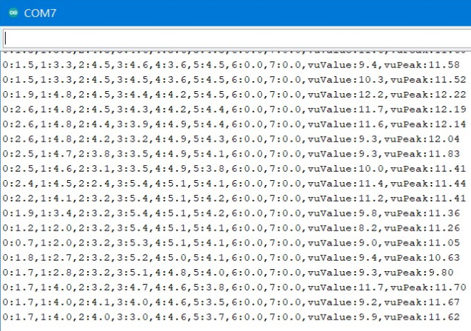
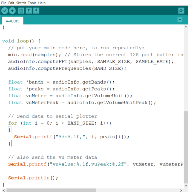
- Example 8 Microphone
- After downloading the A_AUDIO.INO code, restart the screen.
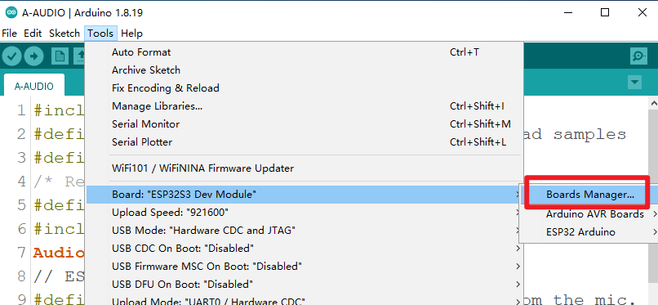
- Note: Here you need to choose esp32 2.0.3 version.
①Select Boards Manager in Tools.
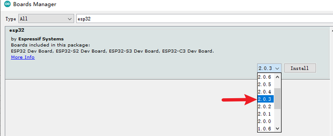
②Select version 2.0.3.
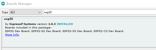
③Complete as follows.
- After burning, connect the arduino serial port tool, and select "serial plotter" in the tool drop-down menu.
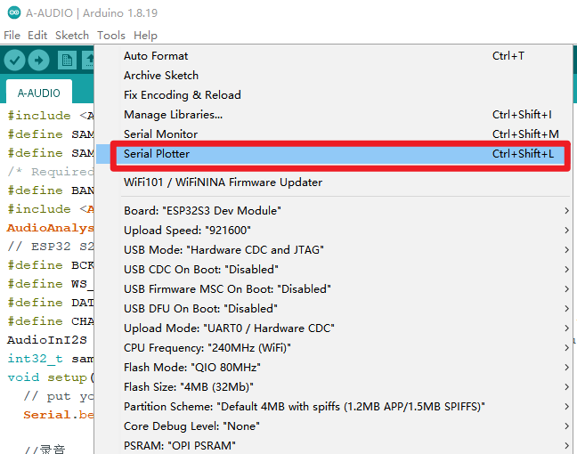
- Running result: