Lesson 10 Developing Thread Wireless Mesh Network Technology for CrowPanel Advance AI Display
1. Environment Configuration:
This project is developed and tested with ESP-IDF v5.5.4. If you have not installed this version yet, please refer to Lesson 1 of this ESP-IDF tutorial series to set up the required software environment before proceeding with the following steps.
Software Environment Installation Guide:
https://www.elecrow.com/wiki/IDF_01_Install_Software_Environment_V13.html
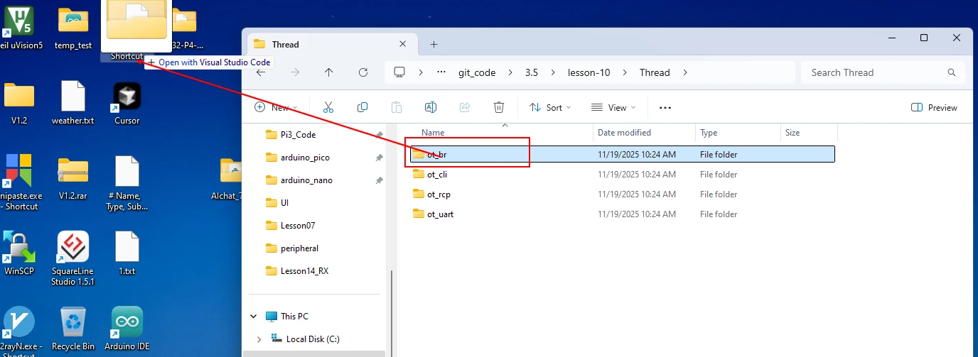
Click the link below to download the Thread communication code:
You can drag your project into VS-Code to open the code.
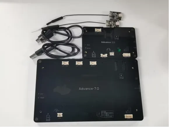
2. Hardware Composition:
(1) Two "CrowPanel Advance HMI AI Display"
(2) Two wireless modules (ESP32-H2 or ESP32-C6)
(3) Two Type-C cables
In this tutorial, a 7.0-inch display paired with a wireless module (ESP32-H2 or ESP32-C6) is used as the Thread Border Router.
while a 3.5-inch display paired with another wireless module (ESP32-H2 or ESP32-C6) is used as the Thread End Device.
The project code provided with this lesson is specifically designed for this hardware configuration.
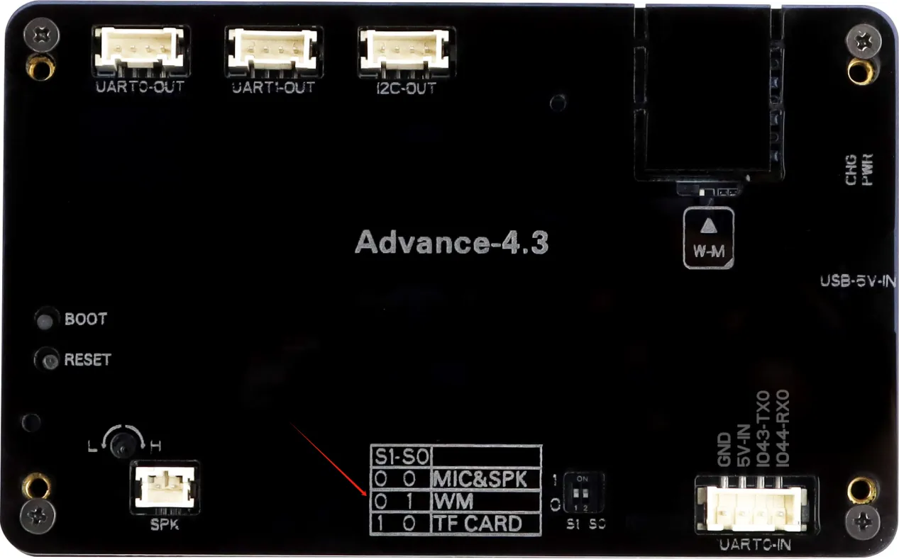
Note:
Before connecting the devices, set the Function Select Switch on the 7.0-inch, 5.0-inch, or 4.3-inch development board to "01 - Wireless Module Mode" to enable communication with the ESP32-H2 or ESP32-C6 wireless module.
3. Software Packages:
The project contains four firmware programs. Please flash each program to the corresponding device as shown below:
- ot_brt – Border Router Host firmware Flash this firmware to the CrowPanel Advance HMI AI Display (7.0-inch, 5.0-inch, or 4.3-inch).
- ot_rcp – Border Router RCP (Radio Co-Processor) firmware Flash this firmware to the ESP32-H2 or ESP32-C6 wireless module connected to the Border Router display.
- ot_uart – UART Forwarding firmware for the CLI Device Flash this firmware to the CrowPanel Advance HMI AI Display (3.5-inch, 2.8-inch, or 2.4-inch).
- ot_cli – OpenThread CLI Device firmware Flash this firmware to the ESP32-H2 or ESP32-C6 wireless module connected to the CLI device display.
In summary, the display boards run either ot_brt or ot_uart, while the wireless modules (ESP32-H2/ESP32-C6) run either ot_rcp or ot_cli, depending on whether they are being used as the Border Router or the CLI Device.
Recommended Firmware Pairings:
- ot_brt should be used together with ot_rcp to form a complete Thread Border Router system.
- ot_uart should be used together with ot_cli to form a complete Thread CLI Device system.
Make sure that each firmware pair is flashed to the corresponding display board and wireless module before testing network communication.
ot_brt:
(1) As shown in Figure 1, the host (ot_brt) is configured to communicate with the RCP side using a UART connection. The following shows the serial port configuration settings. The specific UART pins (IOs) should be selected according to the actual hardware setup. In addition, parameters such as the baud rate must be kept consistent with the configuration defined on the RCP (ot_rcp) side to ensure proper communication.
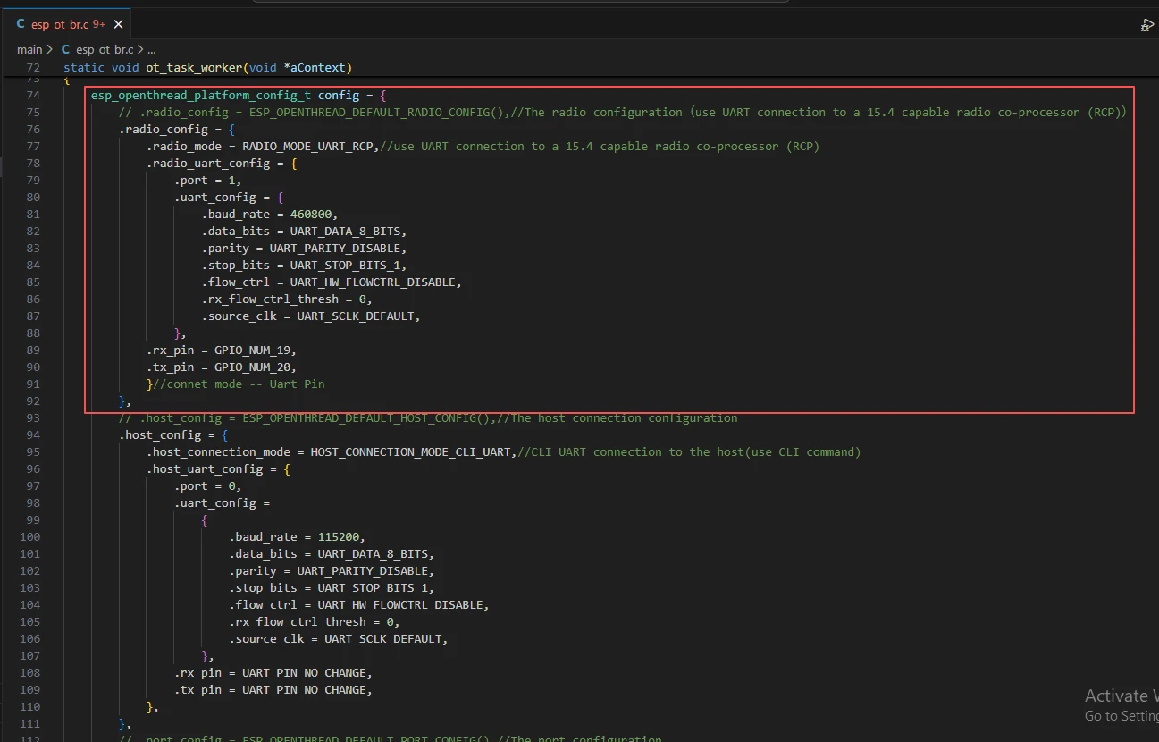
Figure 1
(2) As shown in Figure 2, the CLI is configured to communicate with the host using a UART connection. The specific UART ports and IO assignments should be selected according to the actual hardware configuration. This setup allows convenient configuration and management of the Thread network through CLI commands in later steps.
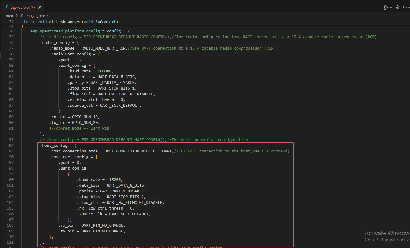
Figure 2
(3) The Border Router Wi-Fi can operate in automatic startup mode using CONFIG_OPENTHREAD_BR_AUTO_START. When enabled, the system will automatically retrieve the SSID and password stored in NVS or configured via Kconfig and use them for connection.
By default, this automatic mode is disabled. In this case, the SSID and password must be manually configured using CLI commands.
ot_rcp:
For ot_rcp, the following explanation is provided:
As shown in Figure 3, configure the radio operating mode. When the RCP is connected to the host device, it should be set to UART mode. The specific UART ports and GPIO assignments should be configured according to the actual hardware setup. In addition, communication parameters such as the baud rate must match those configured on the host side to ensure stable and reliable communication.
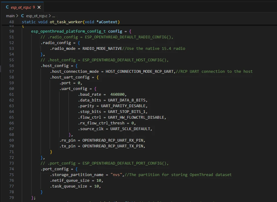
Figure 3
ot_cli:
As shown in Figure 4, configure the radio usage mode. When the CLI is connected to the host, it should operate in UART mode. The specific UART ports and GPIO pins should be selected based on the actual hardware configuration.
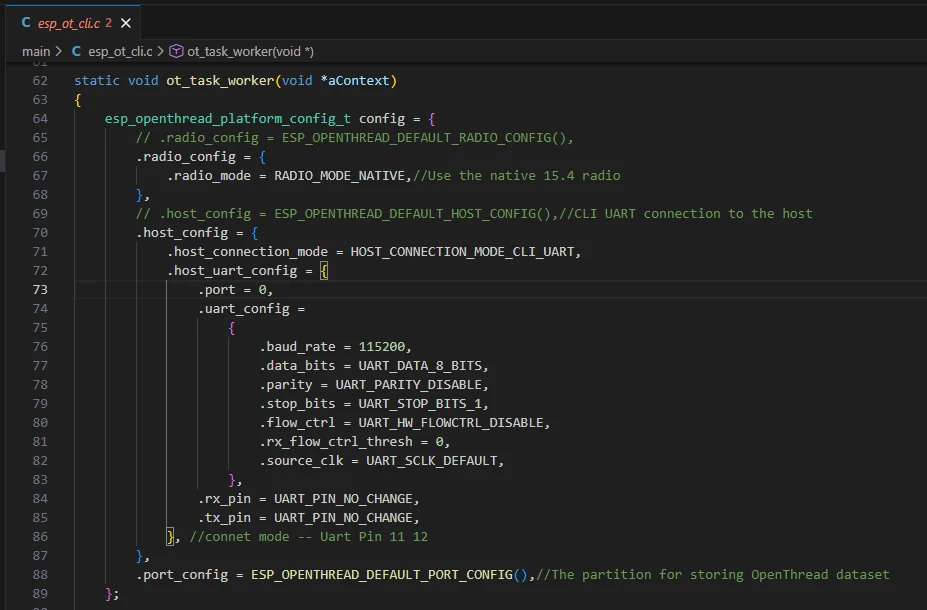
Figure 4
ot_uart:
As shown in Figure 5, configure the serial port forwarding settings in sdkconfig. In this device, GPIO1 of the ESP32-S3 is assigned as the CLI UART TX pin, and GPIO2 is assigned as the CLI UART RX pin.
This is because the pin mapping differs depending on the display size. For the 7.0-inch, 5.0-inch, and 4.3-inch models, the corresponding pins are GPIO19 and GPIO20. For the 3.5-inch, 2.8-inch, and 2.4-inch models, the corresponding pins are GPIO1 and GPIO2.
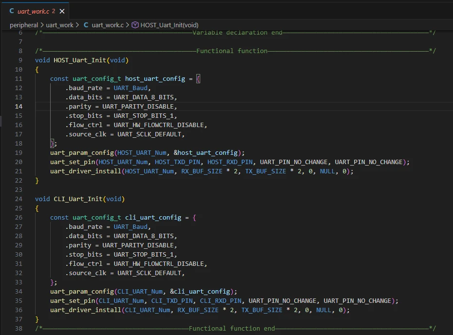
Figure 5
4. Specific operation steps
Step 1: Flash the ot_brt code into a 7.0-inch display screen and the ot_rcp code into a wireless module (ESP32-H2 or ESP32-C6), and combine them to form a border router. (Note: If the RCP side cannot be recognized, the code on the host side will restart continuously.)
Connect the devices to the computer respectively.
- Flash the ot_brt code into the 7.0-inch display screen.
After switching to version ESP-IDF_V5.5.4, perform the following operations to flash the code onto the development board.
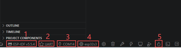
For the development boards of the Advance series, the main controller is ESP32-S3.
① Select the previously downloaded ESP-IDF V5.5.4
② Select the UART programming method
③ Select the serial port you connected to your computer
④ Select the main controller ESP32-S3
⑤ Clicking this button will automatically complete the full workflow: build the project, flash the firmware, and open the serial monitor in one step.
- Flash the ot_rcp code into the wireless module (ESP32-H2 or ESP32-C6).
After switching to version ESP-IDF_V5.5.4, perform the following operations to flash the code onto the development board.
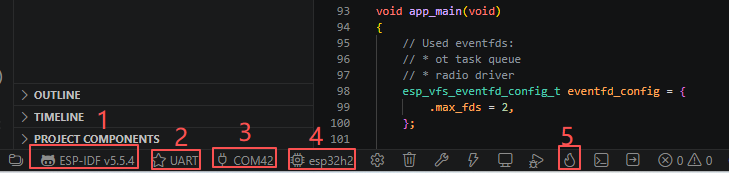
For ESP32-C6 / ESP32-H2
① Select the previously downloaded ESP-IDF V5.5.4
② Select the UART programming method
③ Select the serial port you connected to your computer
④ Select the main controller ESP32-H2
⑤ Clicking this button will automatically complete the full workflow: build the project, flash the firmware, and open the serial monitor in one step.
Note:
For ESP32-C6 / ESP32-H2, you need to enter programming mode before flashing.
Press and hold the BOOT button, then briefly press the RESET button while continuing to hold BOOT. This will put the chip into download (programming) mode. After that, release the buttons and click the “⑤” button to start flashing the firmware.
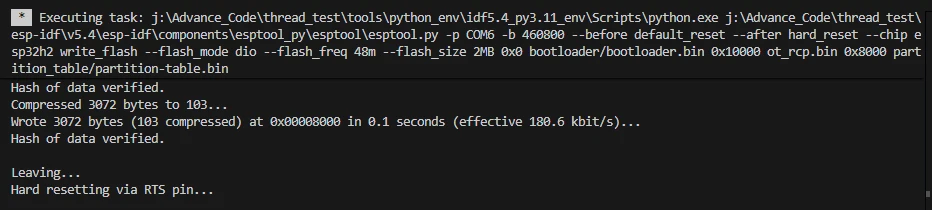
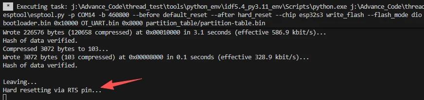
The interface after the burning is completed.
Step 2: Flash the ot_uart code into the 3.5-inch display screen, and flash the ot_cli code into another wireless module (ESP32-H2 or ESP32-C6) to serve as a sub-device or router.
Connect the devices to the computer respectively.
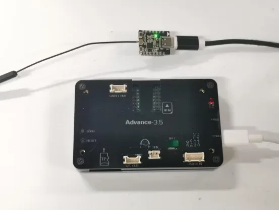
- Flash the ot_uart code into the 3.5-inch display screen.
After switching to the ESP-IDF_V5.5.4 version, perform the following operations to flash the code onto the development board.
For the development boards of the Advance series, the main controller is ESP32-S3.
① Select the previously downloaded ESP-IDF V5.5.4
② Select the UART programming method
③ Select the serial port you connected to your computer
④ Select the main controller ESP32-S3
⑤ Clicking this button will automatically complete the full workflow: build the project, flash the firmware, and open the serial monitor in one step.
- Flash the ot_cli code into the wireless module (ESP32-H2 or ESP32-C6).
After switching to the ESP-IDF V5.5.4 version, perform the following operations to flash the code onto the development board.
For ESP32-C6 / ESP32-H2
① Select the previously downloaded ESP-IDF V5.5.4
② Select the UART programming method
③ Select the serial port you connected to your computer
④ Select the main controller ESP32-H2
⑤ Clicking this button will automatically complete the full workflow: build the project, flash the firmware, and open the serial monitor in one step.
Note:
For ESP32-C6 / ESP32-H2, you need to enter programming mode before flashing.
Press and hold the BOOT button, then briefly press the RESET button while continuing to hold BOOT. This will put the chip into download (programming) mode. After that, release the buttons and click the “⑤” button to start flashing the firmware.
The interface after the burning is completed.
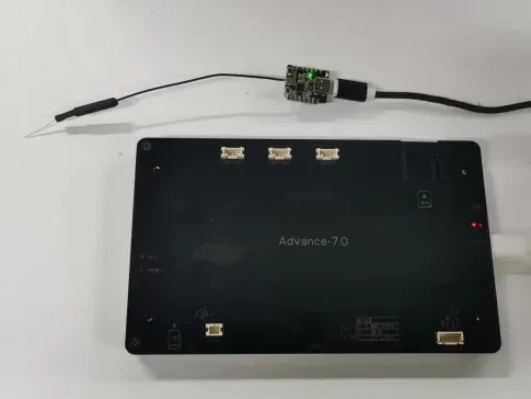
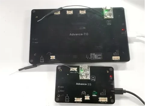
Step 3: Combine the border router and the sub-device respectively, and connect them to the computer, as shown in the following figure.
Step 4: Set up the border router
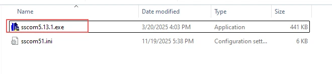
Open the serial port assistant we provide. It will be able to assist you very well in using it. (Of course, if you have a better serial port assistant, you can also use that.)
Click the link below to download the serial port assistant we provide for your use.
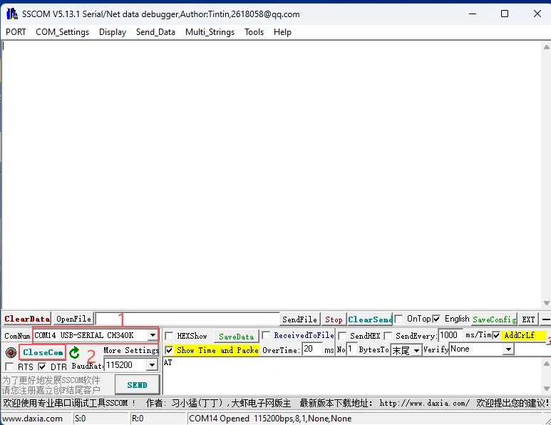
Double-click to open this serial port assistant
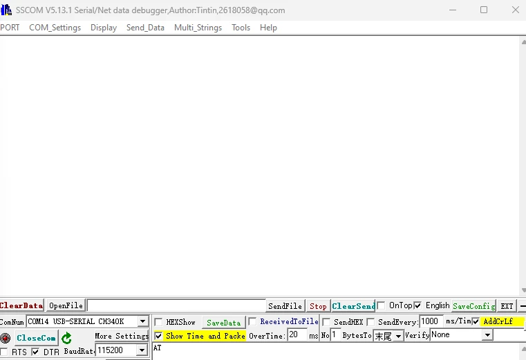
Select the serial port corresponding to your size of product, and then open the serial port.
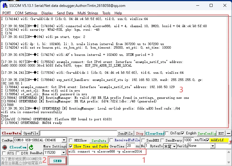
Connect the 7.0-inch development board to the computer via UART, and transmit the command string "wifi connect -s xxx -p xxx" to configure the Wi-Fi connection.
Replace the above xxx with the WiFi account and password you are using.
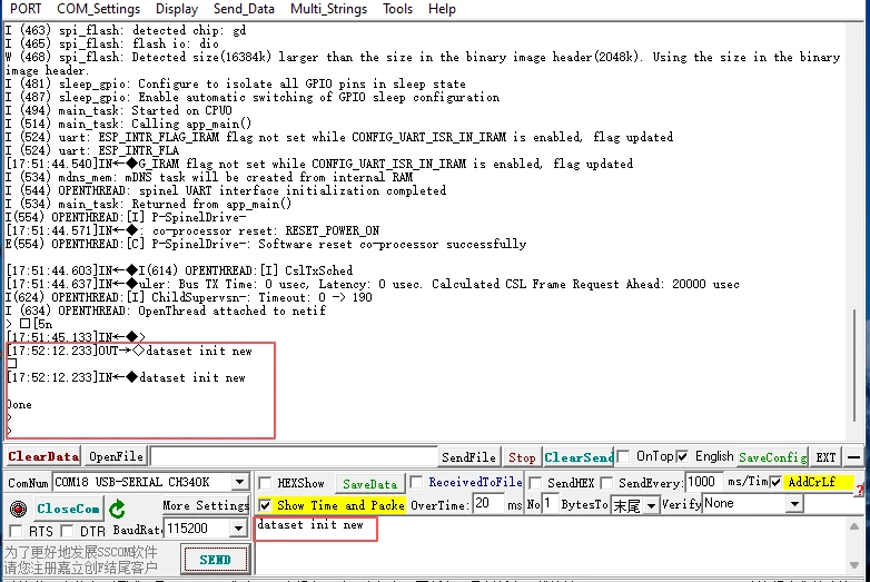
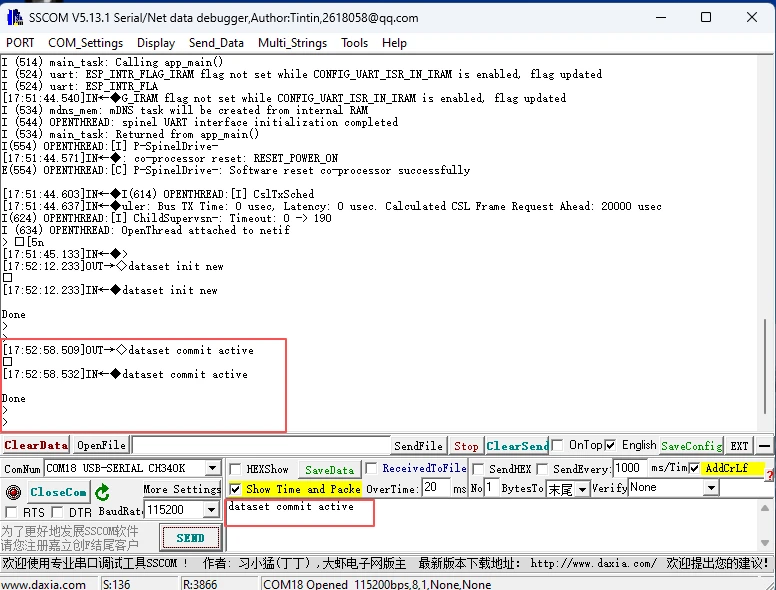
Sequentially send the following command strings to initialize and bring up a Thread network:
"dataset init new" → "dataset commit active" → "ifconfig up" → "thread start".
- dataset init new
This command creates a new Thread network dataset with default parameters, preparing a fresh configuration for network setup.
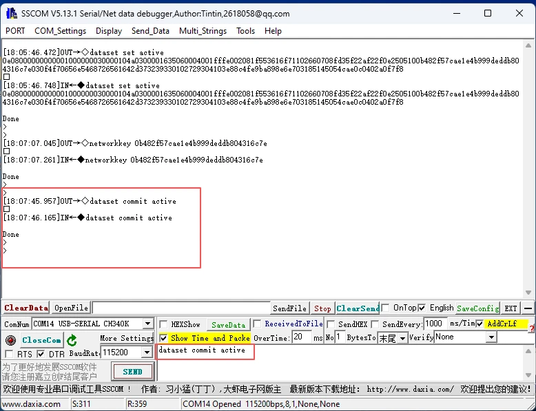
- dataset commit active
This command commits the newly created dataset as the active configuration, making it the current operational network settings.
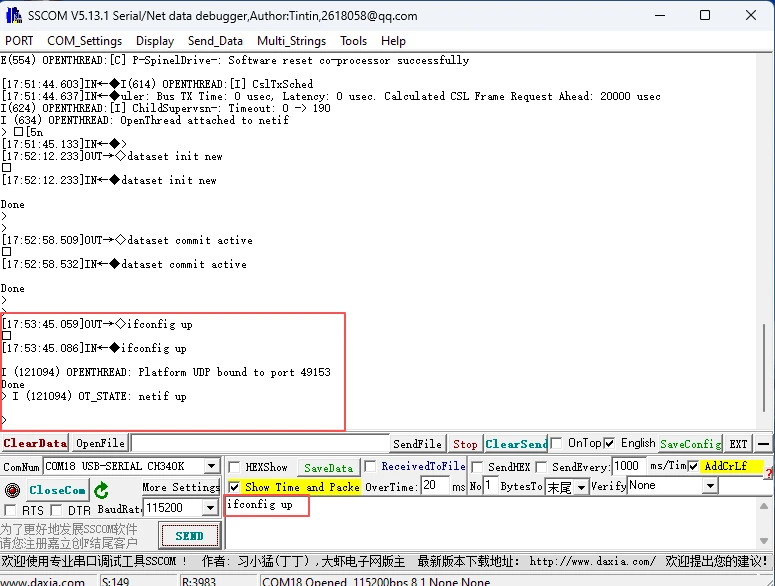
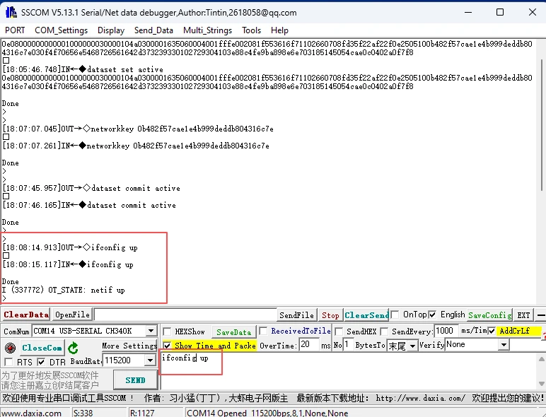
- ifconfig up
This command brings up the network interface, enabling the device’s networking stack to become active.
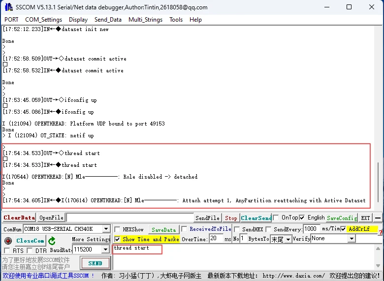
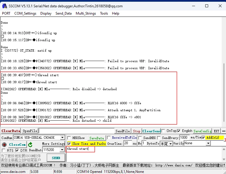
- thread start
This command starts the Thread protocol stack, allowing the device to join or form a Thread network.
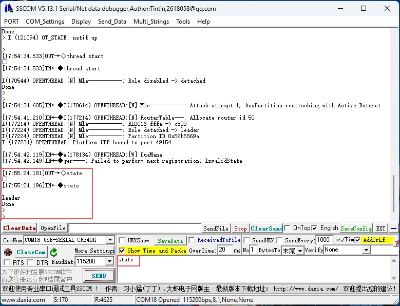
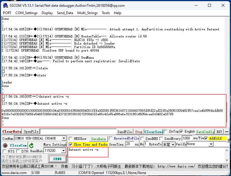
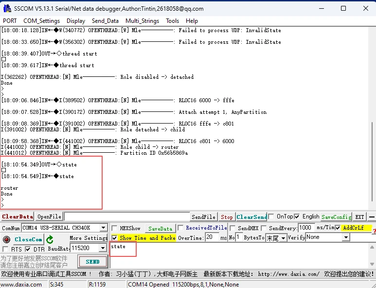
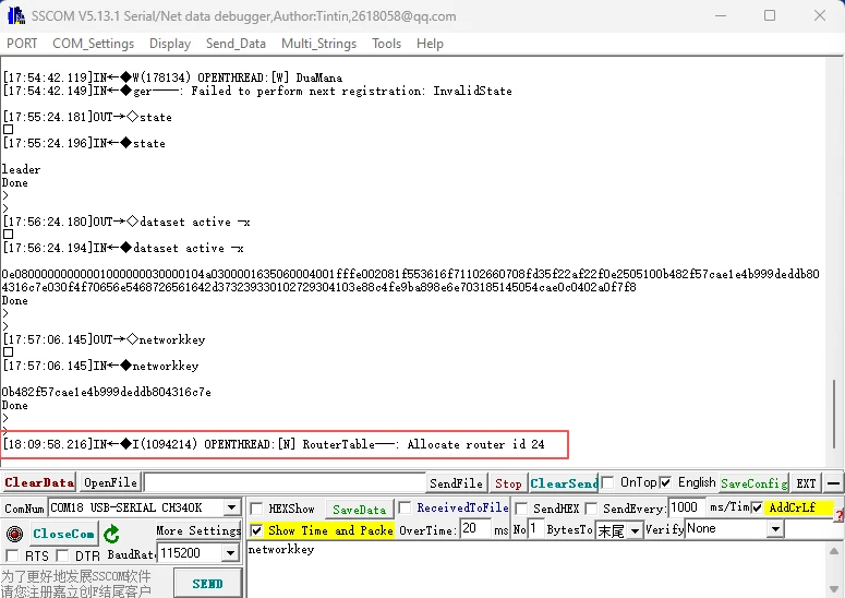
The border router exists as the leader in the Thread network, and the command string "state" can be used to check its status.
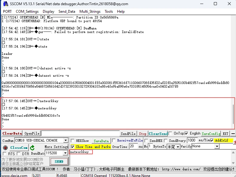
Use the command string "dataset active -x" to obtain the Thread network dataset or "networkkey" to obtain the network key, so that other CLI devices can join the Thread network conveniently. (Choose one of them.)
Step 5: Set up the child device or router:
Connect the 3.5-inch development board to the computer via UART and open the serial port assistant.
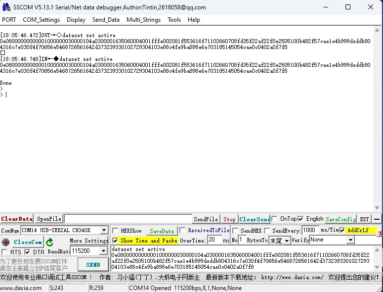
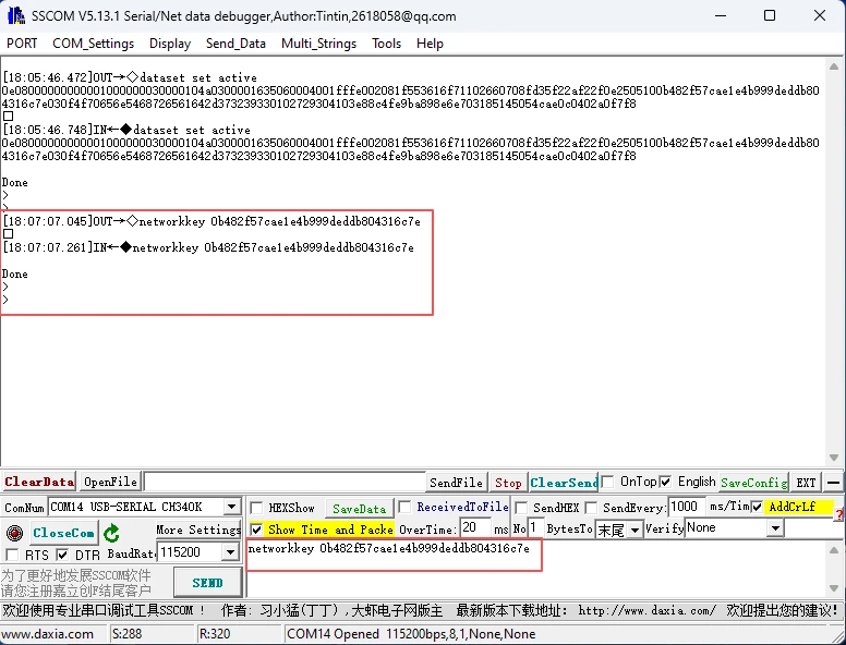
Submit the network dataset using the command "dataset set active xxx" or the network key using the command "dataset networkkey xxx". (Choose one of them.)
The xxx mentioned here was obtained on the 7-inch device just now. You can simply copy it from there.
Set the active network data on the CLI device using the command "dataset commit active".
Use "ifconfig up" and "thread start" in sequence to form a Thread network.
The CLI device acts as a child device or a router in the Thread network.
After the thread network settings are completed, you can input "state" to check the current status of the device, which indicates the current role it is in.
At this point, it is a successful state for the distribution network. That is to say, both parties have been properly matched. Then, if you observe the serial port information on the 7-inch end, you can see the relevant information indicating successful network connection, and an ID number has been randomly assigned to the 3.5-inch end.
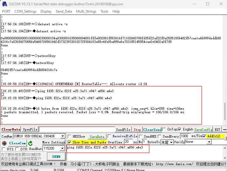
Of course, you can also check it out. On the 7-inch device, ping the 3.5-inch device to see if you can get a response.
As shown in the picture, this indicates a successful ping.
Step 6: Send data from the leader side to the child side:
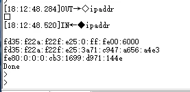
Obtain the IPv6 address of the receiving child side; the child side can send the CLI command "ipaddr" via UART, which can output the IPv6 address of each board.
In the picture below, just pick the longest one.
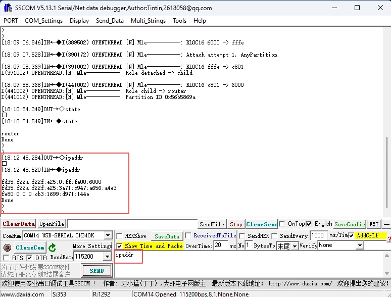
The information therein represents:
The first line "fd35:f22a:f22f:e25:0:ff:fe00:6000" is the unique local multicast address for the Thread network, used to send multicast data such as network instructions and configuration updates to all routers within the network;
The second line "fd35:f22a:f22f:e25:3a71:c947:a656:a4e3" is the unique local unicast address for the Thread device, serving as the core communication identifier for the device, enabling unicast communication between devices and cross-network data transmission (such as cloud reporting);
The third line "fe80::cb3:1699:d971:144e" is a link-local unicast address, used only for device initialization communication within the Thread network (such as neighbor discovery and access negotiation), and cannot be accessed across networks.
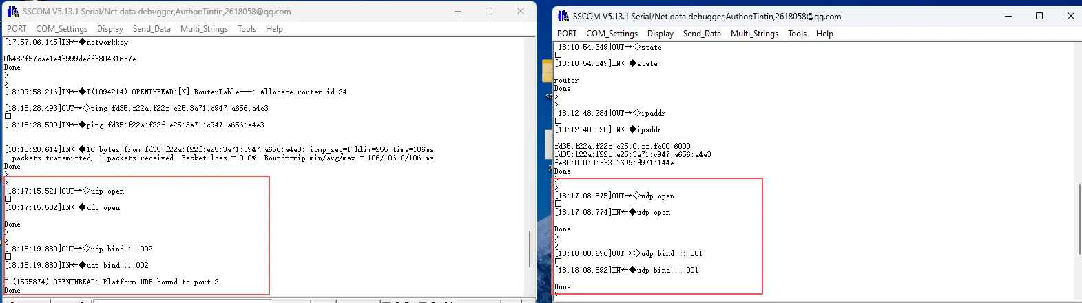
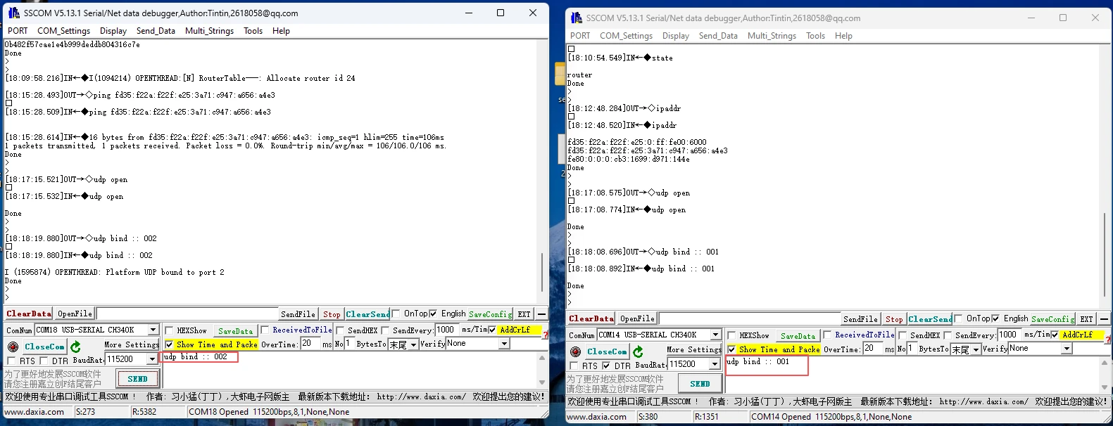
On the receiving child side, use the CLI command "udp open" to enable the UDP function, and use "udp bind :: xxxxx" to bind the port (here, the custom port number of the child side is set as 001).
-
(Both ends need to enable UDP, and both ends need to bind port numbers, and they should be set differently)
-
(Here, the 7-inch display on the left is bound to 002)
-
(Here, the 3.5-inch display on the right is bound to 001)
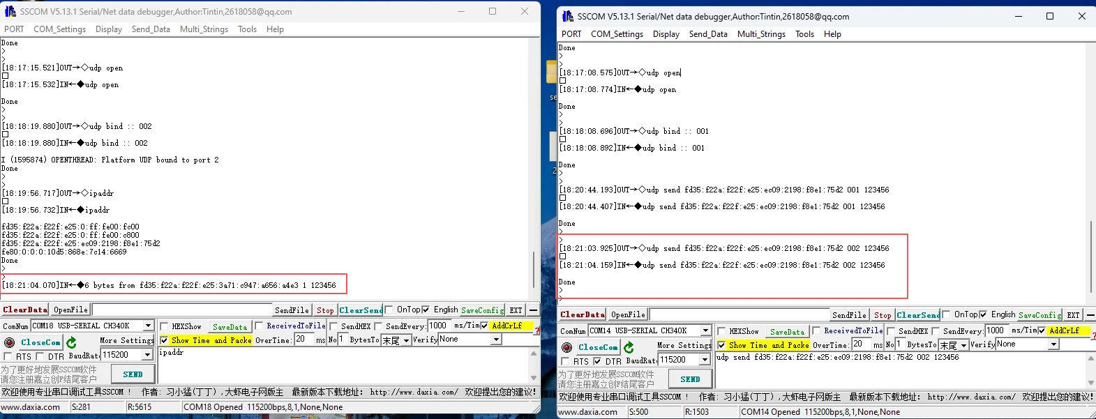
Then use the command "udp send xxx (the ML-EID address in the IPv6 address) xxx (port number) xxx (the content of the information to be sent)".
(Here, I first input the ipaddr to obtain the 7-inch IPv6 address, and then input the sending command on the 3.5-inch end. Send 123456 to the 7-inch device.)
You can see that the sending was successful!
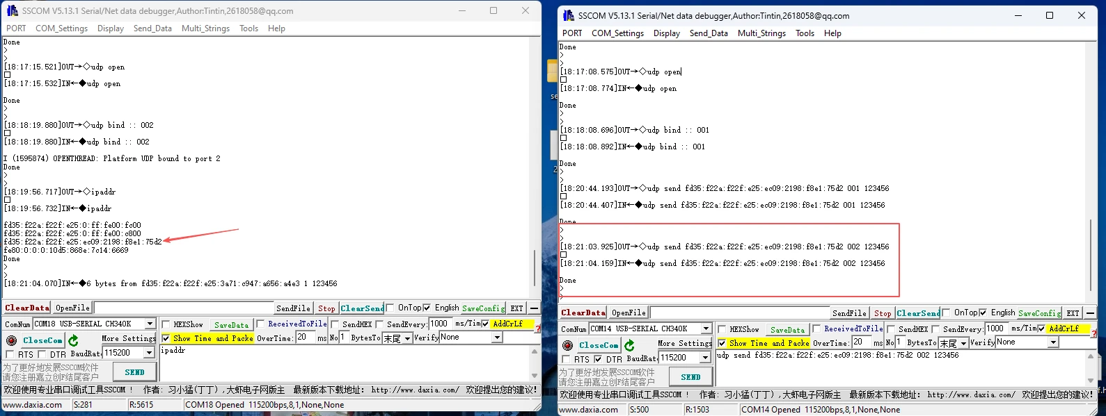
After a successful sending, the Thread device at the corresponding address and the corresponding port number (in this case, the receiving child side) will be able to receive the data.
And on the 7-inch display, one can see the information sent from the 3.5-inch display, as well as the 3.5-inch device\'s own IPv6 address.
Note: It is also possible for the child side or the router to send data, and for the leader side to receive it.