The First Lesson: Installation and Configuration of IDF-IDE and Printing "Hello World" via Serial Port
1. Product Introduction
1.1 product overview
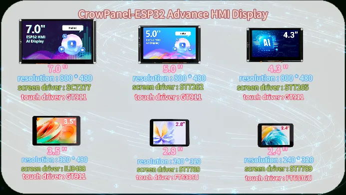
The CrowPanel-ESP32 Advance HMI Display product is divided into 6 sizes, namely 7.0 inches, 5.0 inches, 4.3 inches, 3.5 inches, 2.8 inches, and 2.4 inches.Its main control chip uses ESP32-S3 as the core of the man-machine interface.
The resolution of the 7.0-inch display screen is 800 * 480, the screen driver chip is SC7277, and the touch driver chip is GT911;
5.0-inch display screen resolution of 800 * 480, screen driver chip ST7262, touch driver chip GT911;
4.3-inch display screen resolution of 800 * 480, screen driver chip ST7265, touch driver chip GT911;
3.5-inch display screen resolution of 320 * 480, screen driver chip ILI9488, touch driver chip GT911;
2.8-inch display screen resolution of 240 * 320, screen driver chip ST7789, touch driver chip FT6336U;
2.4-inch display screen with a resolution of 240 * 320, screen driver chip ST7789, and touch driver chip FT6336U.
Which combines powerful processing capabilities, diverse peripheral interfaces, and excellent low-power performance. Its integrated 2.4GHz Wi Fi and Bluetooth 5 (LE), combined with the module's built-in RF antenna, ensure the stability of wireless connection, especially suitable for HMI application scenarios with high requirements for wireless connection.
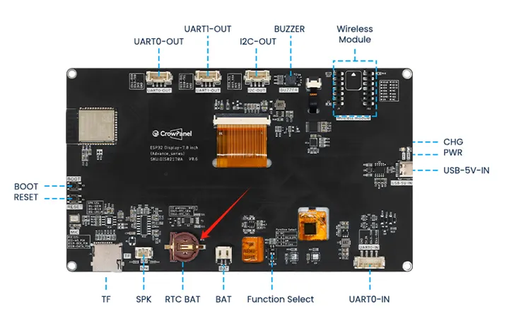
1.2 Hardware feature
After understanding the optimization of the product, let's take a closer look at the hardware changes.
For 4.3-inch, 5.0-inch, and 7.0-inch screens, they only have one USB interface that can be used for code burning, etc.
For 2.4-inch, 2.8-inch, and 3.5-inch, there are two USB ports here. When using the USB port for code burning, you need to first hold down the BOOT button, then press the RESET button, and then release them together to burn the code; The UART0 interface allows for direct code burning without the need to press any buttons.
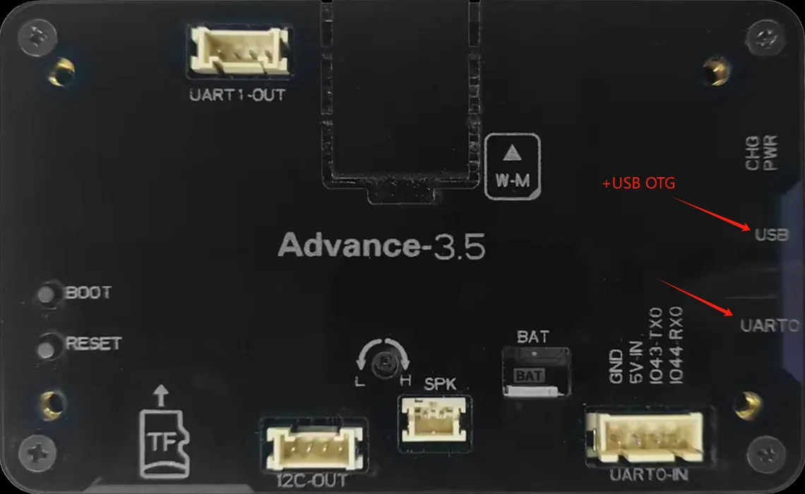
Attention: For the three sizes of 2.4 inches, 2.8 inches, and 3.5 inches, USB OTG function is also available.
The USB OTG function of ESP32-S3 supports switching between host and device roles, allowing for the connection of peripherals such as keyboards, mice, USB drives, or as USB peripherals (such as virtual serial ports, HID devices) to communicate with the host. It is suitable for scenarios such as data transmission, peripheral control, debugging interfaces, custom USB devices, etc. It has high flexibility and simplifies IoT and embedded development.
For 3.5-inch, 4.3-inch, 5.0-inch, and 7.0-inch products, RTC circuits have been added to ensure the continuity and accuracy of system time in the event of a power outage, providing a reliable time reference for data recording and event monitoring.
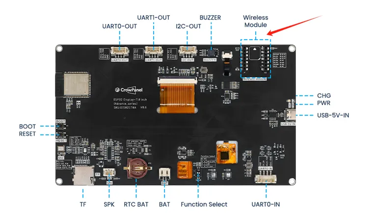
Secondly, this wireless module can be used for communication and data transmission. It supports 802.11 a/b/g/n wireless communication standards, WiFi in the 2.4GHz frequency band, as well as low-power Bluetooth and Bluetooth 5.0, and also supports Zigbee NBIOT、LoRa、UWB、NF2401.
There are also some other interfaces and peripherals available for everyone to use. For example, the I2C interface can be used for sensor devices suitable for using I2C communication; UART0 interface, suitable for sensor devices that use serial communication; SD card slot, capable of meeting local storage requirements; Speaker interface, capable of connecting external speakers for playing songs, etc; Battery interface, which can be used for external battery power supply.
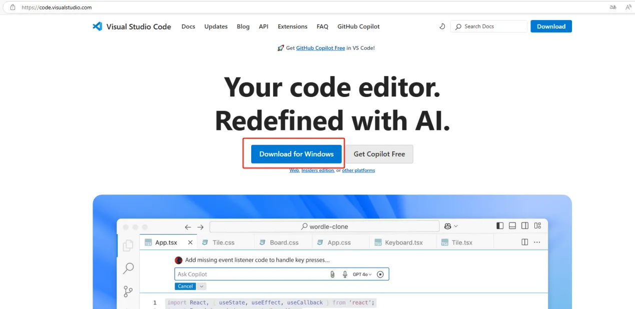
2. Download Visual Studio Code
Open the official website link:
Click to download.
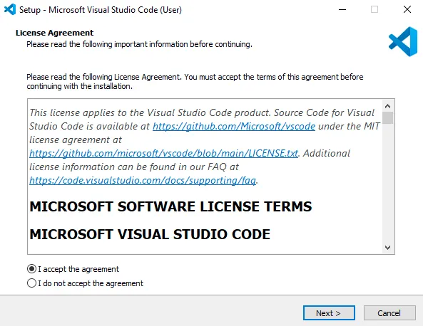
Accept the license agreement and go next.
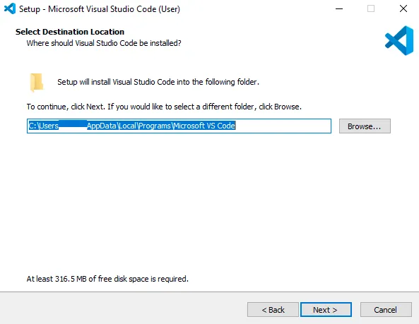
Accept the default location or click 'Browse...' to change the installation location.
Accept the resting default option and click 'Next >'...
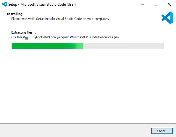
Click install and waiting for the installation ...
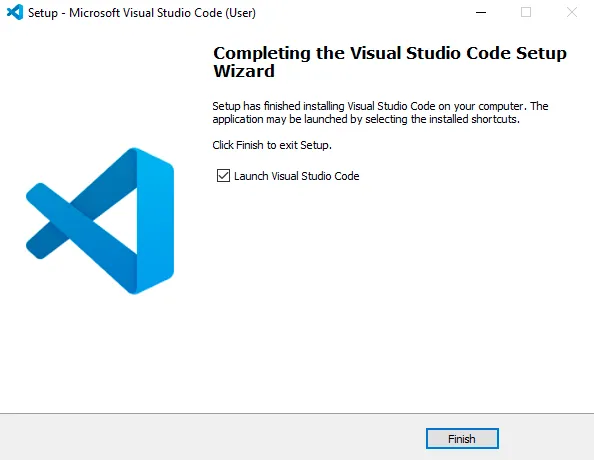
Click 'Finish' to exit the installation and (by default) launch Visual Studio Code
3. Install the extension
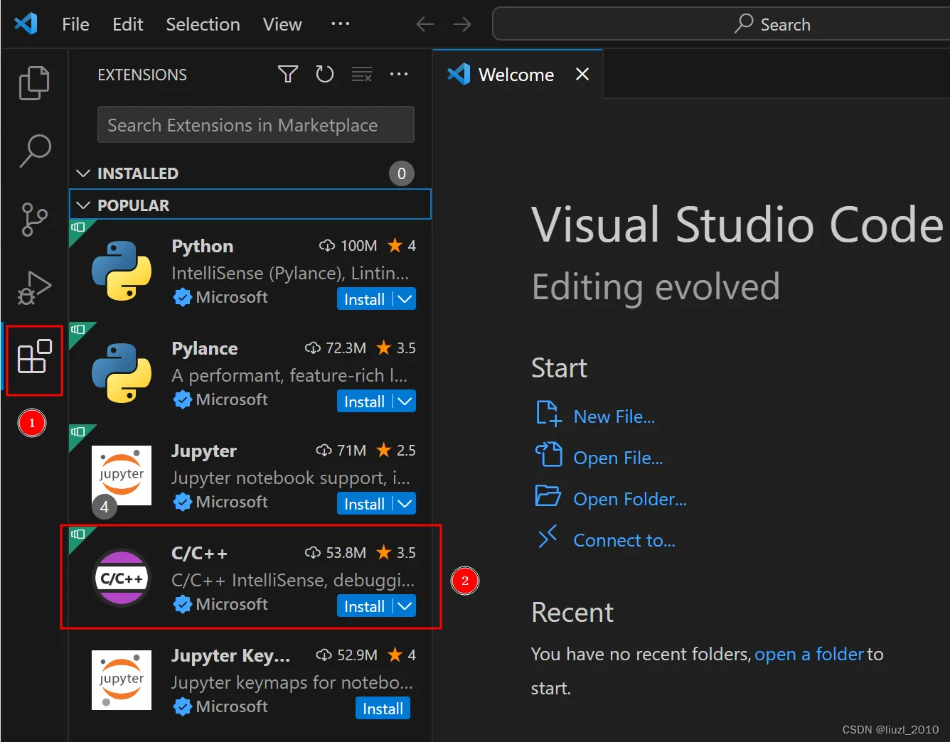
Open Visual Studio Code and open Extension Manager
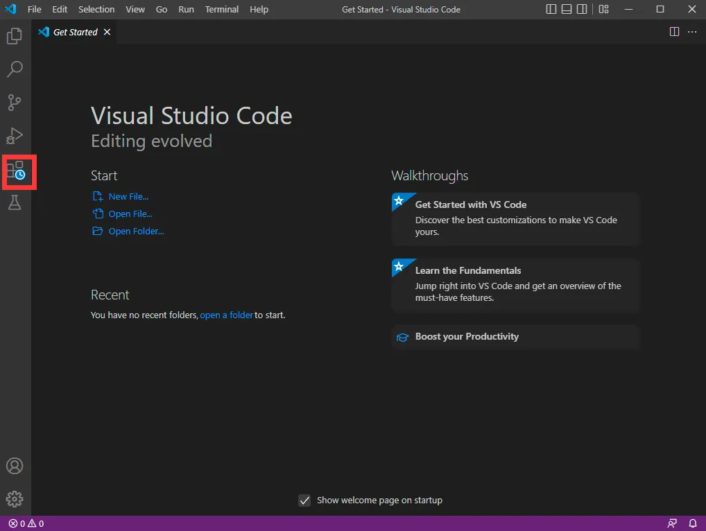
Click on the [Extensions] extension icon.
Select the C/C++ extension plugin and click [Install].
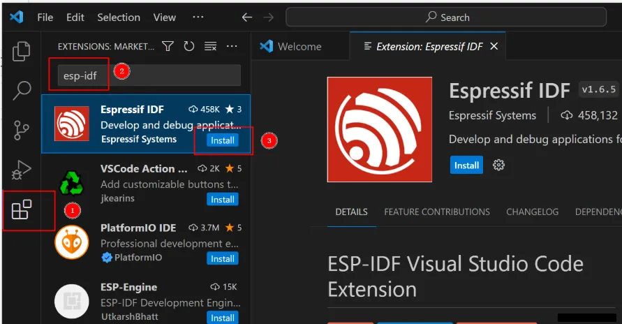
Search for keywords such as espressif, esp-idf, esp32, esp32s2, etc. in the Extensions.
Click [Install] for the esp-idf extension.
Open the command palette.
Click [View].
Select [Command Palette].
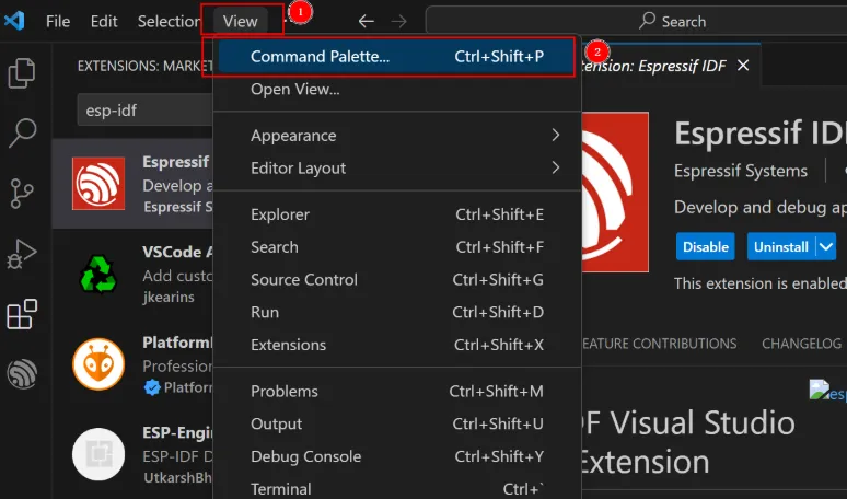
Or press the F1 shortcut key to open the command palette and enter in the command palette: ESP-IDF: Select where to save configuration settings.
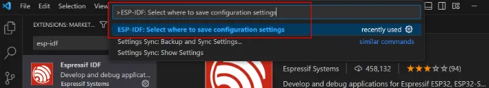
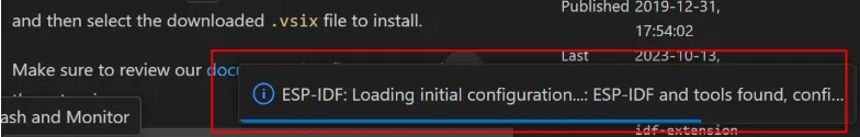
Wait until the following progress bar is completed.
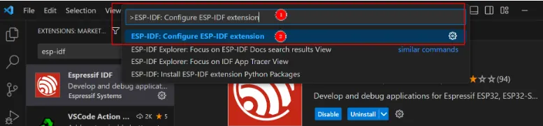
Then enter "ESP-IDF: Configure ESP-IDF extension" in the command palette, and click to select "ESP-IDF: Configure ESP-IDF extension".
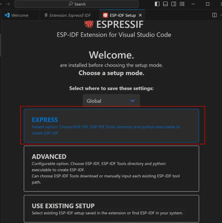
After entering, select [EXPRESS].
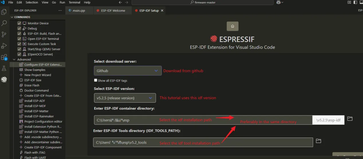
Note: Select version v5.1.1.
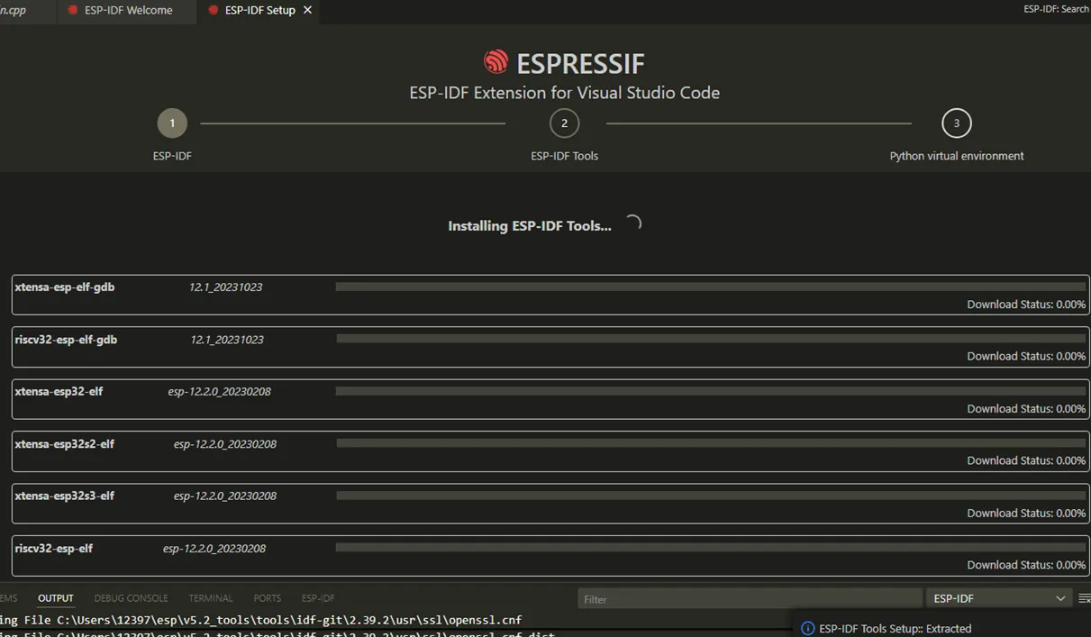
In the following interface,click [Install] to start the installation.
Then, just wait patiently for the installation to be completed.
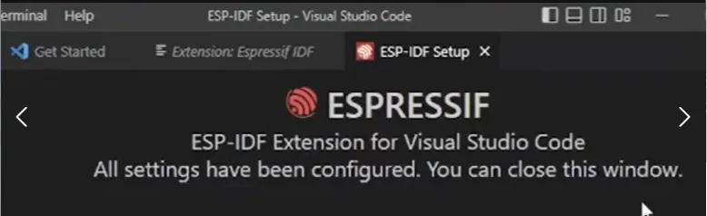
When you see this interface, it means the installation has been completed correctly.
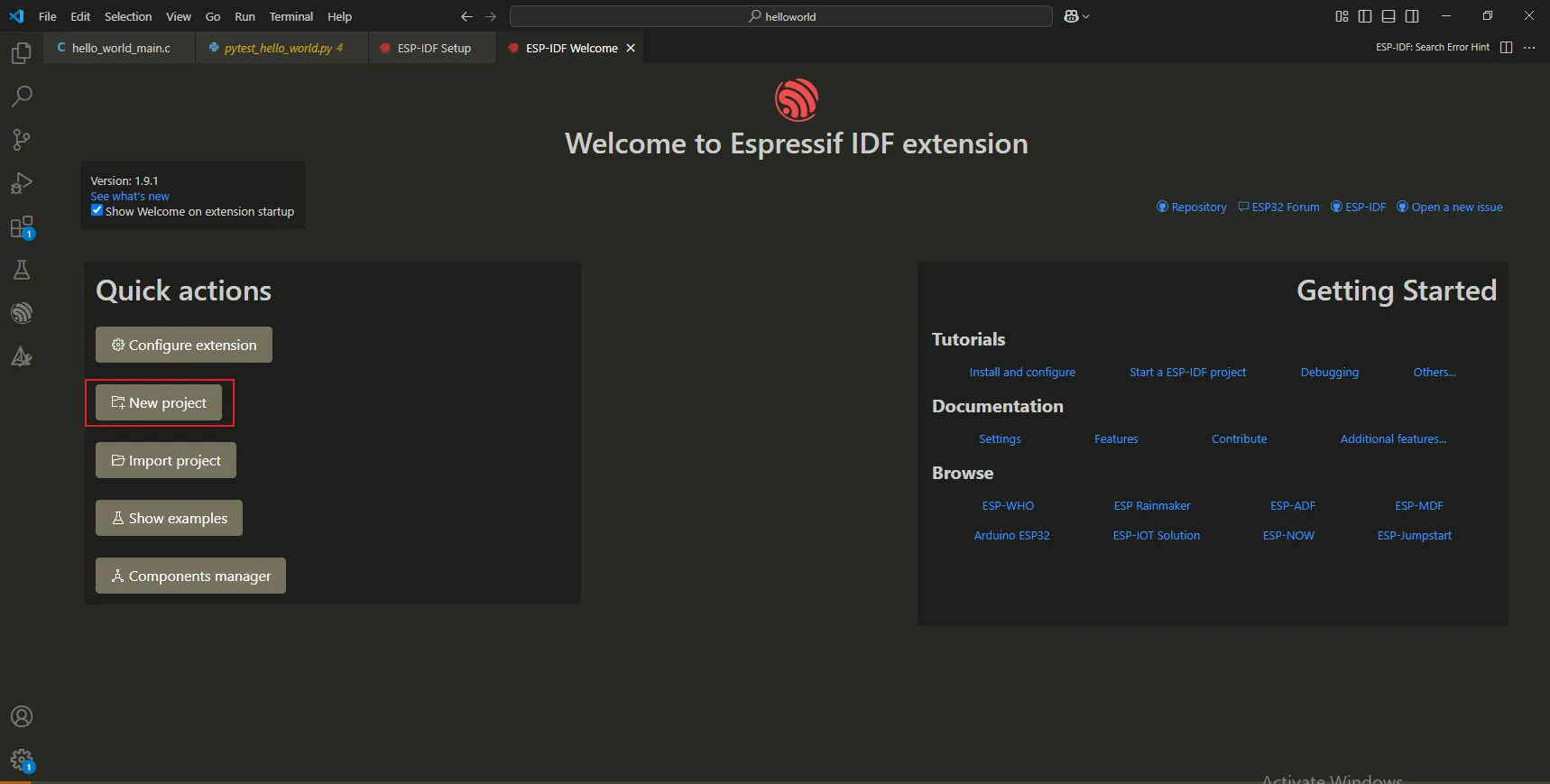
4. Create a new IDF project.
click”New project”.
Fill in the project name, select the save location and the chip model.
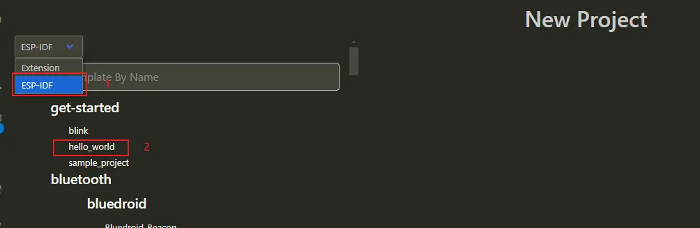
Click "Choose Template".

Select an official Espressif example and choose the “hello_world” template.
Click”Create project using template hello_world”
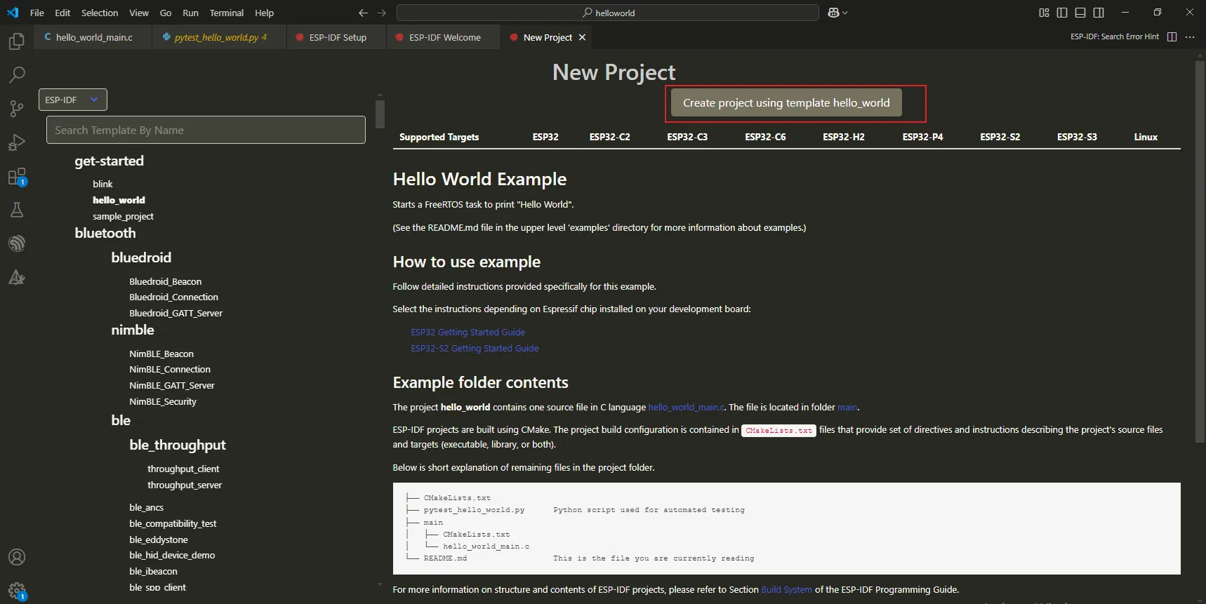
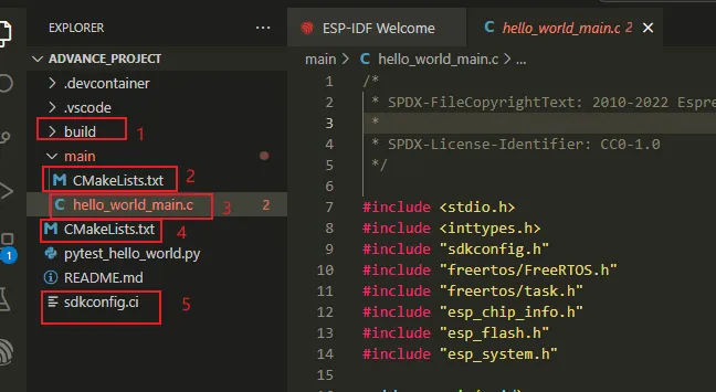
Generate the newly created IDF project.
-
The
buildfolder is the build directory, used to store files generated during the compilation process. -
CMakeLists.txtis the CMake build file for the main application. -
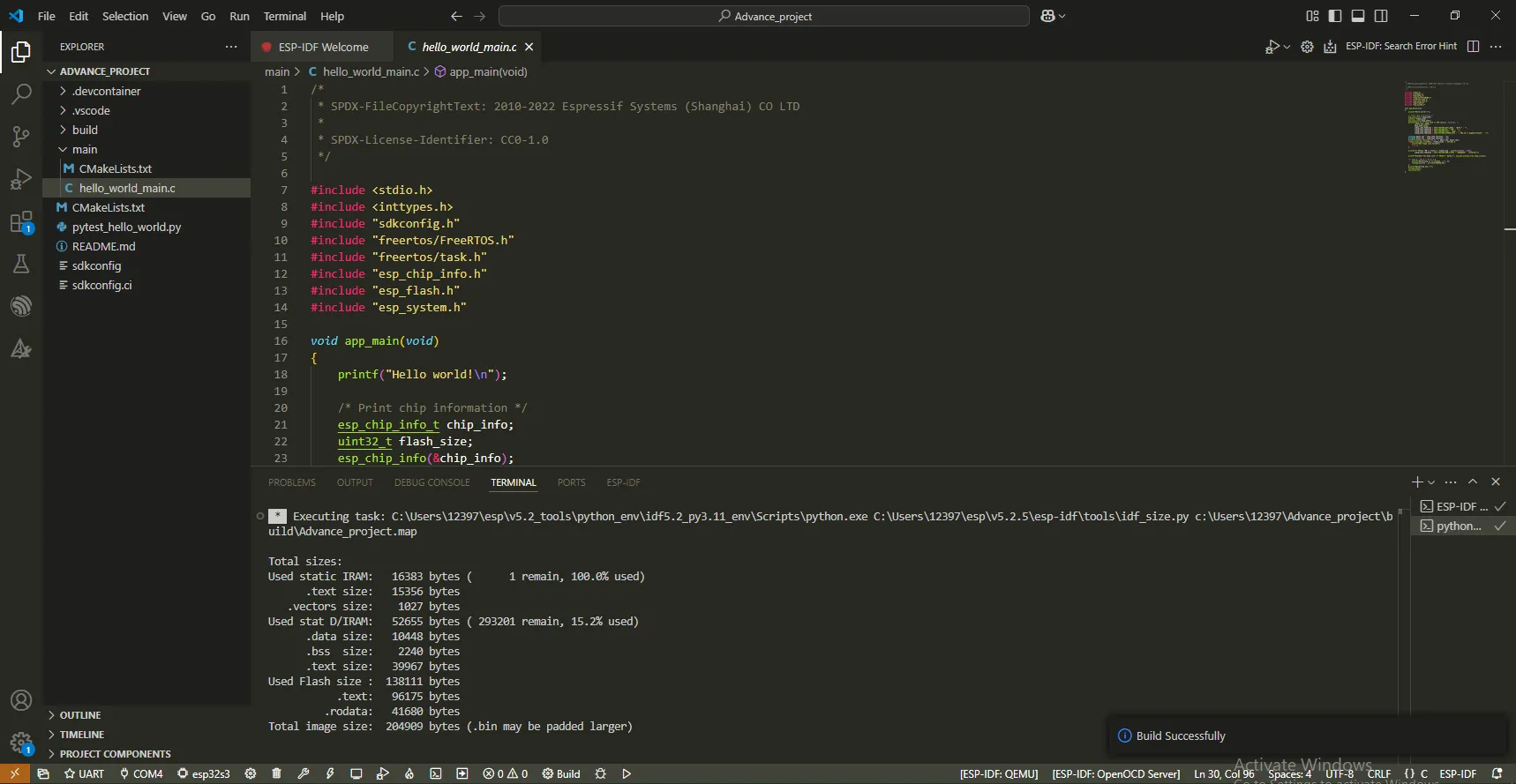
hello_world_main.cis the source file of the main application. -
CMakeLists.txtis the top - level CMake build file, used to configure the entire project. -
sdkconfigis the project configuration file, which saves the configuration ofidf.py menuconfig.
The significance of the header files included in the main program:
-
stdio.h: The function ofstdio.his basically the same as its function in a standard C program. However, there are some specific considerations and extensions, especially in the embedded development environment related to the ESP32 series of chips. -
The function of the
inttypes.hheader file is similar to its function in standard C programming. It is mainly used to provide a series of macros, which can help developers write code that is independent of the size of integer types. -
The
sdkconfig.hfile is a very important configuration header file. It is generated by the project's configuration system, based on the choices made by the user during the project configuration process. -
The
esp_chip_info.hheader file provides some macro definitions and functions, which are used to obtain detailed information about the ESP chip, such as the chip model, functional features, and hardware configuration. -
The
esp_flash.hheader file provides functions and macro definitions related to the flash memory operations on the ESP chip. -
esp_system.his a header file in the ESP-IDF (Espressif IoT Development Framework). It contains functions and macro definitions related to the system-level functions of Espressif chips such as ESP32, ESP32-S, and ESP8266. -
freertos/freertos.his a general header file that includes the core functions of FreeRTOS. -
freertos/task.his a header file specifically used for task management.
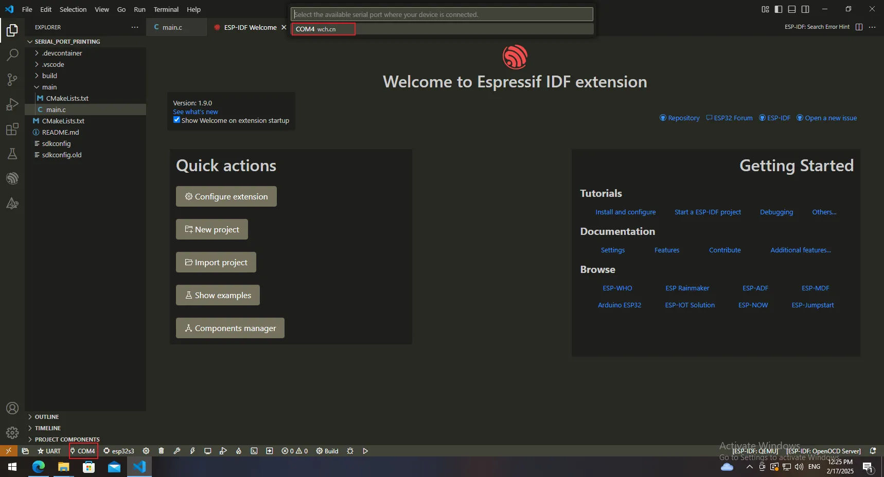
Select the corresponding serial port.
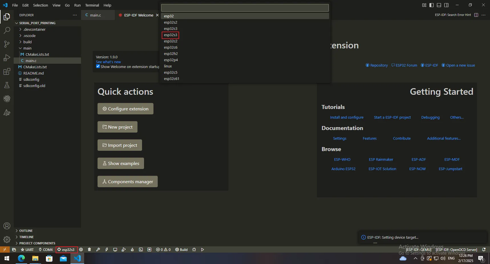
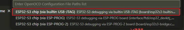
Select the chip type.
Configure the development board options.

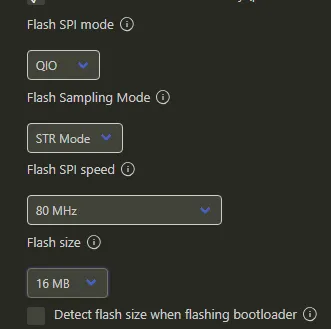
Set the flash parameters.
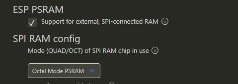
Set the PSRAM parameters.
Click [Save].

Click to compile the project.

Wait for the compilation to complete.
Click "Flash".

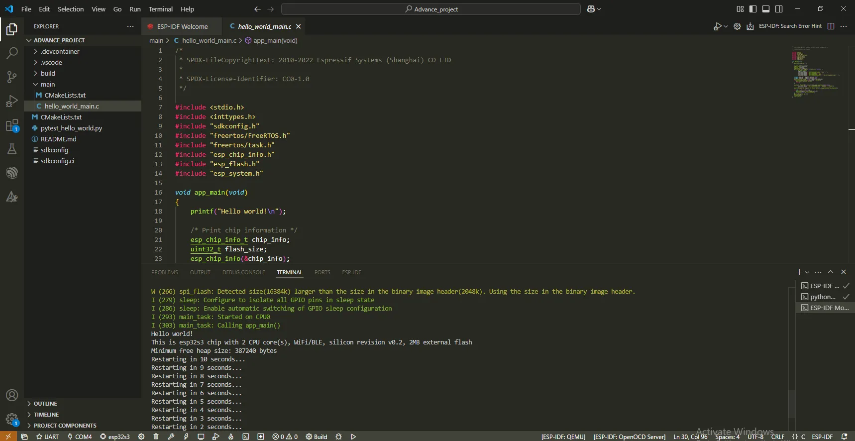
Open the serial port and view the printed information.