Quick Network Configuration of Gateway-ThinkNode Gateway and LR1262 Module
1 Network Configuration of Gateway
Configure the gateway's networking method: Three networking methods are available: Ethernet, Wi-Fi, and 4G cellular (applicable only to the 4G version). Here, the Wi-Fi mode is used.
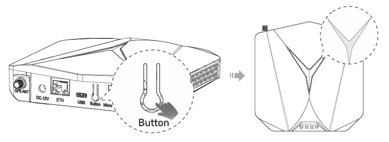
STEP1: Turn on the device's AP hotspot
Press and hold the button for 5 seconds until the top indicator light slowly flashes blue, then it will enter configuration mode.
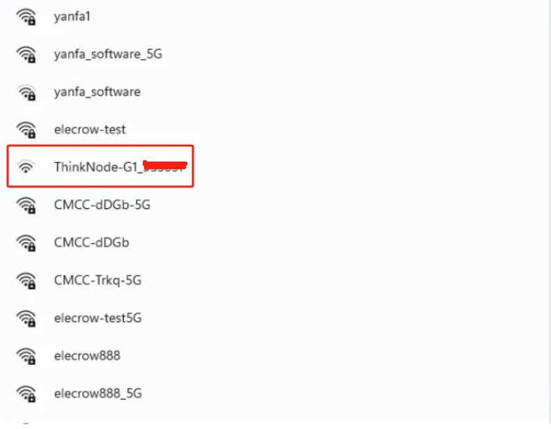
STEP2: Connect to the AP hotspot
The name of the AP hotspot is ThinkNode - G1_XXXXXX (6 - digit MAC address). No password is required, and you can connect directly. Connect your computer or mobile phone to this AP hotspot.
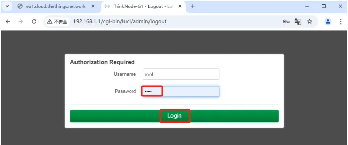
STEP3: Log in to the local console
Enter the IP address (192.168.1.1) in your browser to access the local console. Then log in with the username "root", enter the password "root", and click the "Login" button.
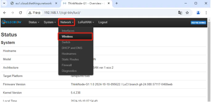
STEP4: Log in to the Luci page, and click Network - Wireless
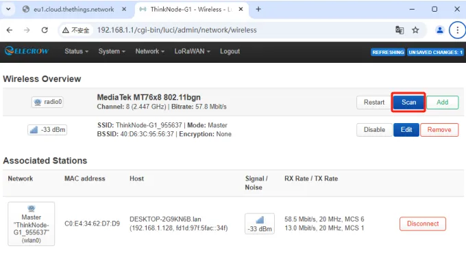
STEP5: Click the "Scan" button to scan for Wi-Fi.
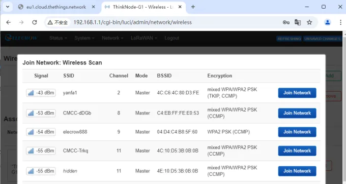
STEP6: Select your Wi-Fi to join the network.
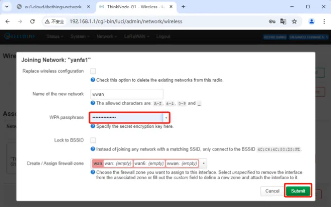
STEP7: Enter the Wi-Fi password, then click "Submit", and save the settings.
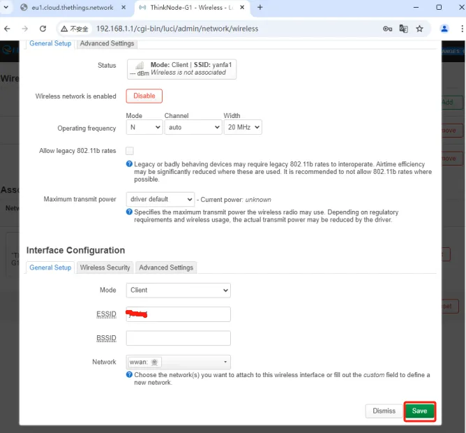
STEP8: Set the gateway's Internet connection method to Wi-Fi.
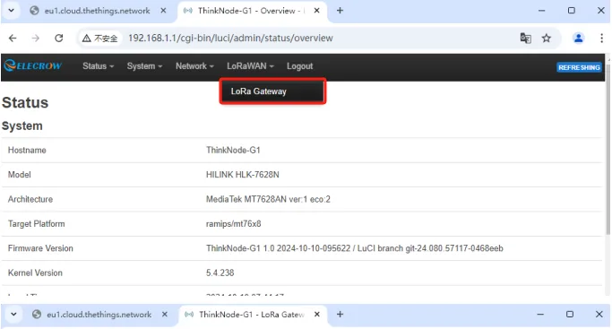
On the Luci interface, click "LoRaWAN" and navigate to the LoRa Gateway interface.
Select the network configuration mode as "WiFi".
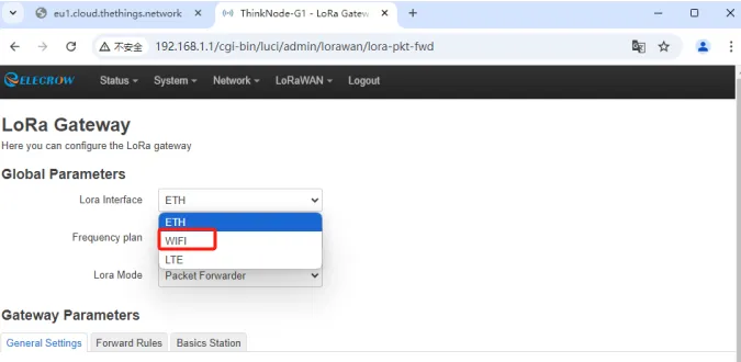
Then click "Save and Apply" to apply your settings.
If the gateway successfully connects to Wi-Fi, the green WLAN indicator will stay on, and the top indicator light will show a steady green light.
2 G1 Gateway Deployment on the TTN Platform
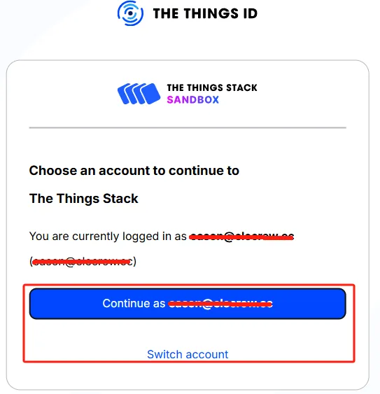
Step 1: Log in to The Things Stack (console.cloud.thethings.network).
If you do not have a TTN account, please register first.
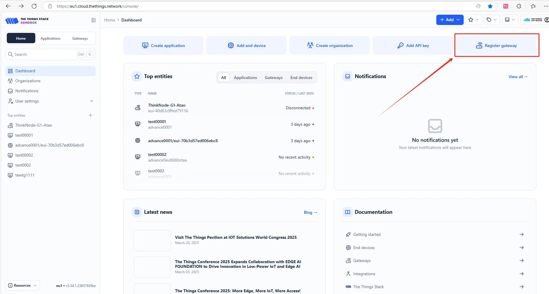
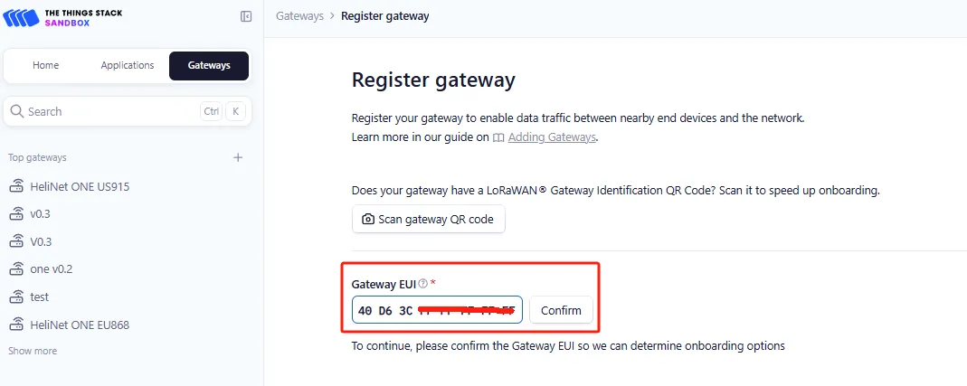
Step 2: Register the gateway, enter the EUI, and click "Confirm".
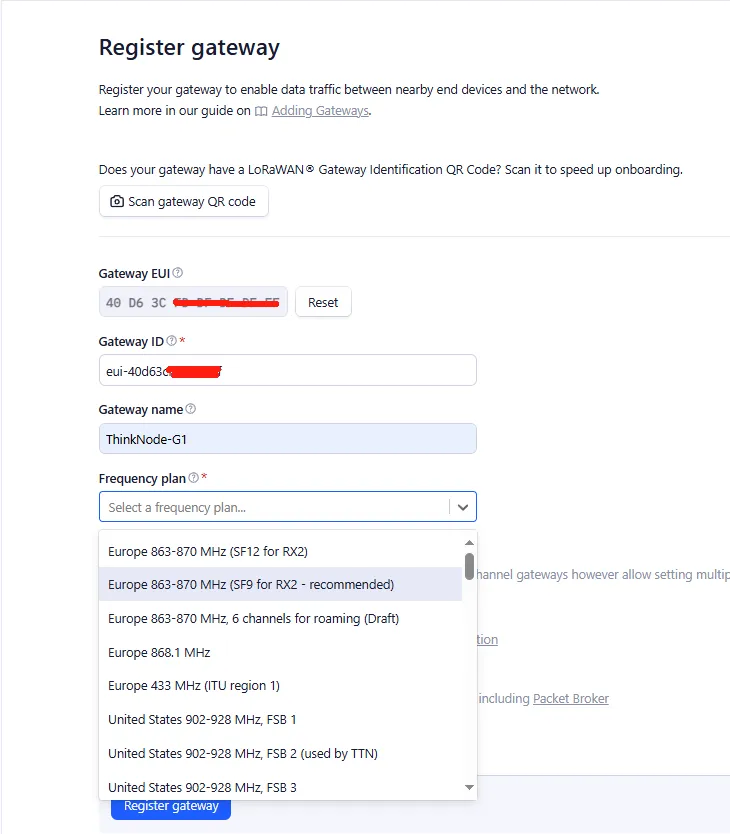
Gateway ID: Usually consists of letters (eui-"Gateway EUI") (the ID must contain only lowercase letters, numbers, and hyphens). Note that letters in the "Gateway EUI" must be converted to lowercase.
Gateway Name: The name of the gateway
Frequency Plan: Select the corresponding frequency according to your gateway version
After successful registration, you can view the gateway in the overview section.
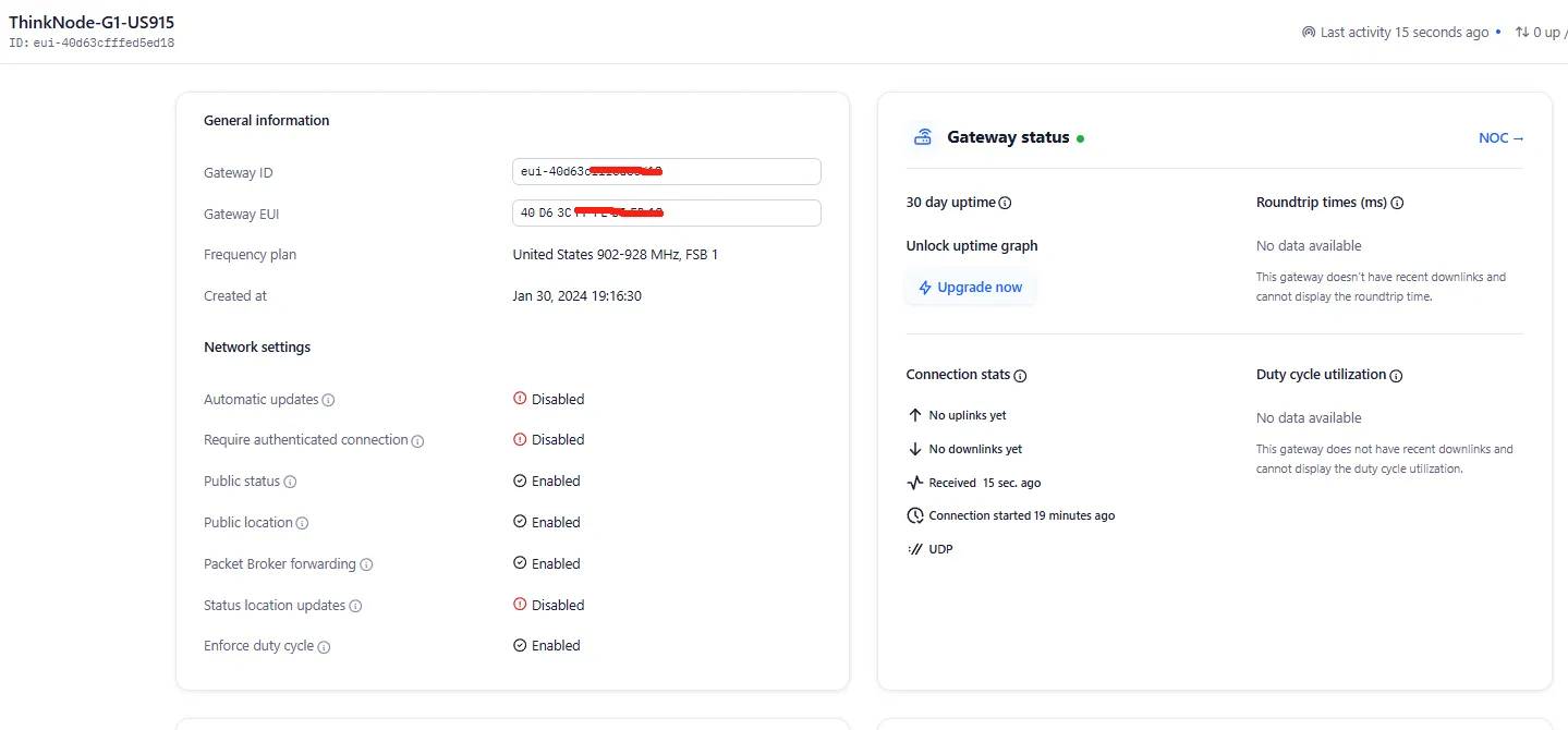
3 Gateway Configuration Corresponding to the TTN Platform
Step 1: LoRa Network Settings
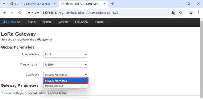
In the Luci interface, click on "LoRaWAN" and navigate to the "LoRa Gateway" page.

Step 2: Set the Mode to Packet Forward
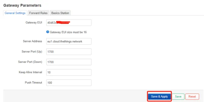
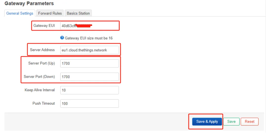
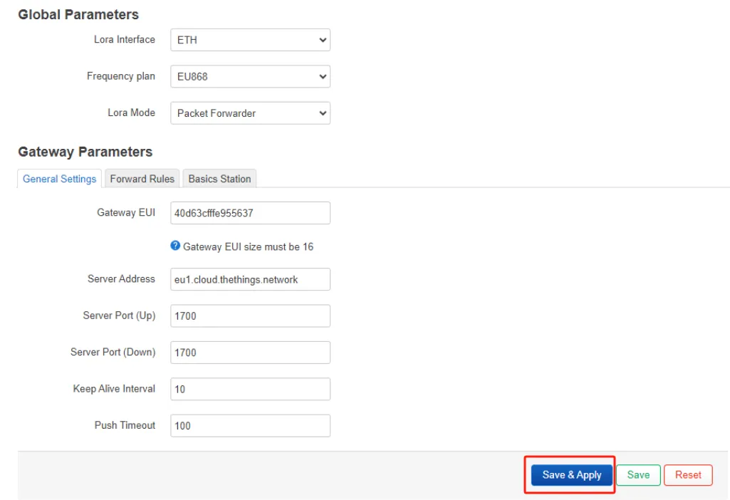
Step 3: Packet Forwarder Settings
① Gateway EUI: It will automatically retrieve the EUI of the connected gateway.
② Server Address: For the Semtech UDP packet forwarder, use "server-address" — this refers to the address where The Things Stack is deployed.
③ Server Port (Up/Down): The uplink and downlink ports are usually set to 1700. Other settings can be left as default or modified according to your requirements.
Step 4: Channel Plan Settings
Select the Region and Frequency plan according to your actual requirements.
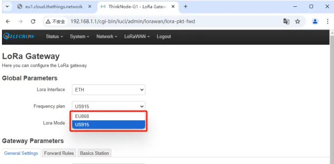
After completing the settings, click "Save & Apply."
Double-click the gateway settings button and wait for the gateway to restart. Now, the gateway is connected to TTN as a Packet Forwarder.
4 Create TTN Node Application
Step 1: Log in to your registered TTN account.
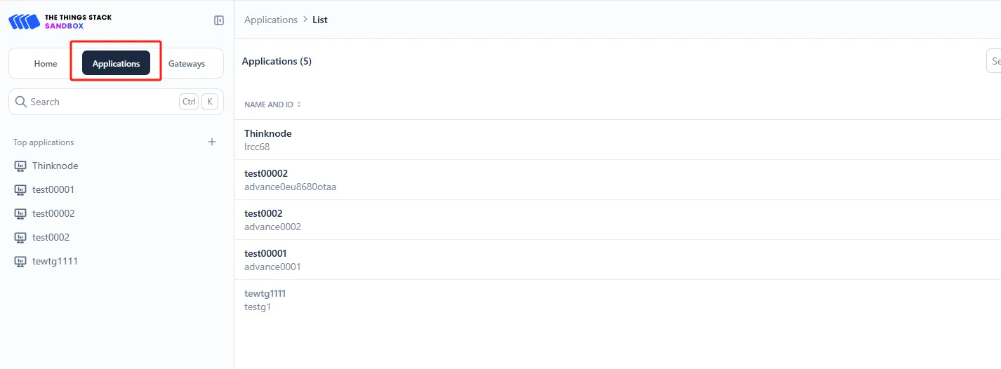
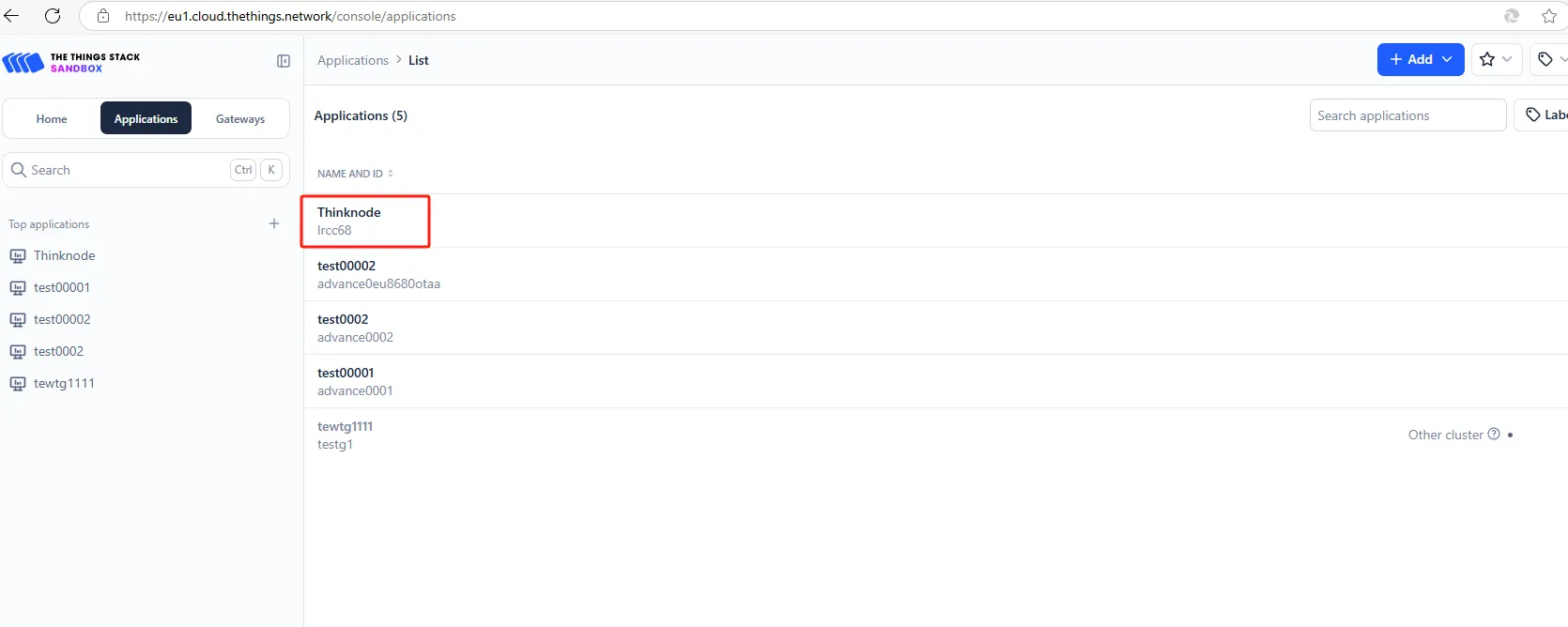
In the TTN server interface, click on "Applications."
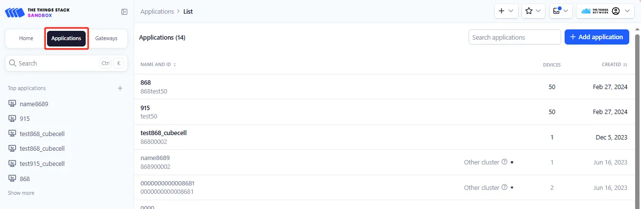
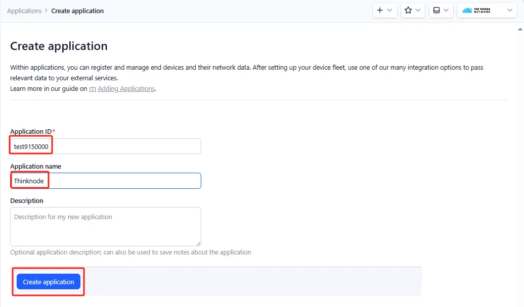
Step 2: Click "Add applications" to start adding a node application.
Enter the Application ID and Application Name, then click "Create application."
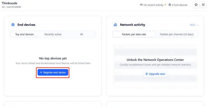
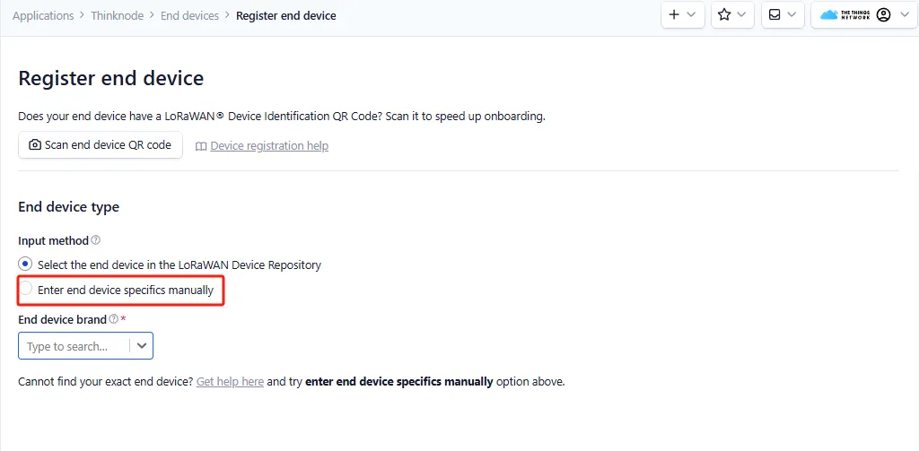
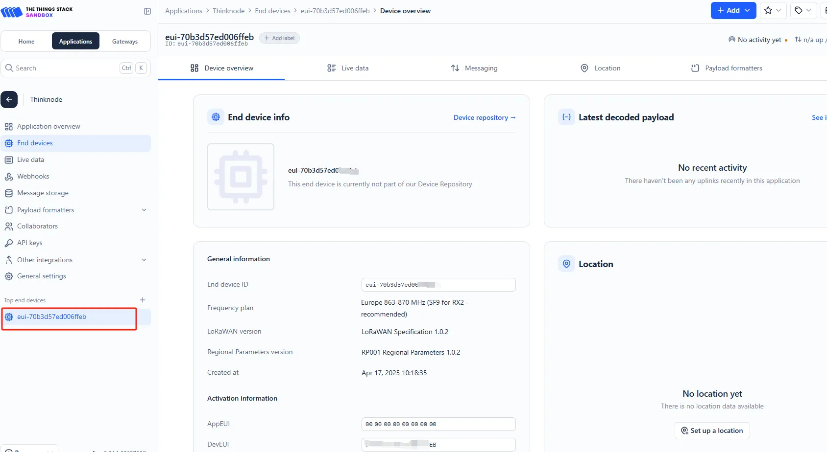
STEP3: Enter the application overview page, click "Register end device" in the lower - left corner to register a new device on the TTN platform.
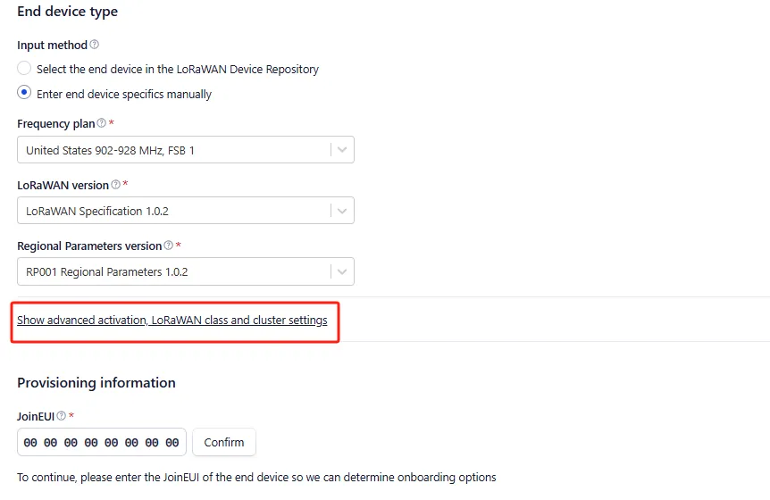
STEP4: In the "Register end device" page, click the "Enter end device specifics manually" option.
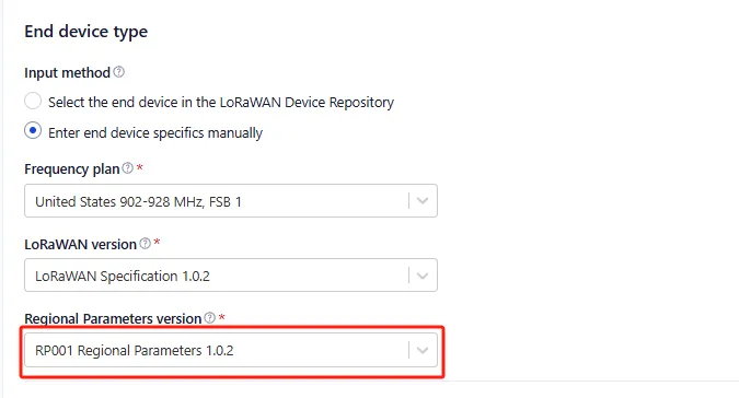
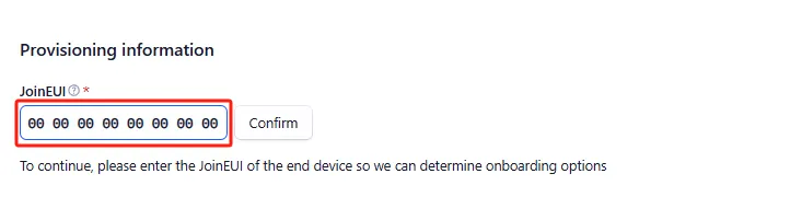
STEP5: Set the Frequency plan, LoRaWAN version, Regional Parameters version, and JoinEUI (APPEUI).
Note: JoinEUI is the same as AppEUI.
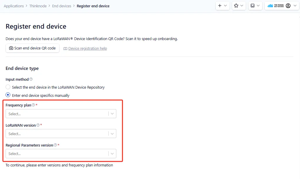
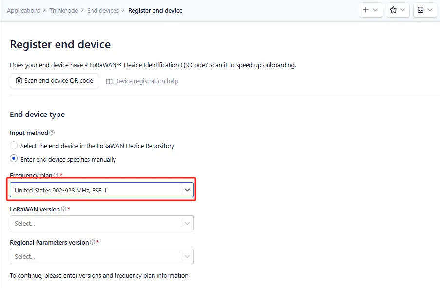
Set the Frequency plan.Note that the frequency band range should be consistent with that of the gateway you are using.
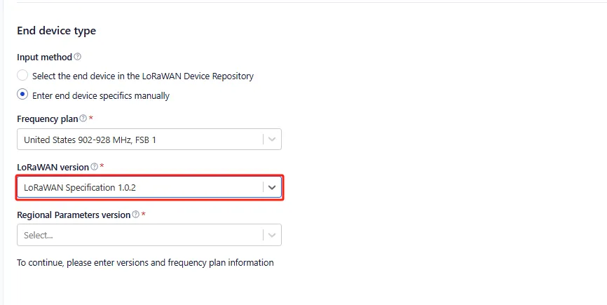
Set the LoRaWAN version.
Set the Regional Parameters version.
Set the JoinEUI (APPEUI).
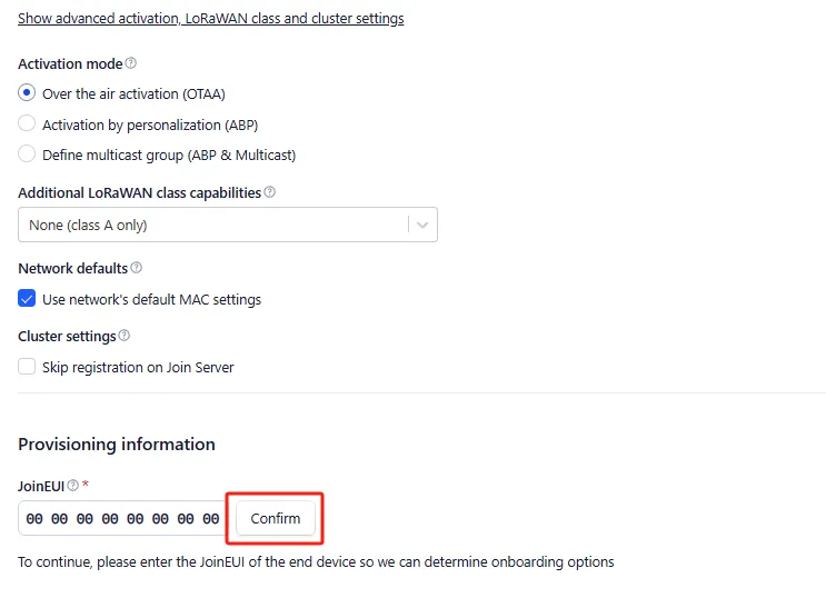
STEP6: Click "Show advanced activation, LoRaWAN class and cluster settings" to configure parameters such as the activation mode and the device operating mode.
When the activation mode is OTAA
Configure it to OTAA mode (i.e., the default mode).
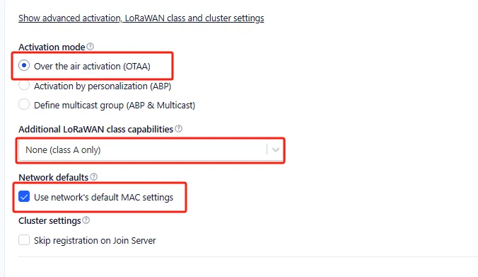
Then click "Confirm".
STEP7:According to the activation mode selected above, configure the corresponding device parameters as shown in the following figure:
Click "Generate" to automatically generate the DevEUI.
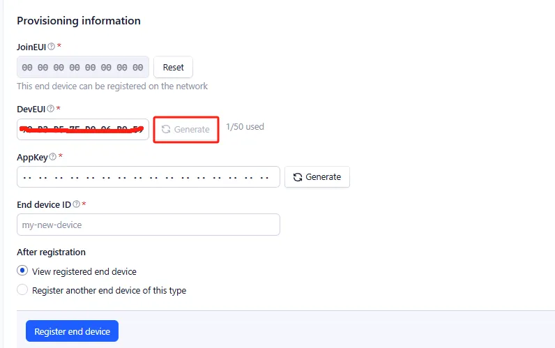
Click "Generate" to automatically generate the AppKey.
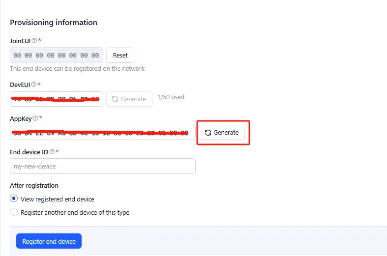
Enter the End device ID.
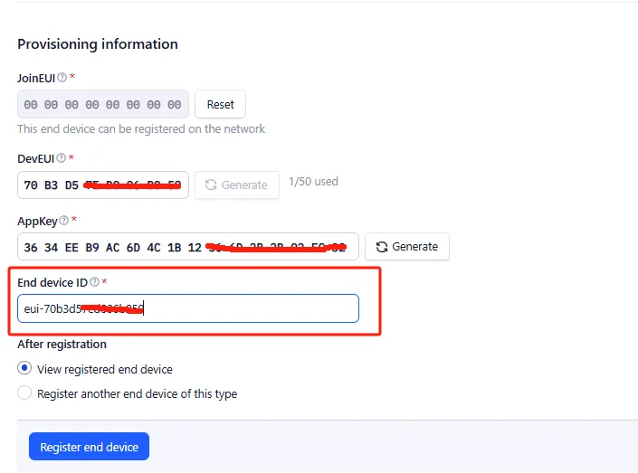
Click "Register end device".
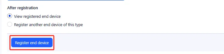
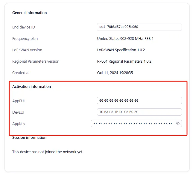
The OTAA device registration was successful.
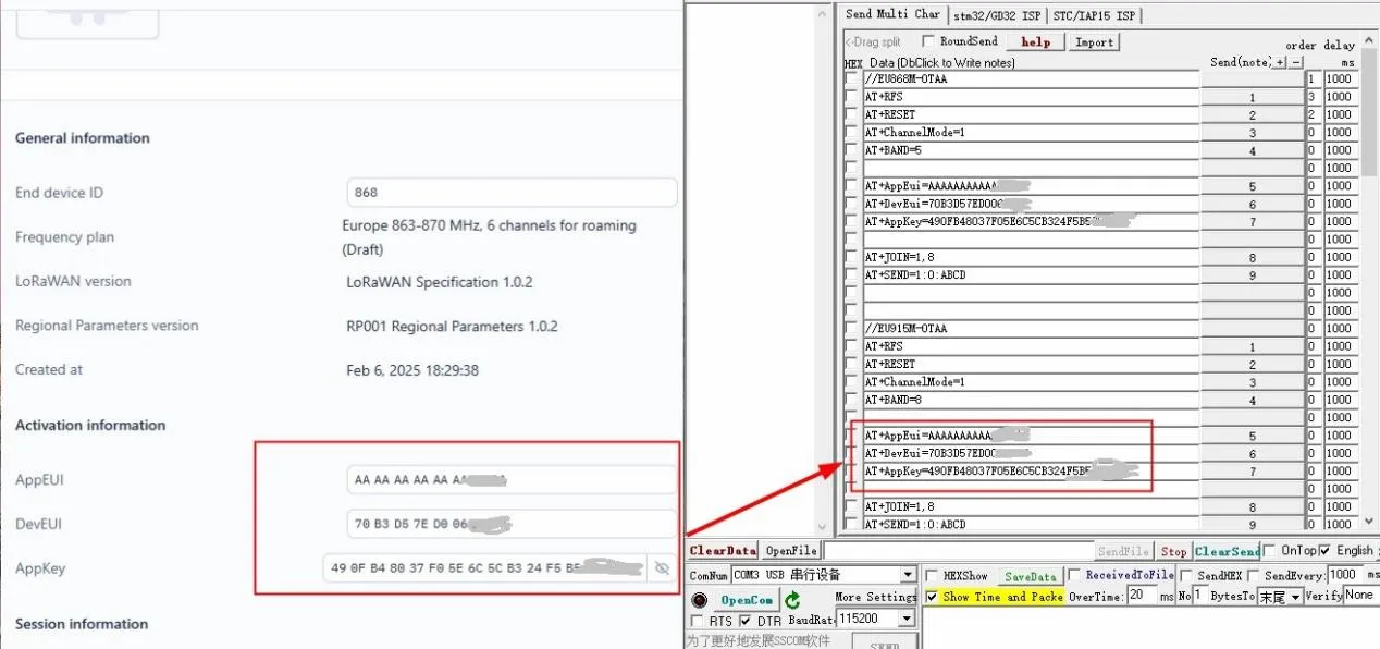
Note: Save the content in the Activation information, which will be used when sending AT commands later.
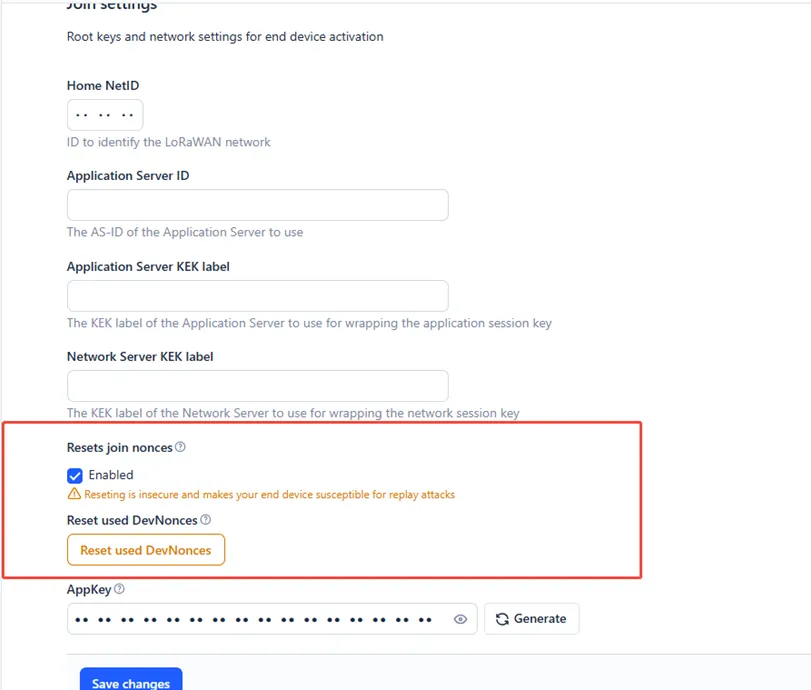
Note: Since LoRaWAN does not allow reusing network join, when ignoring the already used devNonce, the node can test network join indefinitely.
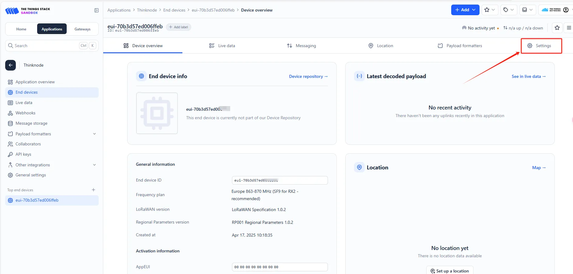
Click on "Applications" -> Application Name -> "End Devices" -> Node Name -> "Settings".
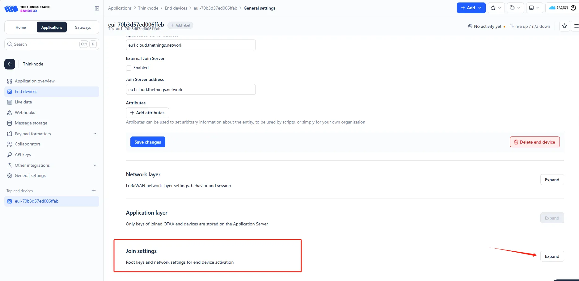
Select "Join Setting".
Enable "Reset join nonces".
By creating a TTN application node, communicate with the gateway to upload node and gateway communication data to the TTN server.
Prerequisites:
①A gateway has been created on TTN, and the gateway is connected and running normally.
②A node application corresponding to the gateway's frequency range (OTAA/ABP) has been created on TTN.
Hardware Preparation:
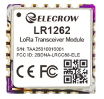
①LR1262 Long-Range LoRa Wireless Transceiver Module
②PC
③TYPE-C data cable
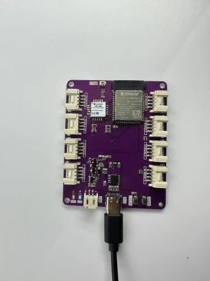
Plug the LR1262 mainboard into the TYPE-C data cable.
Software Preparation:
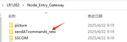
Open the LR1262 node gateway join code provided by us.
Code link:
https://github.com/Elecrow-RD/LR1262-Long-Range-LoRa-Wireless-Transceiver-Module
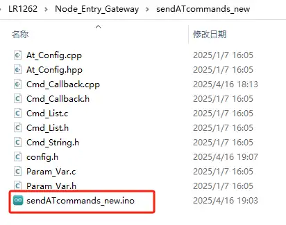
Open the code using Arduino IDE.
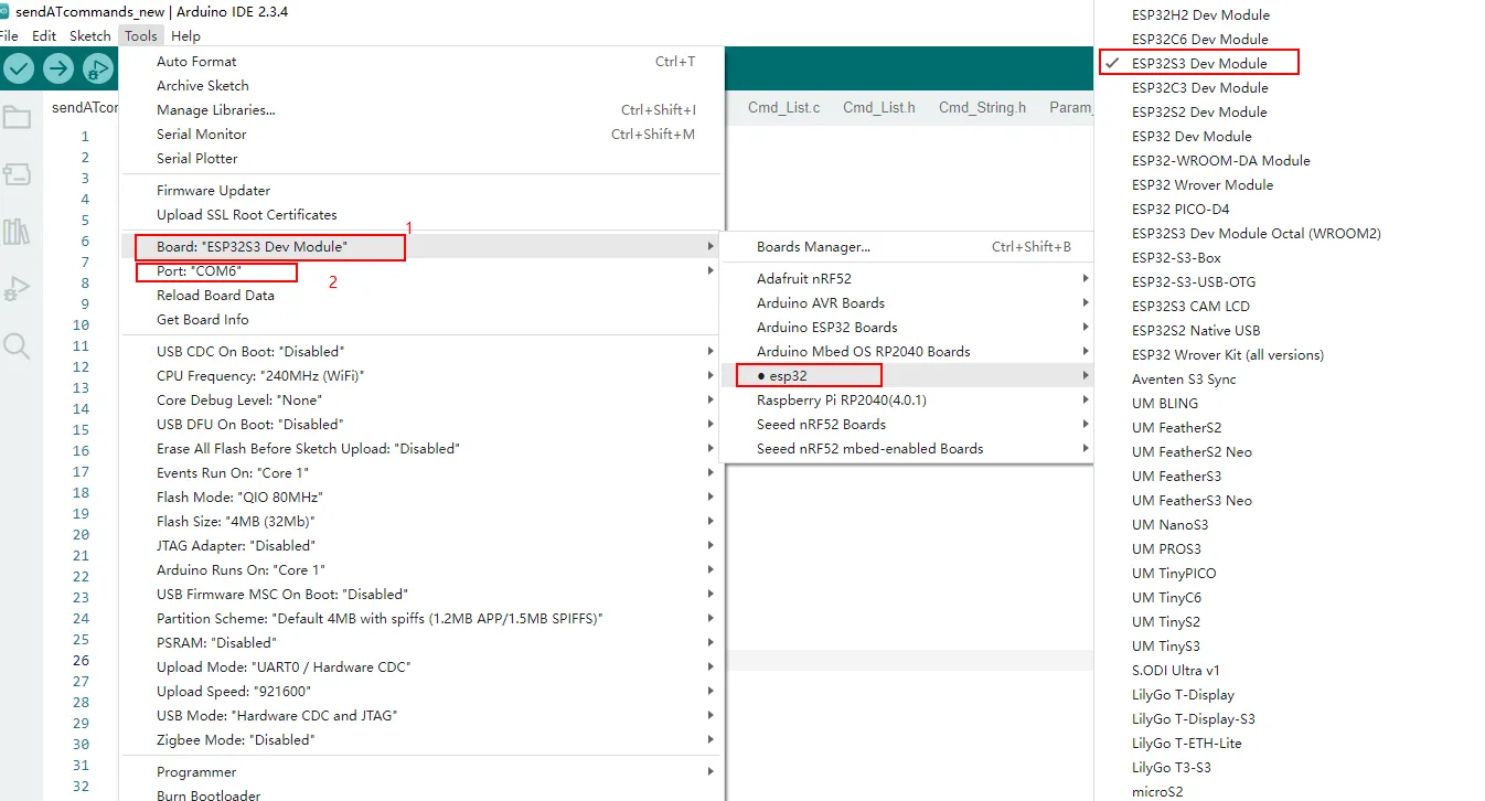
Since the LR1262 uses the ESP32-S3 as the main control chip, you need to install the ESP32 development board.
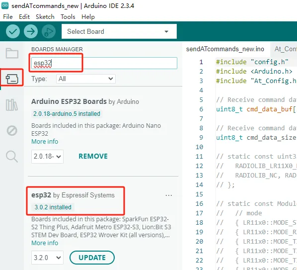
After downloading, make sure to pay attention to the configuration during the flashing process.
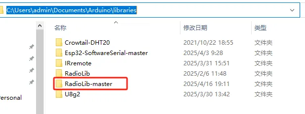
Remember to replace with the library files we provided (refer to the path). (This code only requires the installation of the RadioLib-master library.)
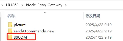
2 SSCOM Serial Port Tool After successfully flashing the above code, open the serial port tool.
Through the SSCOM serial port tool, send AT commands to configure the LR1262 Node Board as an OTAA/ABP node application in TTN, and by sending AT commands, add the LR1262 Node Board to the LoRaWAN network. The node will then communicate with the gateway and upload real-time communication data to the TTN server. Use the OTAA mode to join the LoRaWAN network (the LR1262 Node Board uses this network join method by default).
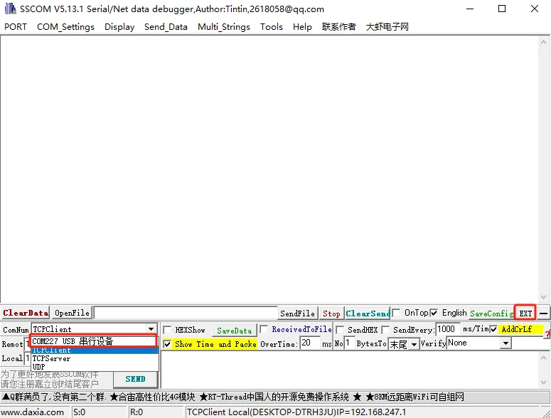
Step 1: Open the SSCOM serial tool in the serial port assistant, select the USB COM port recognized by the computer, and click "EXT," as shown in the image below:
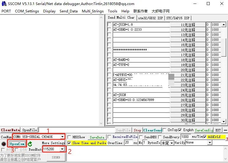
Step 2: In the expansion interface of the serial port assistant, make the following selections and input the AT command information:
(1) Serial Port Settings
Baud Rate: 115200
Check the option for "Carriage Return and Line Feed"
Open the serial port and select "Data Terminal Ready," then click "opencom."
(2) Node Gateway Configuration Steps (Send AT Commands)
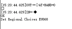
① AT+BAND=0: Set the LoRaWAN frequency band to EU868 (Europe 868MHz).
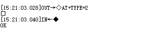
② AT+TYPE=2: Configure the device to use the OTAA (Over-the-Air Activation) network join mode.
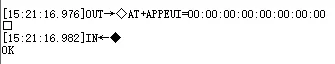
③ AT+APPEUI=00:00:00:00:00:00:00:00: Set the Application Identifier (AppEUI) (Replace with the actual value).
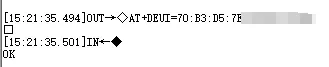
④ AT+DEUI=70:B3:D5:7E:xx:xx:xx:xx: Set the Device Unique Identifier (DevEUI) (Replace with the actual value).
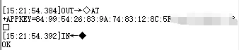
⑤ AT+APPKEY=84:99:54:26:83:9A:xx:xx:xx:xx:xx:xx: Set the OTAA network key (AppKey) (Replace with the actual value).
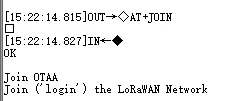
⑥ AT+JOIN: Initiate the OTAA network join request to connect to the LoRaWAN network.
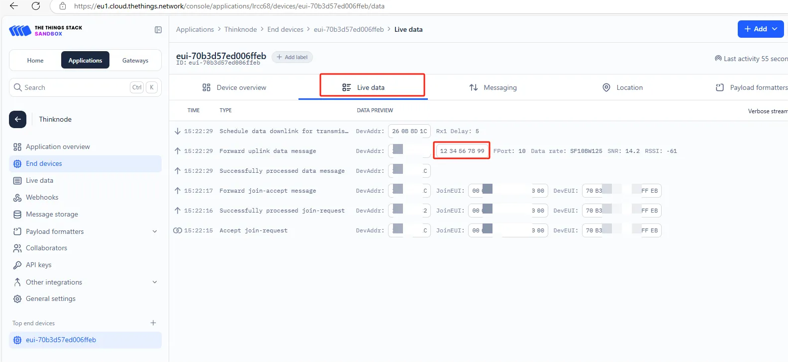
⑦ AT+SEND=10:0:1234567899: Send data "1234567899" through FPort 10.
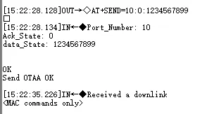
You should be able to see the data received on the gateway side.
Note that you need to replace the DevEui, AppEui, and AppKey with the DevEui, AppEui, and AppKey from the OTAA node application you have created.