Pico HMI 2.8-inch Arduino Tutorial
Overview
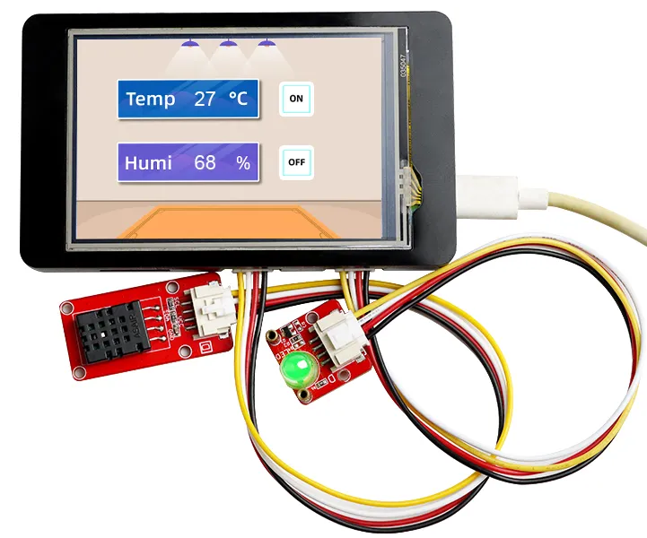
The example tutorial is an environmental monitoring project, demonstrate how to create a UI and use a DHT20 sensor to obtain the ambient temperature and humidity and display it on the screen; and how to control the LED on and off by the buttons on the screen.
In this tutorial, we will show you how to design the UI with SquareLine Studio, and show you how to upload the code with Arduino IDE.
Hardware Preparation
| CrowPanel PICO 2.8'' HMI | Crowtail-DHT20 | Crowtail-LED | USB-C Cable |
|---|---|---|---|
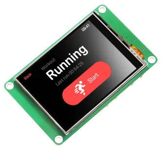 | 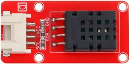 | 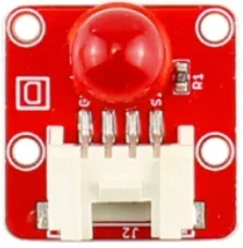 |  |
 | | | |
Design UI file with SquareLine Studio
Get Started with SquareLine Studio
Please click the card below to learn how to download the SquareLine Studio, and how to export the demo UI file.

Design UI file with SquareLine Studio
Let's start learning how to create our own UI after getting an initial understanding of SquareLine Studio.
-
Open the SquareLine Studio and create a project. Select "Arduino"->"Arduino with TFT_eSPI".
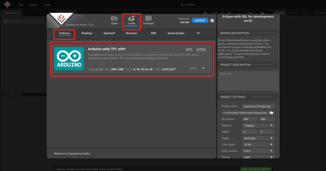
Note:
When select the Arduino framwork, there's only one option "Arduino with TFT_eSPI". By choosing this, the squareline studio will generate a template code suitable for the TFT_eSPI library. However, squareline studio not only supports the TFT_eSPI library, it supports a variety of libraries to suit different hardware and application needs. For example, Adafruit_GFX library, LovyanGFX etc.
After using SLS to generate UI code, we then use different graphics libraries according to different hardware and modify the corresponding code to display the content you design.
-
Set the name of the project, set the screen resolution to 320*240, set the color depth to 16bit, and keep other default settings. After setting, click CREATE to create the project.
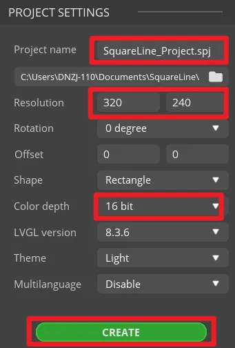
- 16-bit color depth: can represent 65,536 colors through RGB 5:6:5 sub-pixel representation, that is, each RGB channel occupies 5 bits and 1 bit (a total of 16 bits) to represent colors.
-
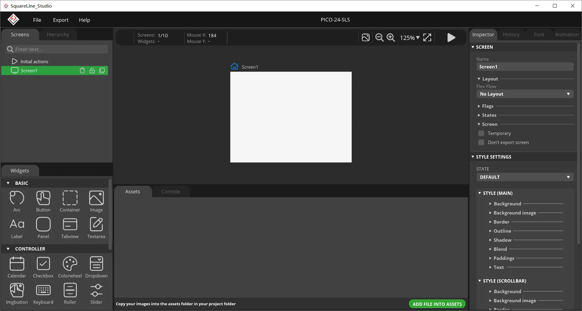
After creation, enter the following interface with a blank background.
-
In the "Assets" area, click "ADD FILE TO ASSETS" to add custom images or icons.
Please click
 to download the custom images used in this tutorial.
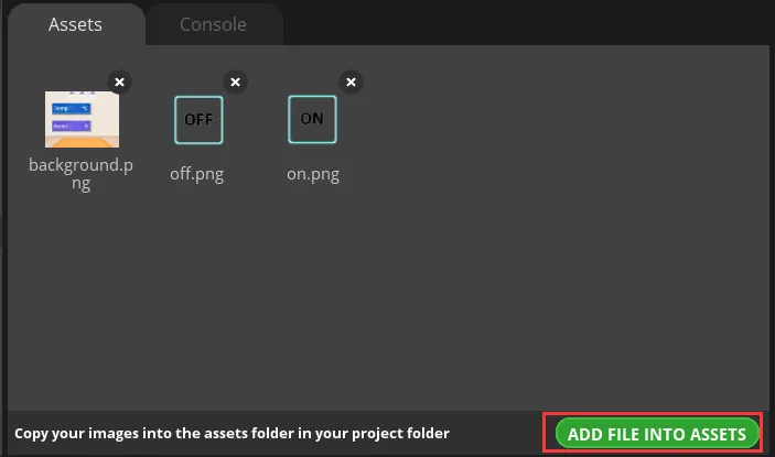
Note:
Images only support webp format. The pixels of the image need to be smaller than the pixel size of the screen used in your project. The size of each image should not exceed 100k, preferably within 30k, to provide a smooth display effect.
-
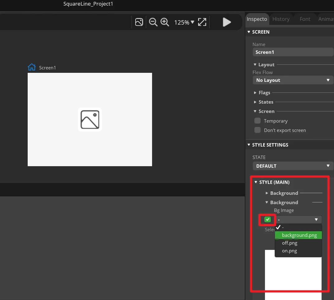
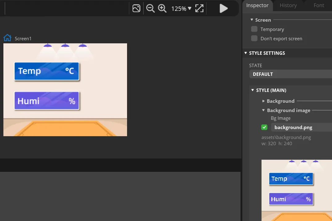
Add background.
Find "Inspector"->"STYLE SETTING", click to expand "STYLE(MAIN)", then click the 2nd "Background"(in v1.3.4 is "Background image"). Check the "Bg Image" and select the background image.
-
Add Label widget to display temperature and humidity.
Click "Label" in the "Widgets" area, and "Label1" will be added to the current Screen.
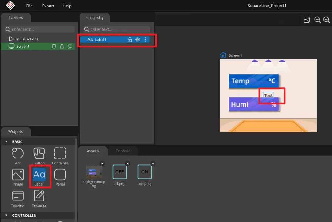
The position and size of the label can be adjusted by dragging the mouse. You can also directly enter numbers in the Inspector→LABEL→Transform to adjust.
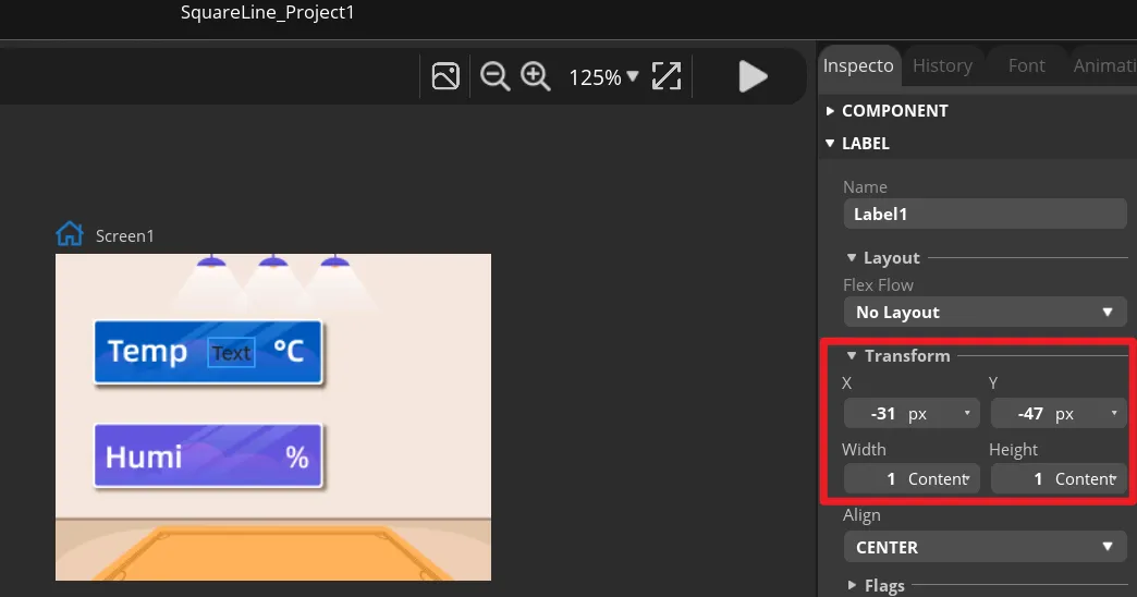
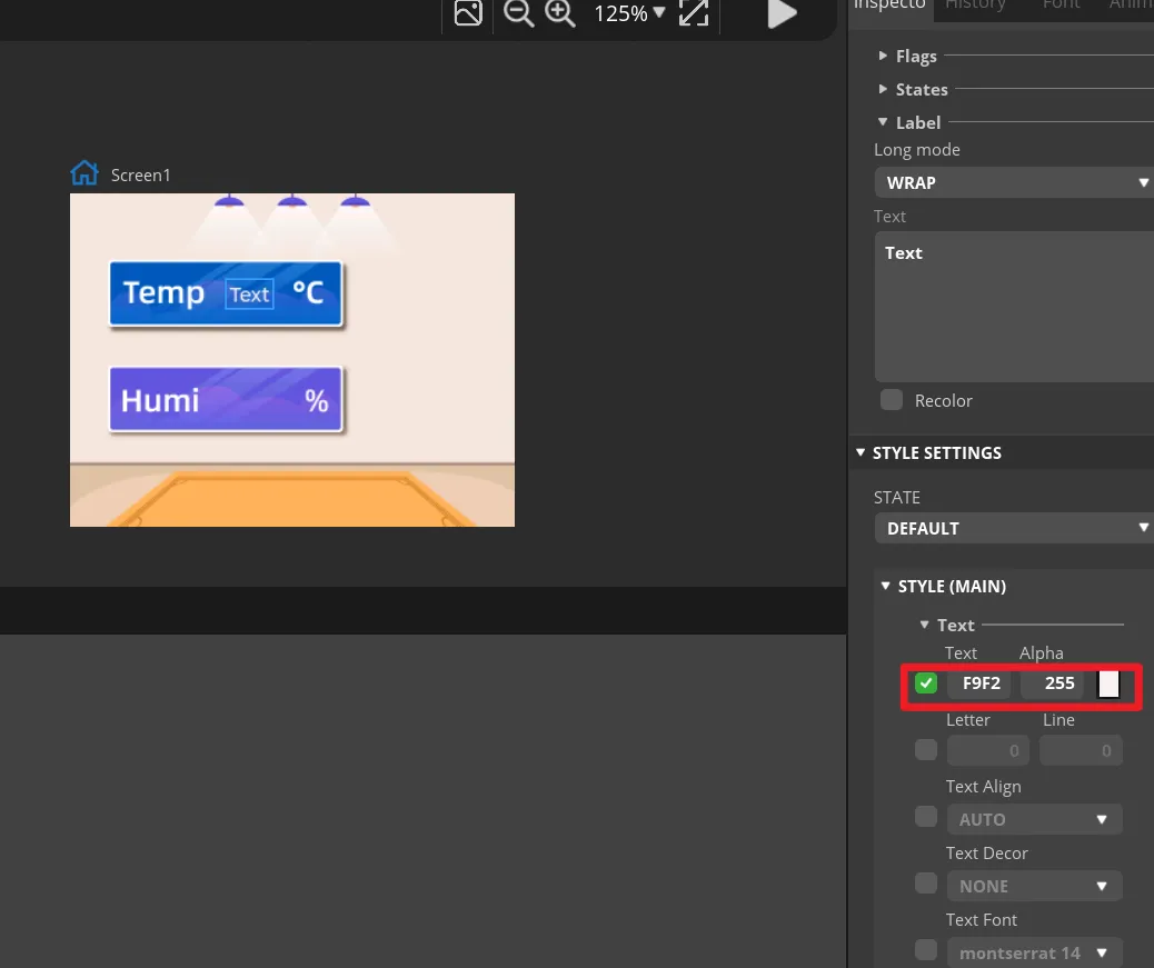
You can set the font color and other attributes in STYLE SETTING→STYLE(MAIN).
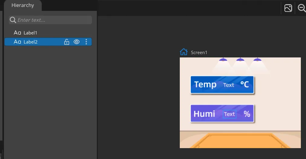
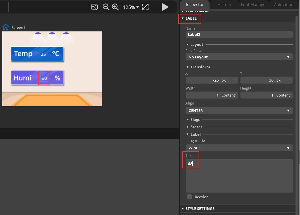
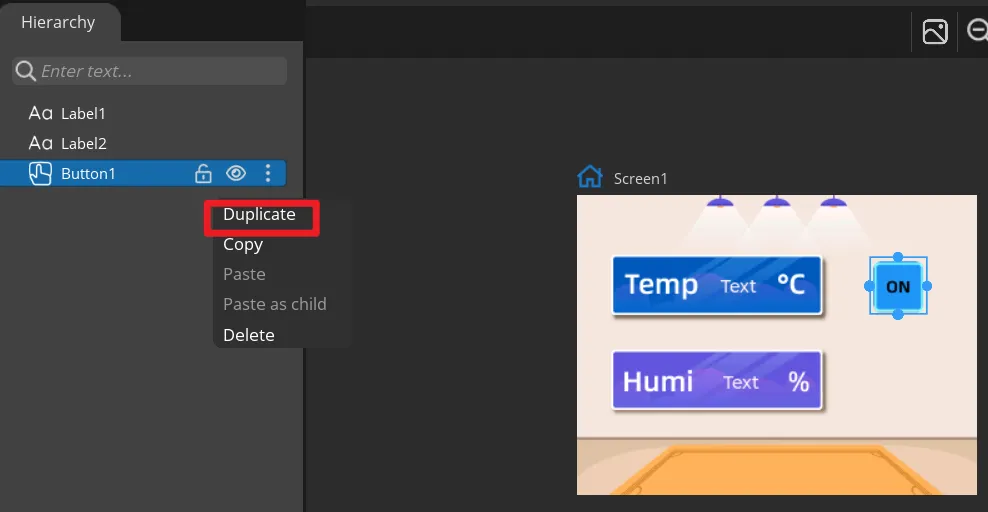
Add a Label2 to display the humidity value in the same way. You can also directly right-click the Label1 to duplicate it.
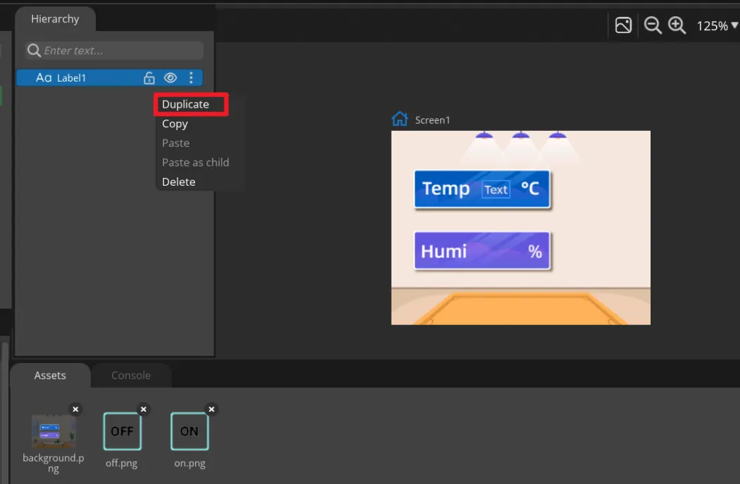
Then set different positions for the Label2.
Modify the text content to display a default value.
-
Add Button widget to control the LED.
Click "Button" in the "Widgets" area, and "Button1" will be added to the current Screen.
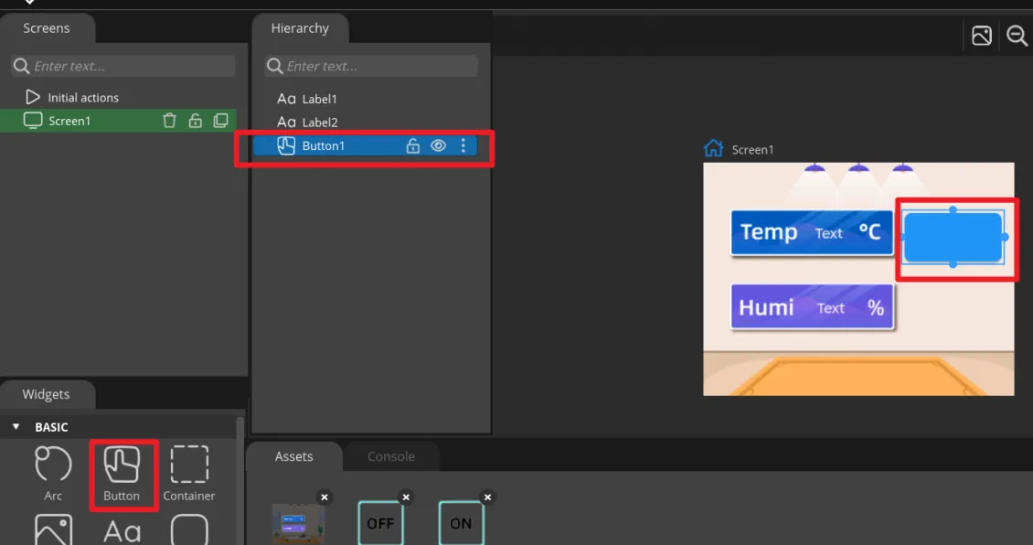
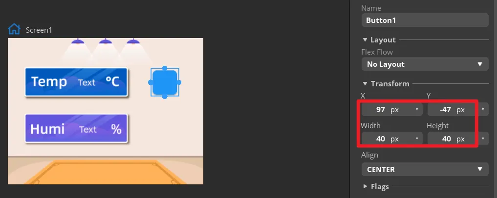
The position and size of the label can be adjusted by dragging the mouse. You can also directly enter numbers in the Inspector→BUTTON→Transform to adjust.
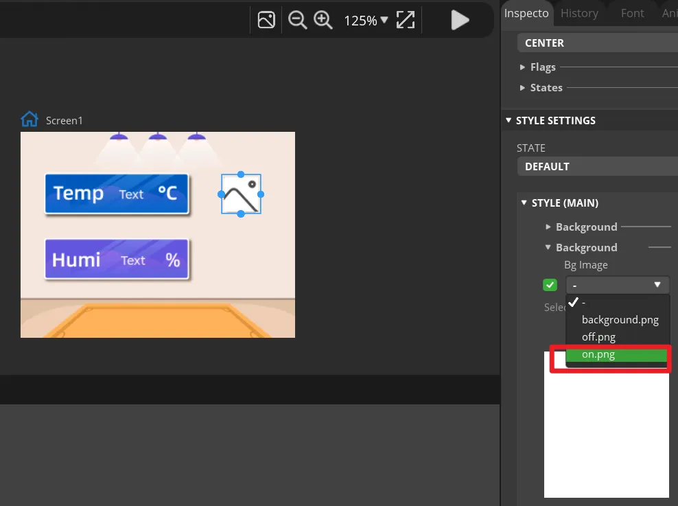
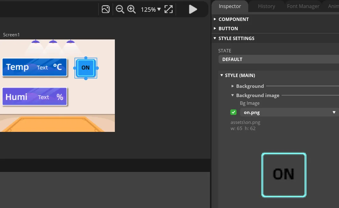
Add an identification symbol to the button. The button in this tutorial controls the LED switch, so you only need to mark the button "on" and "off". You can add LABEL widgets or add a background images to the button. This tutorial will demonstrate how to add a background image to a button.
Click the Button1, then find Inspector->STYLE SETTINGS ->STYLE(MAIN) ->Background, and select the image.
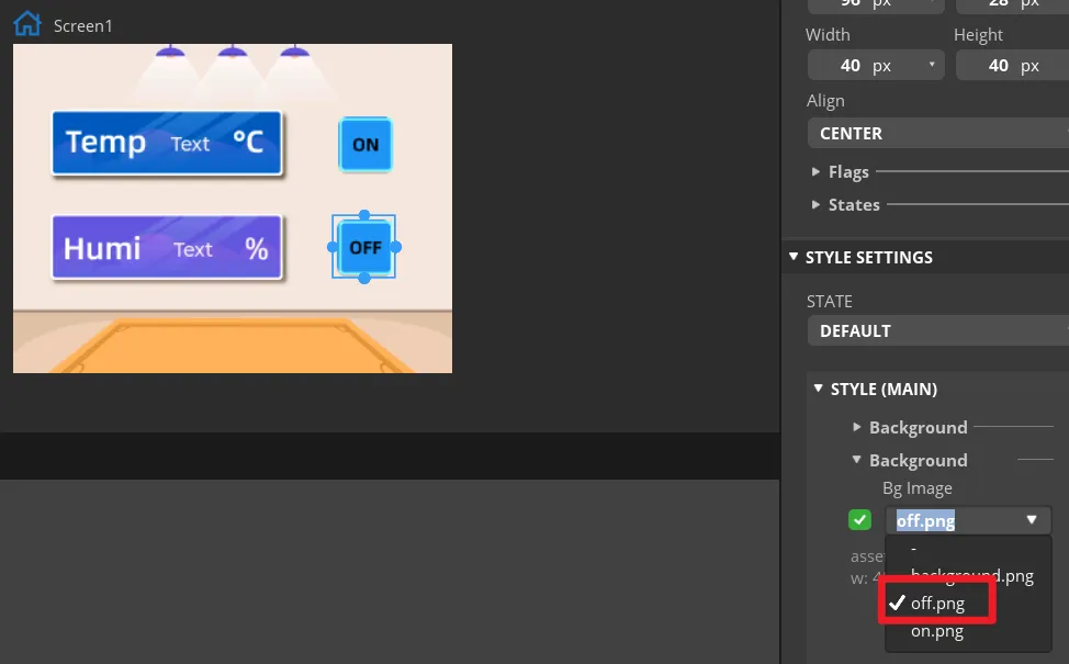
In the same way, duplicate a Button widget. And drag it to the corresponding position to modify different background image.
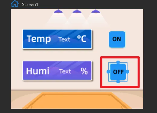
Set the status of the button to identify different states.
In "Inspector"->"STYLE SETTINGS"->"STATE", set display white background color by DEFAULT and red when on the PRESSED state.
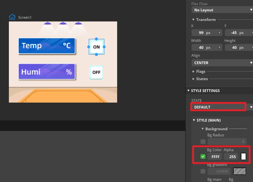
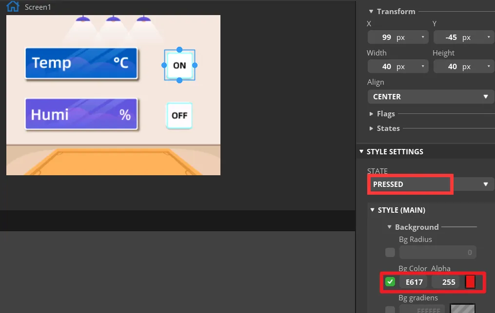
Make the same settings for the "OFF" button.
-
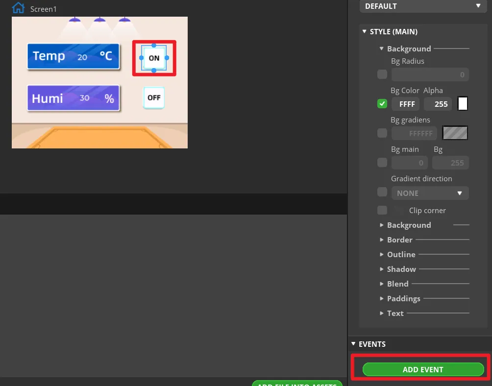
Add events to buttons.
Note: Because the button controls the on and off of the LED, we can add any event here to generate the code framework for the button event when exporting the UI file. We will modify the code of the button event to control the LED latter.
Select the button and click "ADD EVENT".
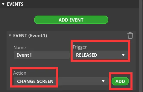
Select "released" as the trigger condition, select a trigger event in "Action". It will be modified in the generated program to achieve the LED control function.
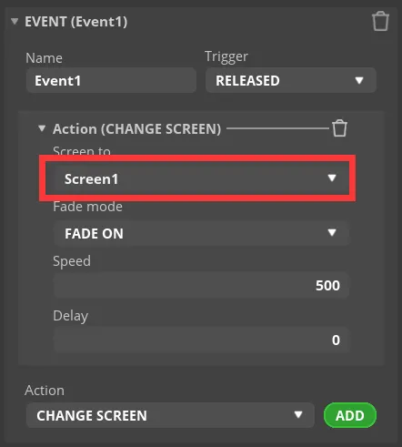
Complete the event. Here I choose to change the screen, and the screen to be switched is Screen1.
Add event to Button2 (OFF) in the same way.
-
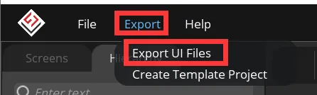
Export UI files.
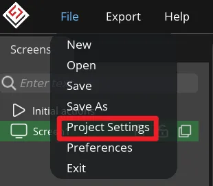
Click "File" -> "Project Settings" and make settings for the exported file.
Set the export path of the file (set the path according to your own file).
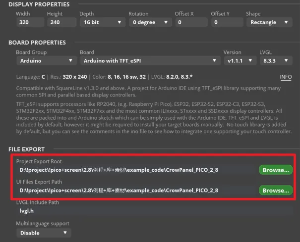
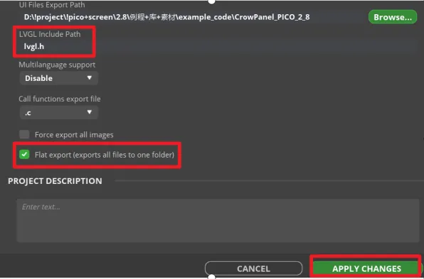
Fill in lvgl.h in LVGL Include Path. Check "Flat export(exports all files to one folder )".
Then click "APPLY CHANGES".
Tips: After selecting the flat export, the output files will be in the same folder, so that the output code does not need to modify the path in the program. If not, the output files will be classified and placed in different folders. The compiler may not be able to recognize different paths, which will cause some trouble. In this case, the user needs to modify it manually, so it is recommended to select all files to be output to the same folder.
Export UI files. The exported files will be in the path we set earlier.
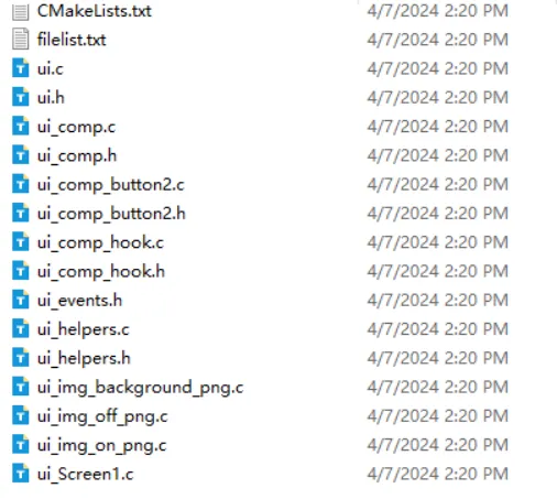
In order to be used with the main program, all UI files generated need to be placed in the same folder as the main program.
Please click
to download the main program(and the expert UI is included).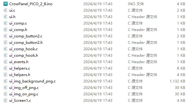
-
Modify the button event code.
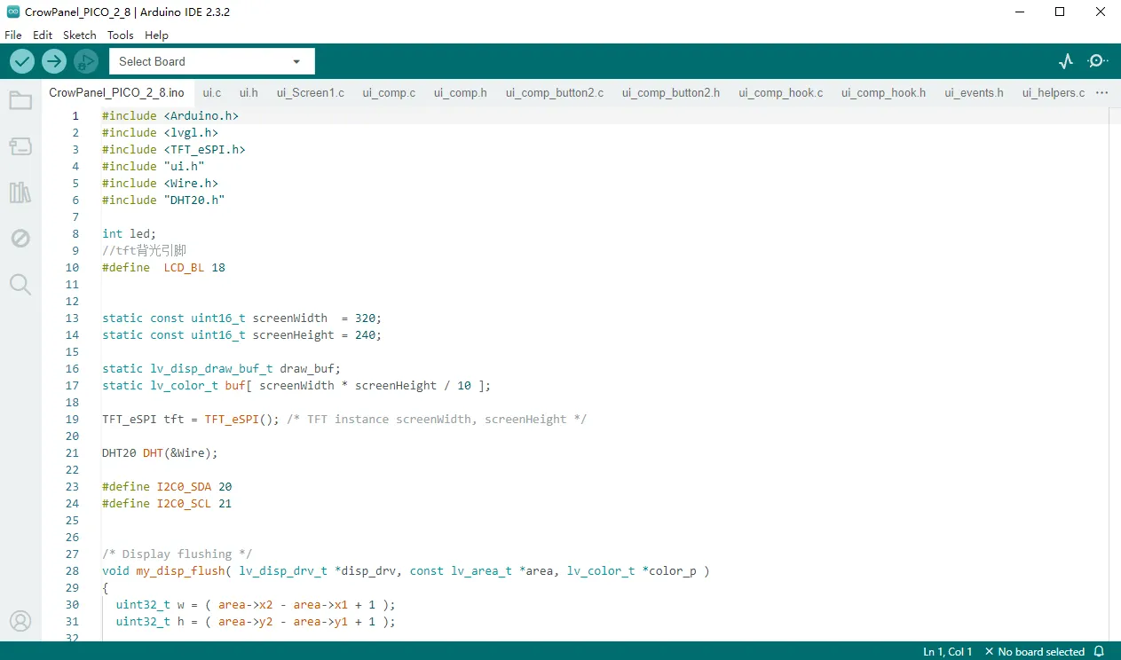
Open the main program. And all the UI file in the same folder will open too.
First, define a variable in the ui.h file to store the status of the LED. In the main program, the LED light is controlled to turn on and off by judging the status of this variable.
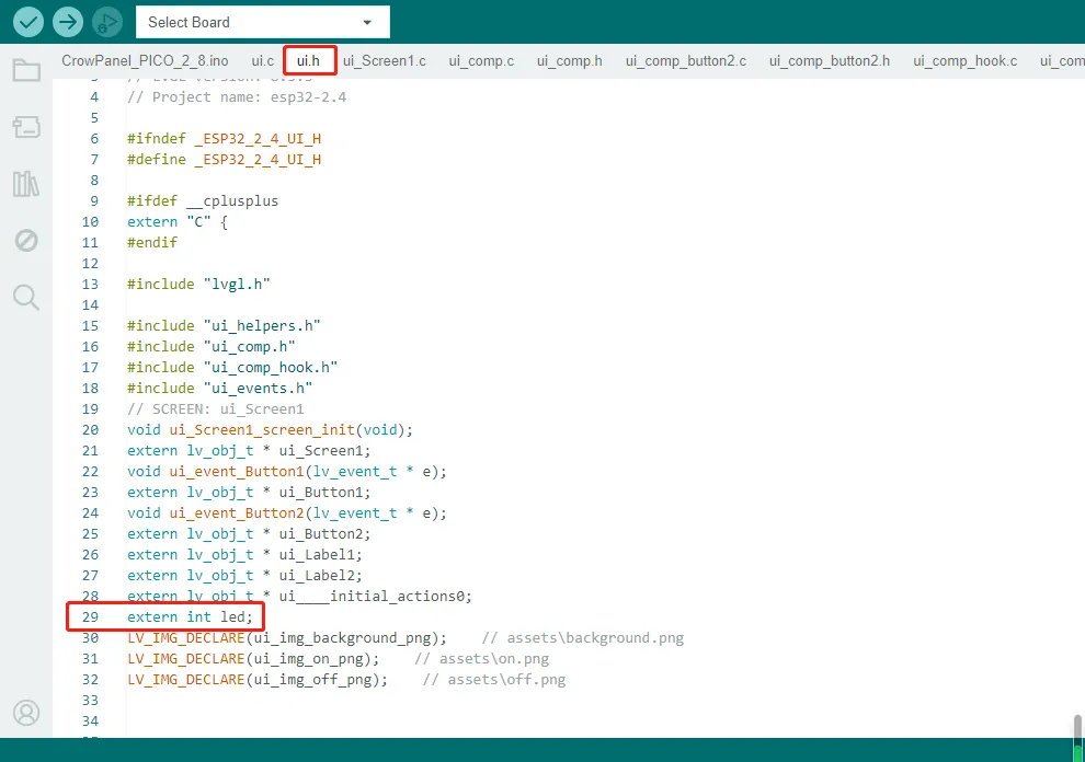
An integer variable named led is declared, and the declaration is defined externally. This means that the variable led is declared here, but its actual definition (memory allocation) is expected to be found elsewhere in the code.
Then find "FUNCTION" in the ui.c file. Here is the corresponding code generated when we add events in SquareLine.
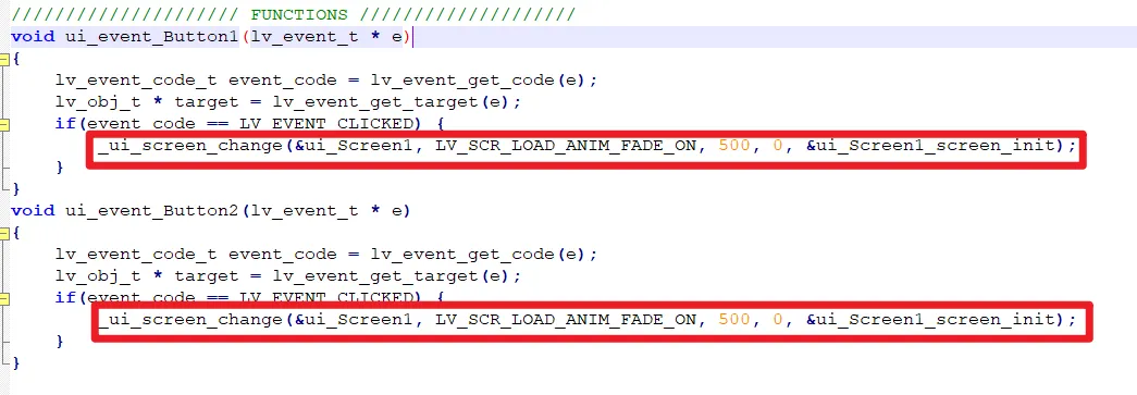
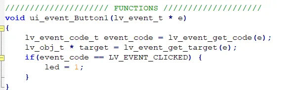
Comment out or delete the code circled in red in the picture above, add new code to assign a value to the LED variable.
- When button 1 (ON button) is pressed, set the LED value to 1.
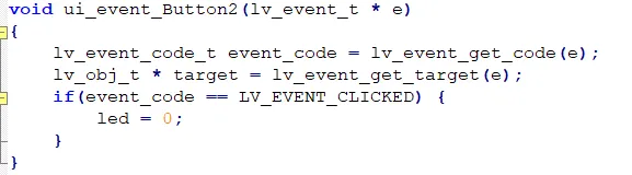
- When button 2 (OFF button) is pressed, set the LED value to 0.
The UI file export is completed, and the button event function is also modified. Next we're going to learn about the Arduino main program and learn how to upload the code to the board.
Build the Project with Arduino IDE
Get Started with Arduino IDE
Please click the card below to learn how to install Arduino IDE, and install RP2040 board in the Arduino IDE.

Add Libraries
In this project, we will use the following libraries:
#include <Arduino.h>
#include <lvgl.h>
#include <TFT_eSPI.h>
#include "ui.h"
#include <Wire.h>
#include "DHT20.h"
#include <Arduino.h>: contains the Arduino core library, providing commonly used functions and data types.#include <lvgl.h>and#include <TFT_eSPI.h>: are libraries for graphical interfaces, used for display control and drawing.- "ui.h": is a custom header file that contain UI-related functions or definitions.
#include <Wire.h>: here we use this library for I2C communication.- "DHT20.h": to read data from the DHT20 temperature and humidity sensor.
Please clickto download the libraries we modified.
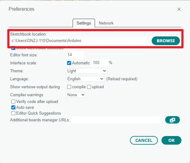
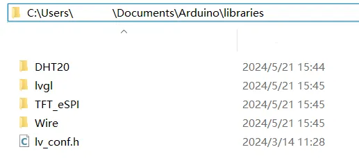
Then click "File" -> "Preferences" -> "Setting" to check the sketchbook location. Place the libraries
downloaded to the sketchbook location.
Tips:
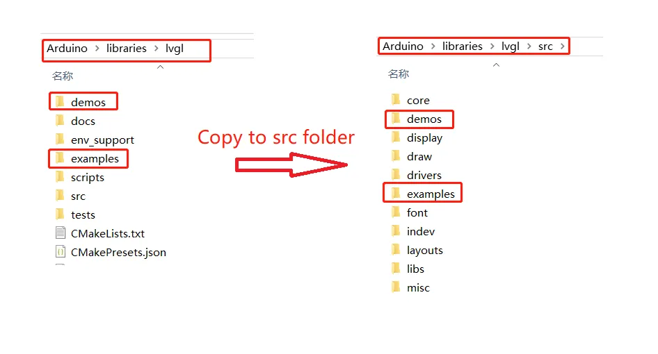
-
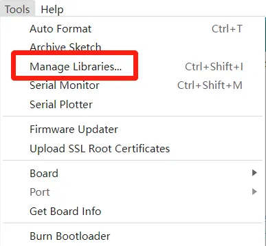
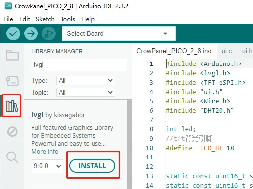
If you install the lvgl libraries by Library Manager, you need to copy the demos folder and examples folder and paste them to src folder. And modify the lv_conf_template.h file and rename it to lv_conf.h, and place it in libraries folder.(Please refer to the library provided)
-
If you install the TFT_eSPI libraries by Library Manager, you need to modify User_Setup.h file accordding to the hardware specification.(Please refer to the library provided)
Code Explanation
Set Up Part
void setup()
{

  Serial.begin( 115200 ); /*Initializing the Serial Port*/

  //IO Port Pins
  pinMode(5, OUTPUT);
   digitalWrite(5, LOW);


 //DHT20 pin setting and initialization. DHT20 use the I2C interface
  Wire.setSDA(I2C0_SDA);
   Wire.setSCL(I2C0_SCL);
   Wire.begin();
   DHT.begin();

 //Set the touch screen calibration data. Obtain the actual data for display
   tft.setTouch(calData);

 //LVGL initialization
  lv_init();


  tft.begin();          /* TFT init */
   tft.setRotation( 1); /* Landscape orientation, flipped */
   tft.fillScreen(TFT_BLACK);


//Screen display initialization, initialize the drawing buffer by calling the lv_disp_draw_buf_init function. This function accepts three parameters: &draw_buf is a pointer to the lv_disp_draw_buf_t structure, buf1 is the buffer used to store pixel data, and the last parameter is NULL to indicate that no additional buffer is used. The buffer size is calculated as screenWidth * screenHeight / 8 and associated with the draw buffer structure.
  lv_disp_draw_buf_init( &draw_buf, buf1, NULL, screenWidth * screenHeight / 8 );

  /*Initializing the display*/
  static lv_disp_drv_t disp_drv;//A static variable disp_drv of type lv_disp_drv_t is defined, which is used to store related configuration and information of the display device driver.
  lv_disp_drv_init( &disp_drv );
  /*Change the following line to display resolution*/
  disp_drv.hor_res = screenWidth;
  disp_drv.ver_res = screenHeight;
  disp_drv.flush_cb = my_disp_flush;
  disp_drv.draw_buf = &draw_buf;
  lv_disp_drv_register( &disp_drv );


//Initialize the (virtual) input device driver. The function of this code is to initialize a virtual input device driver and associate it with the LVGL framework in order to handle the interaction of the input device. Among them, by setting the input device type, defining the read callback function and other steps, the necessary configuration and functions are provided for the input device driver.

  /*Initialize the (virtual) input device driver*/
  static lv_indev_drv_t indev_drv;//Define the input device driver structure

  lv_indev_drv_init( &indev_drv );//Initialize the input device driver

  indev_drv.type = LV_INDEV_TYPE_POINTER;//Setting the input device type

  indev_drv.read_cb = my_touchpad_read;//Define the read callback function

  lv_indev_drv_register( &indev_drv );//Registering Input Device Drivers


tft.fillScreen(TFT_BLACK);
  delay(200);

  pinMode(LCD_BL,OUTPUT);
//  analogWrite(LCD_BL,220);
  digitalWrite(LCD_BL, HIGH);
  delay(100);


//UI initialization
  ui_init();
}
Main Program Part
void loop()
{

//Obtain the temperature and humidity data and use a char array to store it. Use two integer variables a and b to store the obtained temperature and humidity.
  char DHT_buffer[6];
   int status = DHT.read();
  int a = (int)dht20.getTemperature();
  int b = (int)dht20.getHumidity();

//Store the value in an array through conversion and display it on the label
  snprintf(DHT_buffer, sizeof(DHT_buffer), "%d", a);
  lv_label_set_text(ui_Label1, DHT_buffer);
  snprintf(DHT_buffer, sizeof(DHT_buffer), "%d", b);
  lv_label_set_text(ui_Label2, DHT_buffer);

//Determine the value of the LED. In the ui.c program, press the "ON" button to set the LED to 1 and control the LED light to turn on.
  if(led == 1)
  digitalWrite(5, HIGH);

//In the ui.c program, press the "OFF" button to set the LED to 0. At this time, the LED light is controlled to be turned off.
  if(led == 0)
  digitalWrite(5, LOW);

  lv_timer_handler(); /* let the GUI do its work */
  delay( 10 );
}
The Complete Code
#include <Arduino.h>
#include <lvgl.h>
#include <TFT_eSPI.h>
#include "ui.h"
#include <Wire.h>
#include "DHT20.h"

int led;
//tft backlight pin
#define  LCD_BL 18


static const uint16_t screenWidth  = 320;
static const uint16_t screenHeight = 240;

static lv_disp_draw_buf_t draw_buf;
static lv_color_t buf[ screenWidth * screenHeight / 10 ];

TFT_eSPI tft = TFT_eSPI(); /* TFT instance screenWidth, screenHeight */

DHT20 DHT(&Wire);

#define I2C0_SDA 20
#define I2C0_SCL 21


/* Display flushing */
void my_disp_flush( lv_disp_drv_t *disp_drv, const lv_area_t *area, lv_color_t *color_p )
{
  uint32_t w = ( area->x2 - area->x1 + 1 );
  uint32_t h = ( area->y2 - area->y1 + 1 );

  tft.startWrite();
  tft.setAddrWindow( area->x1, area->y1, w, h );
  tft.pushColors( ( uint16_t * )&color_p->full, w * h, true );
  tft.endWrite();

  lv_disp_flush_ready( disp_drv );
}

uint16_t touchX, touchY;
/*Read Touchpad*/
void my_touchpad_read( lv_indev_drv_t * indev_driver, lv_indev_data_t * data )
{
//  data->state = LV_INDEV_STATE_REL;
  bool touched = tft.getTouch( &touchX, &touchY, 600);
  if ( !touched )
  {
    data->state = LV_INDEV_STATE_REL;
  }
  else
  {
    data->state = LV_INDEV_STATE_PR;

    /*Setting the coordinates*/
    data->point.x = touchX;
    data->point.y = touchY;

    Serial1.print( "Data x " );
    Serial1.println( touchX );

    Serial1.print( "Data y " );
    Serial1.println(  touchY);

  }
}


uint16_t calData[5] = { 208, 3520, 380, 3373, 1 };


void setup()
{

  Serial.begin( 115200 );


  //IO Port Pins
  pinMode(5, OUTPUT);
  digitalWrite(5, LOW);

  Wire.setSDA(I2C0_SDA);
  Wire.setSCL(I2C0_SCL);
  Wire.begin();
  DHT.begin();


  /*Set the touchscreen calibration data,
    the actual data for your display can be acquired using
    the Generic -> Touch_calibrate example from the TFT_eSPI library*/
  tft.setTouch(calData);

  lv_init();

  tft.begin();          /* TFT init */
  tft.setRotation( 1); /* Landscape orientation, flipped */
  tft.fillScreen(TFT_BLACK);

// #if LV_USE_LOG != 0
//   lv_log_register_print_cb( my_print ); /* register print function for debugging */
// #endif

  lv_disp_draw_buf_init( &draw_buf, buf, NULL, screenWidth * screenHeight / 10 );

  /*Initialize the display*/
  static lv_disp_drv_t disp_drv;
  lv_disp_drv_init( &disp_drv );
  /*Change the following line to your display resolution*/
  disp_drv.hor_res = screenWidth;
  disp_drv.ver_res = screenHeight;
  disp_drv.flush_cb = my_disp_flush;
  disp_drv.draw_buf = &draw_buf;
  lv_disp_drv_register( &disp_drv );

  /*Initialize the (dummy) input device driver*/
      static lv_indev_drv_t indev_drv;
      lv_indev_drv_init( &indev_drv );
      indev_drv.type = LV_INDEV_TYPE_POINTER;
      indev_drv.read_cb = my_touchpad_read;
      lv_indev_drv_register( &indev_drv );

  tft.fillScreen(TFT_BLACK);
  delay(200);

  pinMode(LCD_BL,OUTPUT);
//  analogWrite(LCD_BL,220);
  digitalWrite(LCD_BL, HIGH);
  delay(100);

   ui_init();
}

void loop()
{

  char DHT_buffer[6];

  int status = DHT.read();

  int a = (int)DHT.getTemperature();
  int b = (int)DHT.getHumidity();
  snprintf(DHT_buffer, sizeof(DHT_buffer), "%d", a);
  lv_label_set_text(ui_Label1, DHT_buffer);
  snprintf(DHT_buffer, sizeof(DHT_buffer), "%d", b);
  lv_label_set_text(ui_Label2, DHT_buffer);


  if(led == 1)

  digitalWrite(5, HIGH);
  if(led == 0)
  digitalWrite(5, LOW);
  lv_timer_handler(); /* let the GUI do its work */
  delay( 10 );

}
Upload the Code
-
After completing the installation of the RP2040 board according to "Get Started with Arduino IDE" and the installation of the library according to "Add Libraries", open the program and connect the PICO HMI 2.8-inch to the computer via a USB-C cable.
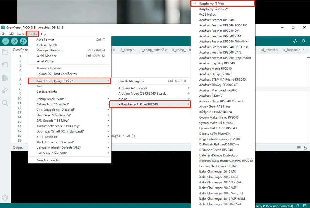
-
Select Board: click "Tools" -> "Board" -> "Raspberry Pi Pico/RP2040" and select "Raspberry Pi Pico"
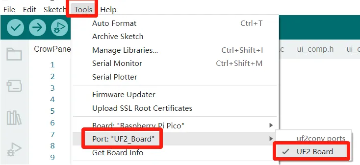
-
Select Port: Please hold the BOOT button and press the RESET button first, and the PICO HMI board will turn into a U disk. Then click "Tools" -> "Port" and select UF2...(Note: you need to press the button every time you need to connect the board with computer through serial communication.)
-
Upload the code
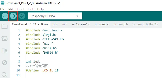
-
After the program is successfully uploaded, connect the DHT20 sensor to the IIC port and the LED to UART1 (GP5).
Click the RESET button, and the temperature and humidity values will be displayed on the screen. Click the ON button on the screen and the LED will turn on. Click the OFF button and the LED will turn off.
Example Demo of PICO HMI Function
Example1: LED blinking.
Connect the LED to UART1(GP5) port, and upload the following code to the board. The LED will blinking.
#define D_PIN 5

void setup() {
  // put your setup code here, to run once:
  Serial.begin(115200);
  pinMode(D_PIN, OUTPUT);
}

void loop() {
  // put your main code here, to run repeatedly:
  digitalWrite(D_PIN, HIGH);
  delay(500);
  digitalWrite(D_PIN, LOW);
  delay(500);
}
Example2: Monitor environment temperature and humidity
Connect the DHT20 sensor to IIC port. After uploading the code to the board, the temperature and humidity value will show on serial monitor.
#include <Arduino.h>

#include <TFT_eSPI.h>

#include <Wire.h>
#include "DHT20.h"


DHT20 DHT(&Wire);

#define I2C0_SDA 20
#define I2C0_SCL 21

void setup()
{

  Serial.begin( 115200 );


  Wire.setSDA(I2C0_SDA);
  Wire.setSCL(I2C0_SCL);
  Wire.begin();
  DHT.begin();


  delay(100);

}

void loop()
{

  char DHT_buffer[6];

  int status = DHT.read();

  int a = (int)DHT.getTemperature();
  int b = (int)DHT.getHumidity();
  Serial.print("Temperature:");
  Serial.println(a);
  Serial.print("getHumidity:");
  Serial.println(b);

  delay( 500 );

}
Example3: Initialize TF Card slot
#include <Wire.h>
#include <SPI.h>
#include <SD.h>
#include <FS.h>

const int _MISO = 12;  // AKA SPI RX
const int _MOSI = 11;  // AKA SPI TX
const int _CS = 22;
const int _SCK = 10;
File root;

void setup() {
  // put your setup code here, to run once:
  Serial.begin( 9600 ); /*初始化串口*/
  //SD卡
  // SPI.begin(SD_SCK, SD_MISO, SD_MOSI);
  // delay(100);
  // if (SD_init() == 1)
  // {
  //   Serial.println("Card Mount Failed");
  // }
  // else
  //   Serial.println("initialize SD Card successfully");
}

void loop() {
  Serial1.println("\nInitializing SD card...");
  Serial.println("\nInitializing SD card...");
  bool sdInitialized = false;
  // Ensure the SPI pinout the SD card is connected to is configured properly
  // Select the correct SPI based on _MISO pin for the RP2040
  if (_MISO == 0 || _MISO == 4 || _MISO == 16) {
    SPI.setRX(_MISO);
    SPI.setTX(_MOSI);
    SPI.setSCK(_SCK);
    sdInitialized = SD.begin(_CS);
  } else if (_MISO == 8 || _MISO == 12) {
    SPI1.setRX(_MISO);
    SPI1.setTX(_MOSI);
    SPI1.setSCK(_SCK);
    sdInitialized = SD.begin(_CS, SPI1);
  } else {
    Serial.println(F("ERROR: Unknown SPI Configuration"));
    Serial1.println(F("ERROR: Unknown SPI Configuration"));
    return;
  }

  if (!sdInitialized) {
    Serial1.println("initialization failed. Things to check:");
    Serial1.println("* is a card inserted?");
    Serial1.println("* is your wiring correct?");
    Serial1.println("* did you change the chipSelect pin to match your shield or module?");

    Serial.println("initialization failed. Things to check:");
    Serial.println("* is a card inserted?");
    Serial.println("* is your wiring correct?");
    Serial.println("* did you change the chipSelect pin to match your shield or module?");
    return;
  } else {
    Serial1.println("Wiring is correct and a card is present.");
    Serial.println("Wiring is correct and a card is present.");
  }
  // 0 - SD V1, 1 - SD V2, or 3 - SDHC/SDXC
  // print the type of card
  Serial1.println();
  Serial1.print("Card type:         ");
  Serial.println();
  Serial.print("Card type:         ");
  switch (SD.type()) {
    case 0:
      Serial1.println("SD1");
      Serial.println("SD1");
      break;
    case 1:
      Serial1.println("SD2");
      Serial.println("SD2");
      break;
    case 3:
      Serial1.println("SDHC/SDXC");
      Serial.println("SDHC/SDXC");
      break;
    default:
      Serial1.println("Unknown");
      Serial.println("Unknown");
  }

  Serial1.print("Cluster size:          ");
  Serial1.println(SD.clusterSize());
  Serial1.print("Blocks x Cluster:  ");
  Serial1.println(SD.blocksPerCluster());
  Serial1.print("Blocks size:  ");
  Serial1.println(SD.blockSize());

  Serial.print("Cluster size:          ");
  Serial.println(SD.clusterSize());
  Serial.print("Blocks x Cluster:  ");
  Serial.println(SD.blocksPerCluster());
  Serial.print("Blocks size:  ");
  Serial.println(SD.blockSize());

  Serial1.print("Total Blocks:      ");
  Serial1.println(SD.totalBlocks());
  Serial1.println();

  Serial.print("Total Blocks:      ");
  Serial.println(SD.totalBlocks());
  Serial.println();

  Serial1.print("Total Cluster:      ");
  Serial1.println(SD.totalClusters());
  Serial1.println();

  Serial.print("Total Cluster:      ");
  Serial.println(SD.totalClusters());
  Serial.println();

  // print the type and size of the first FAT-type volume
  uint32_t volumesize;
  Serial1.print("Volume type is:    FAT");
  Serial1.println(SD.fatType(), DEC);

  Serial.print("Volume type is:    FAT");
  Serial.println(SD.fatType(), DEC);

  volumesize = SD.totalClusters();
  volumesize *= SD.clusterSize();
  volumesize /= 1000;
  Serial1.print("Volume size (Kb):  ");
  Serial1.println(volumesize);
  Serial1.print("Volume size (Mb):  ");

  Serial.print("Volume size (Kb):  ");
  Serial.println(volumesize);
  Serial.print("Volume size (Mb):  ");
  volumesize /= 1024;
  Serial1.println(volumesize);
  Serial1.print("Volume size (Gb):  ");
  Serial1.println((float)volumesize / 1024.0);

  Serial.println(volumesize);
  Serial.print("Volume size (Gb):  ");
  Serial.println((float)volumesize / 1024.0);

  Serial1.print("Card size:  ");
  Serial1.println((float)SD.size() / 1000);

  Serial.print("Card size:  ");
  Serial.println((float)SD.size() / 1000);
  FSInfo fs_info;
  SDFS.info(fs_info);

  Serial1.print("Total bytes: ");
  Serial1.println(fs_info.totalBytes);

  Serial1.print("Used bytes: ");
  Serial1.println(fs_info.usedBytes);

  Serial.print("Total bytes: ");
  Serial.println(fs_info.totalBytes);

  Serial.print("Used bytes: ");
  Serial.println(fs_info.usedBytes);
  root = SD.open("/");
  printDirectory(root, 0);

}
void printDirectory(File dir, int numTabs) {
  while (true) {

    File entry = dir.openNextFile();
    if (!entry) {
      // no more files
      break;
    }
    for (uint8_t i = 0; i < numTabs; i++) {
      Serial1.print('\t');
      Serial.print('\t');
    }
    Serial1.print(entry.name());
    Serial.print(entry.name());
    if (entry.isDirectory()) {
      Serial1.println("/");
      Serial.println("/");
      printDirectory(entry, numTabs + 1);
    } else {
      // files have sizes, directories do not
      Serial1.print("\t\t");
      Serial1.print(entry.size(), DEC);
      Serial.print("\t\t");
      Serial.print(entry.size(), DEC);
      time_t cr = entry.getCreationTime();
      time_t lw = entry.getLastWrite();
      struct tm* tmstruct = localtime(&cr);
      Serial1.printf("\tCREATION: %d-%02d-%02d %02d:%02d:%02d", (tmstruct->tm_year) + 1900, (tmstruct->tm_mon) + 1, tmstruct->tm_mday, tmstruct->tm_hour, tmstruct->tm_min, tmstruct->tm_sec);
      Serial.printf("\tCREATION: %d-%02d-%02d %02d:%02d:%02d", (tmstruct->tm_year) + 1900, (tmstruct->tm_mon) + 1, tmstruct->tm_mday, tmstruct->tm_hour, tmstruct->tm_min, tmstruct->tm_sec);
      tmstruct = localtime(&lw);
      Serial.printf("\tLAST WRITE: %d-%02d-%02d %02d:%02d:%02d\n", (tmstruct->tm_year) + 1900, (tmstruct->tm_mon) + 1, tmstruct->tm_mday, tmstruct->tm_hour, tmstruct->tm_min, tmstruct->tm_sec);
      Serial1.printf("\tLAST WRITE: %d-%02d-%02d %02d:%02d:%02d\n", (tmstruct->tm_year) + 1900, (tmstruct->tm_mon) + 1, tmstruct->tm_mday, tmstruct->tm_hour, tmstruct->tm_min, tmstruct->tm_sec);
    }
    entry.close();
  }

}
Example4: Initialize the touch
#include <TFT_eSPI.h>
TFT_eSPI lcd = TFT_eSPI(); /* TFT example */
uint16_t touchX, touchY;
uint16_t calData[5] = { 208, 3520, 380, 3373, 1 };

void setup() {
  // put your setup code here, to run once:
  Serial.begin( 9600 ); /*Initializing serial port*/
  //Initializing LCD
  lcd.begin();
  lcd.setRotation(1); /* Rotate */
  //Calibration mode. One is four corner positioning, and the other is direct input analog value direct positioning
  //Screen calibration
//  touch_calibrate();
  lcd.setTouch(calData);

  /*Initializing*/
}

void loop() {
  // put your main code here, to run repeatedly:
  bool touched = lcd.getTouch( &touchX, &touchY, 600);
  if ( touched )
  {
    Serial.print( "Data x " );
    Serial.println( touchX );

    Serial.print( "Data y " );
    Serial.println( touchY );
  }
}

void touch_calibrate()//Screen calibration
{
  uint16_t calData[5];
  uint8_t calDataOK = 0;
  Serial.println("Screen calibration");

  //calibration
  Serial.println("Touch the corner as directed");

 // lv_timer_handler();
  lcd.calibrateTouch(calData, TFT_MAGENTA, TFT_BLACK, 15);
  Serial.println("calibrateTouch(calData, TFT_MAGENTA, TFT_BLACK, 15)");
  Serial.println(); Serial.println();
  Serial.println("//Use this calibration code in setup():");
  Serial.print("uint16_t calData[5] = ");
  Serial.print("{ ");

  for (uint8_t i = 0; i < 5; i++)
  {
    Serial.print(calData[i]);
    if (i < 4) Serial.print(", ");
  }

  Serial.println(" };");
  Serial.print("  tft.setTouch(calData);");
  Serial.println(); Serial.println();


}
Example5: UART
//at 9600 bps 8-N-1

#include <SoftwareSerial.h>

SoftwareSerial SoftSerial(6, 7);
unsigned char buffer[256]; // buffer array for data recieve over serial port
int count=0;     // counter for buffer array
void setup()
{
  SoftSerial.begin(9600);               // the SoftSerial baud rate
  Serial.begin(9600);             // the Serial port of Arduino baud rate.

}

void loop()
{
  if (SoftSerial.available())              // if date is comming from softwareserial port ==> data is comming from SoftSerial shield
  {
    while(SoftSerial.available())          // reading data into char array
    {
      buffer[count++]=SoftSerial.read();     // writing data into array
      if(count == 256)break;
  }
    Serial.write(buffer,count);            // if no data transmission ends, write buffer to hardware serial port
    clearBufferArray();              // call clearBufferArray function to clear the storaged data from the array
    count = 0;                       // set counter of while loop to zero


  }
  if (Serial.available())            // if data is available on hardwareserial port ==> data is comming from PC or notebook
    SoftSerial.write(Serial.read());       // write it to the SoftSerial shield
}
void clearBufferArray()              // function to clear buffer array
{
  for (int i=0; i<count;i++)
    { buffer[i]=NULL;}                  // clear all index of array with command NULL
}