PICO W5 Tutorial
Over All
This tutorial demonstrates how to connect the PICO W5 development board to the Home Assistant server on the Arduino IDE and Thonny IDE platforms, and display the temperature and humidity on the server terminal.
In addition, there are examples to demonstrate how to use the GPIO, I2C, UART, PWM and other pins of the PICO W5 development board.
Home Assistant Server Configuration
Install Home Assistant OS
-
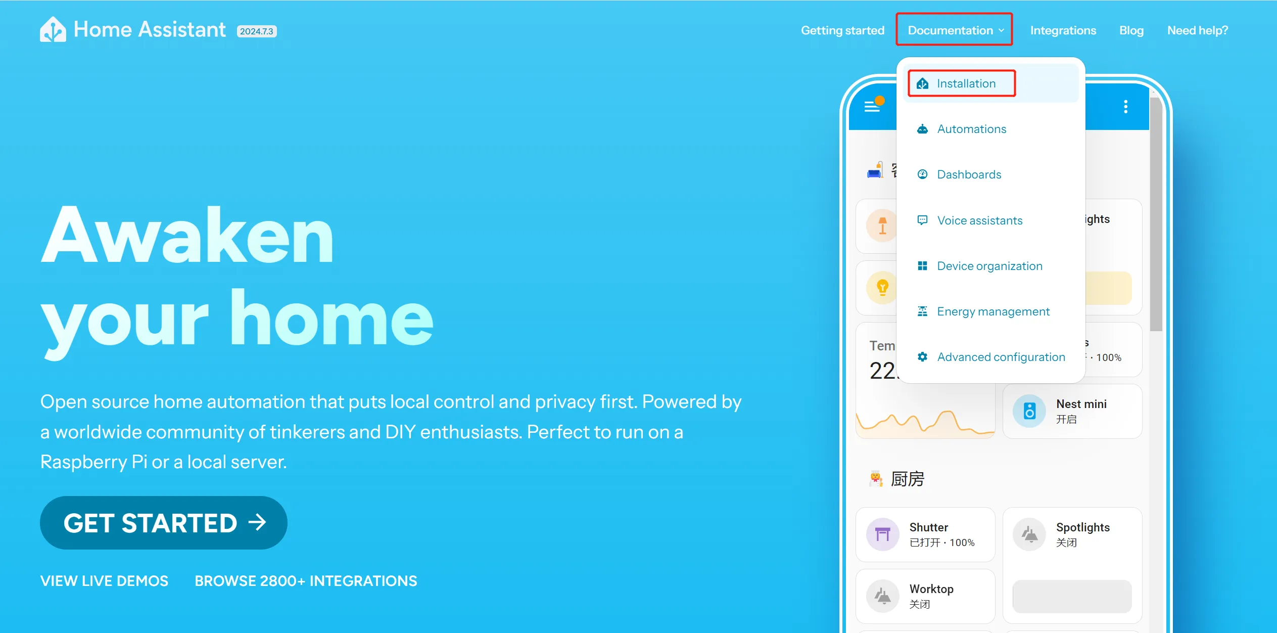
Go to https://www.home-assistant.io/, and click the "Installation" under "Documentation" on the homepage.
-
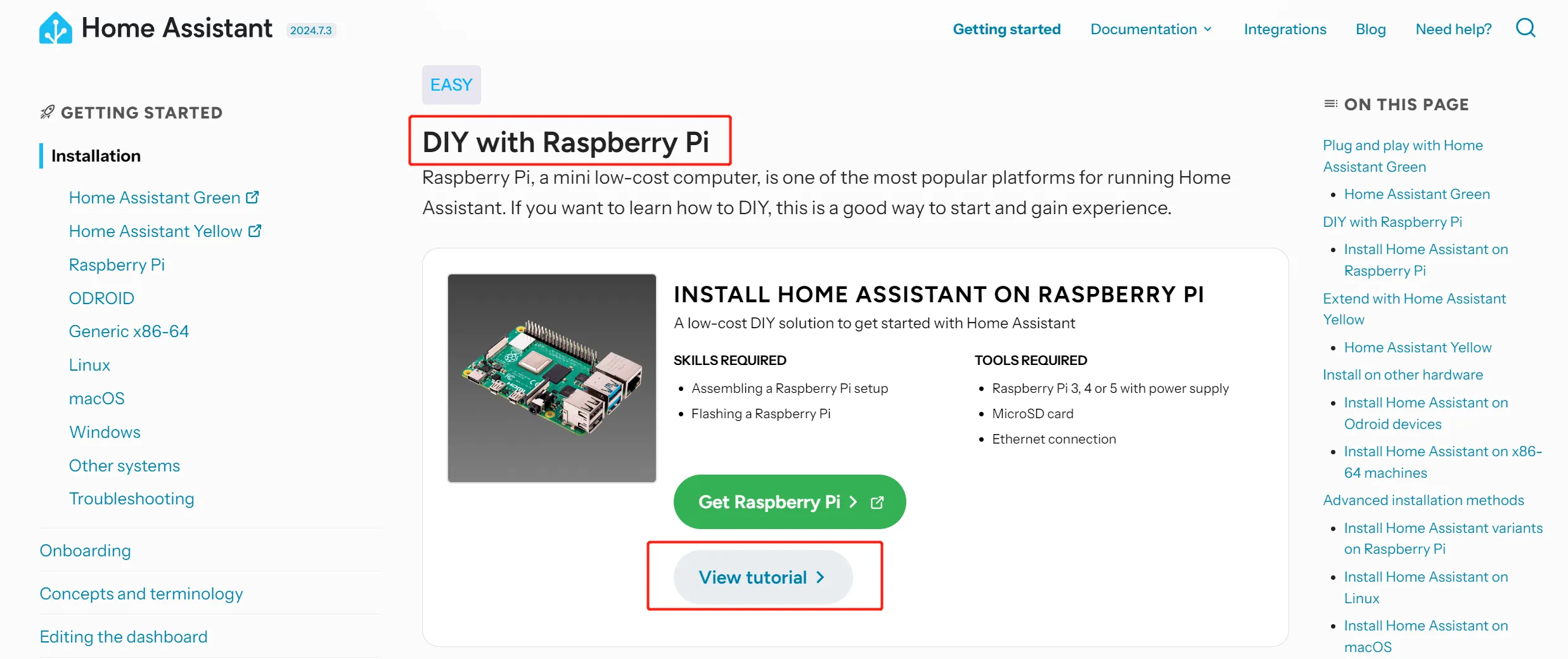
Scroll down to the "DIY with Raspberry Pi" section, and click "View tutorial".
-
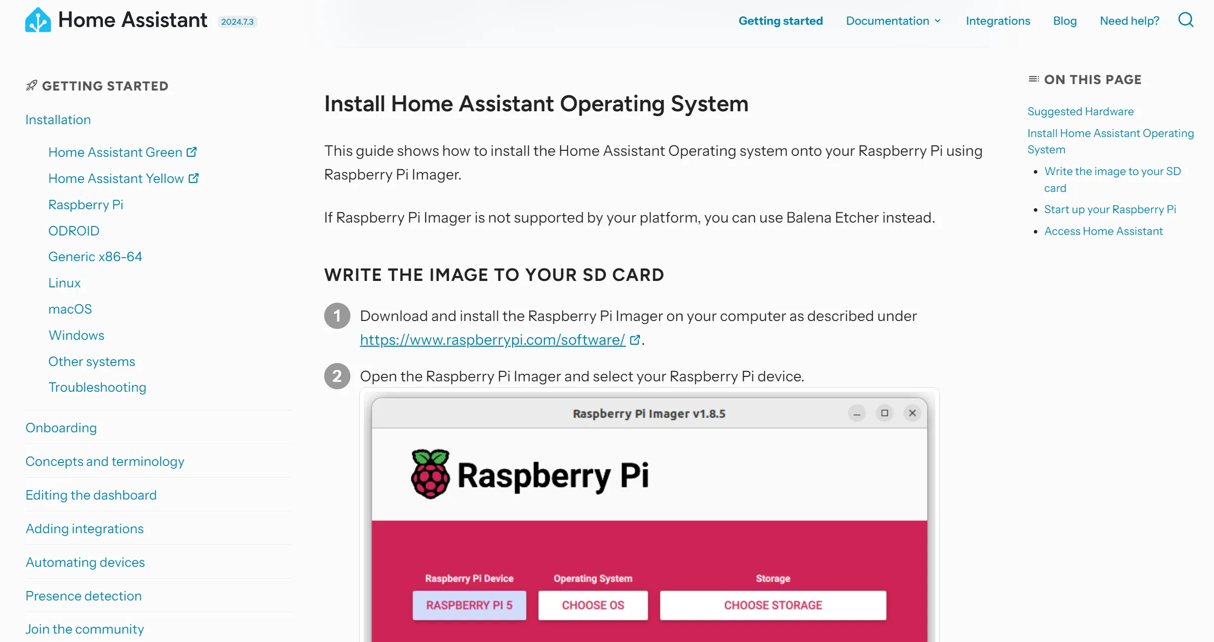
Follow the Home Assistant tutorial to install Operating System.
-
Eject the SD card after the Home Assistant OS is written.
-
Start up your Raspberry Pi.
- Insert the SD card into your Raspberry Pi.
- Plug in an Ethernet cable and make sure the Raspberry Pi is connected to the same network as your computer and is connected to the Internet.
- Connect the power supply to start up the device.
Register for Home Assistant
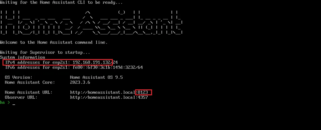
Within a few minutes after connecting the Raspberry Pi, you will be able to reach your new Home Assistant.
-
In the browser of your desktop system, enter homeassistant.local:8123.

Note
If you are running an older Windows version or have a stricter network configuration, you might need to access Home Assistant at homeassistant:8123 or
http://X.X.X.X:8123(replace X.X.X.X with your Raspberry Pi’s IP address).The time it takes for this page to become available depends on your hardware. On a Raspberry Pi 4 or 5, this page should be available within a minute.
- If it does not show up after 5 minutes on a Pi 4 or 5, maybe the image was not written properly.
- Try to flash the SD card again, possibly even try a different SD card.
- If this did not help, view the console output on the Raspberry Pi.
- To do this, connect a monitor via HDMI.
-
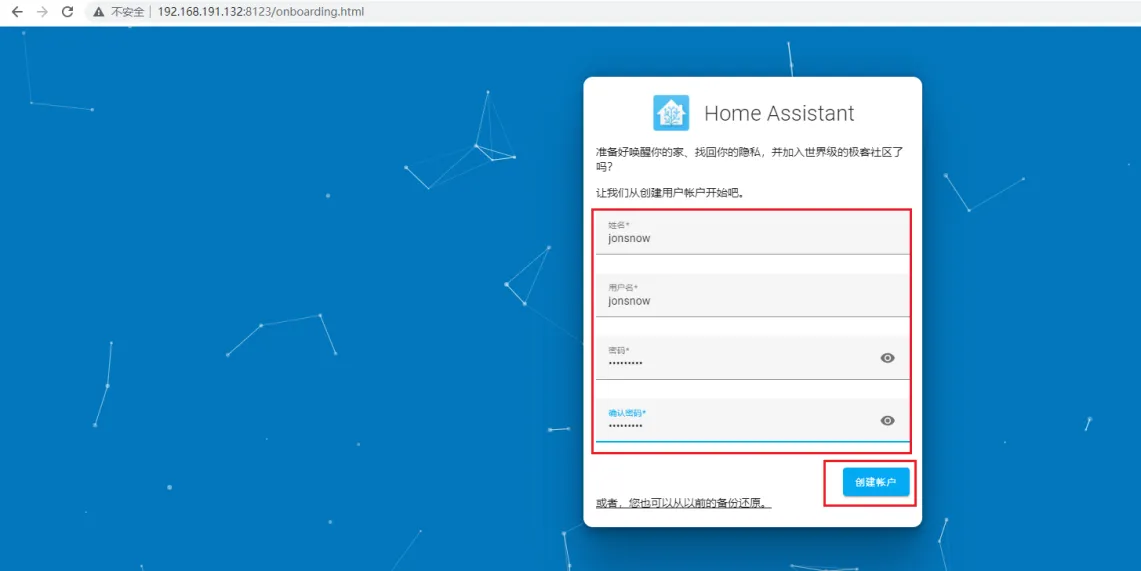
For the first visit, you need to create an account. Fill in the username and password, and create an account.
-
Region selection. You can manually locate or select automatic detection.
-
Next, click Next by default.
-
Then click Finish. It will prompt you to add a smart device. You can click Finish first and then set it up yourself.
-
Then enter the control panel interface
Access Home Assistant and Set MQTT
Note: The Raspberry Pi and the computer need to be in the same LAN (same network).
-
In the browser of your desktop system, enter homeassistant.local:8123.
-
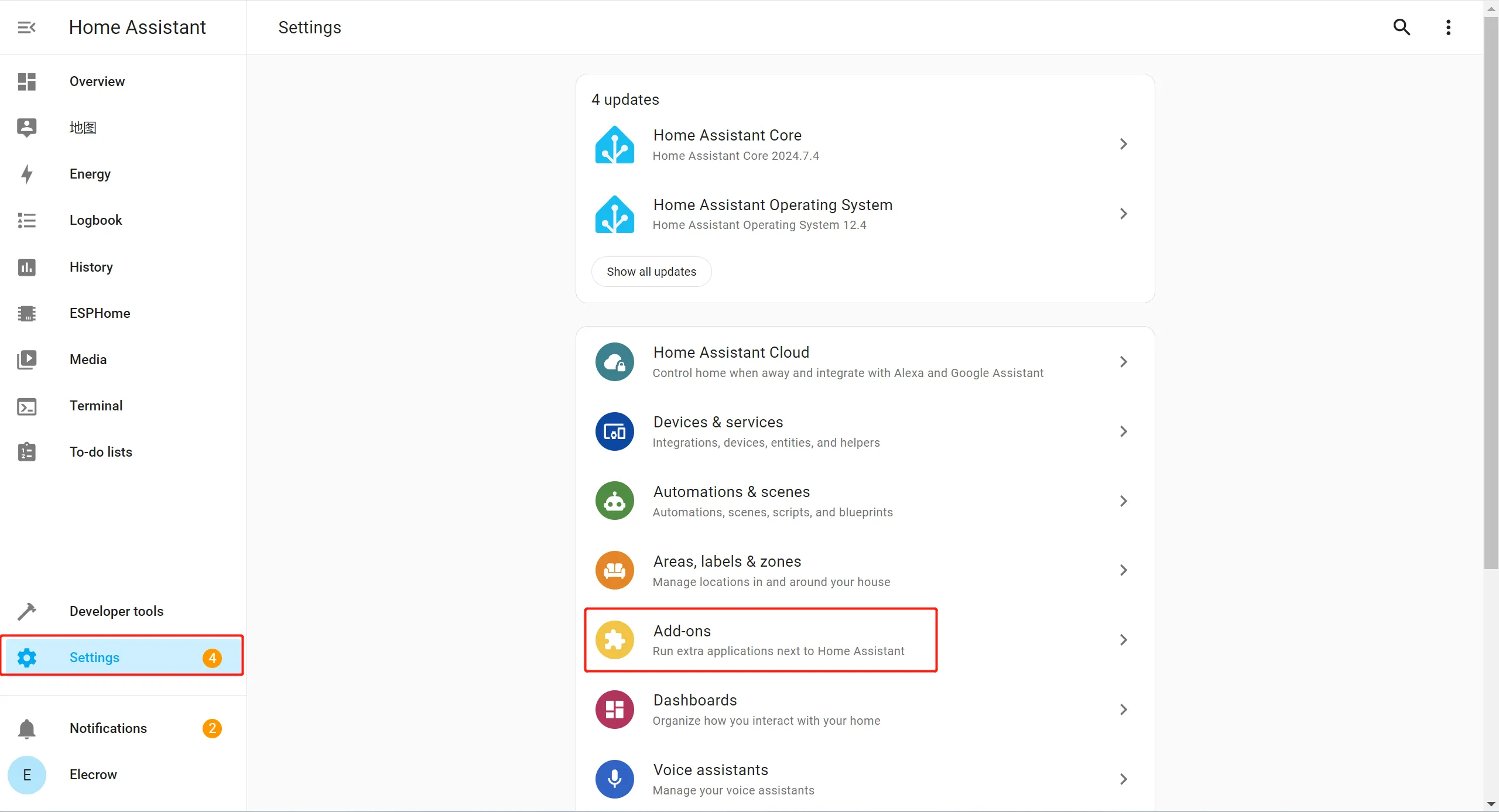
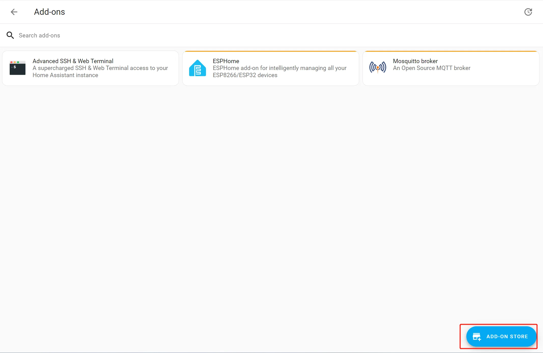
Click "Setting" -> "Add on"
-
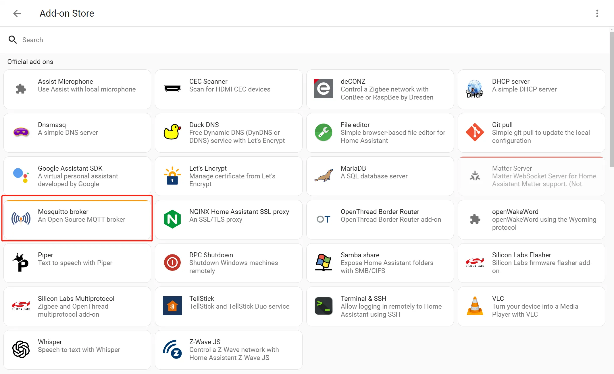
Click ADD-ON STORE
-
Select "Mosquitto broker" and install
-
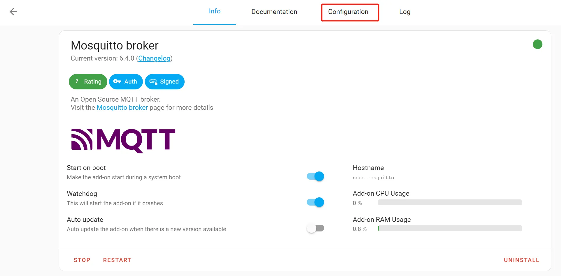
Enable Mosquitto broker
-
Then click "Configuration" -> "Options" -> "Logins", and set the username and password.
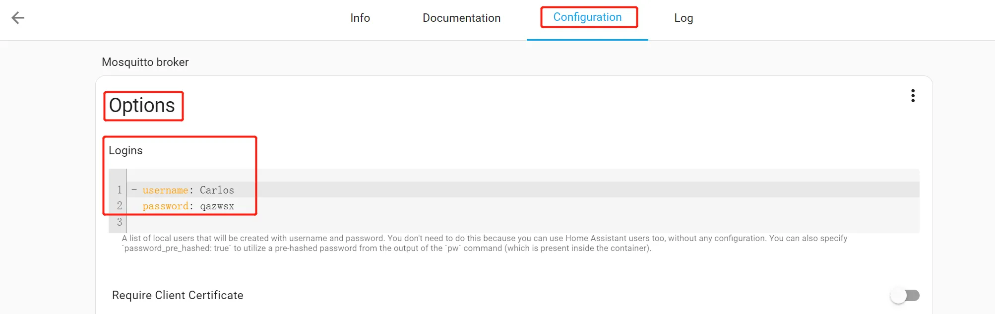
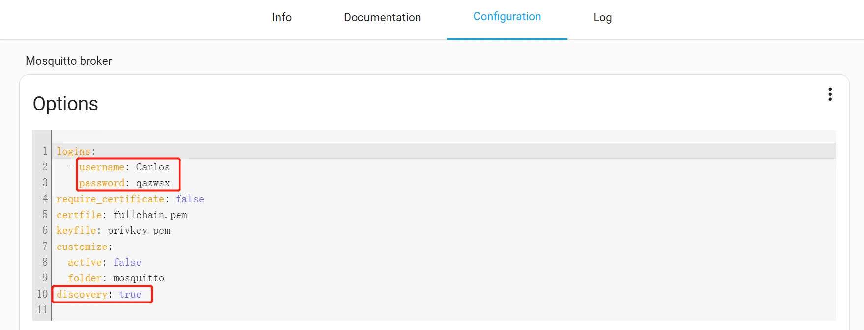
Click the three-dot icon, then click "Edit in YAML"
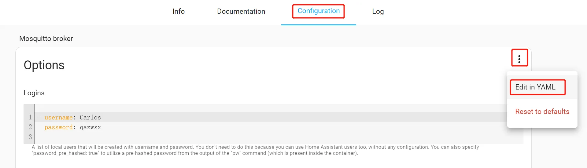
Modify the username and password, and set the discovery to "true".
-
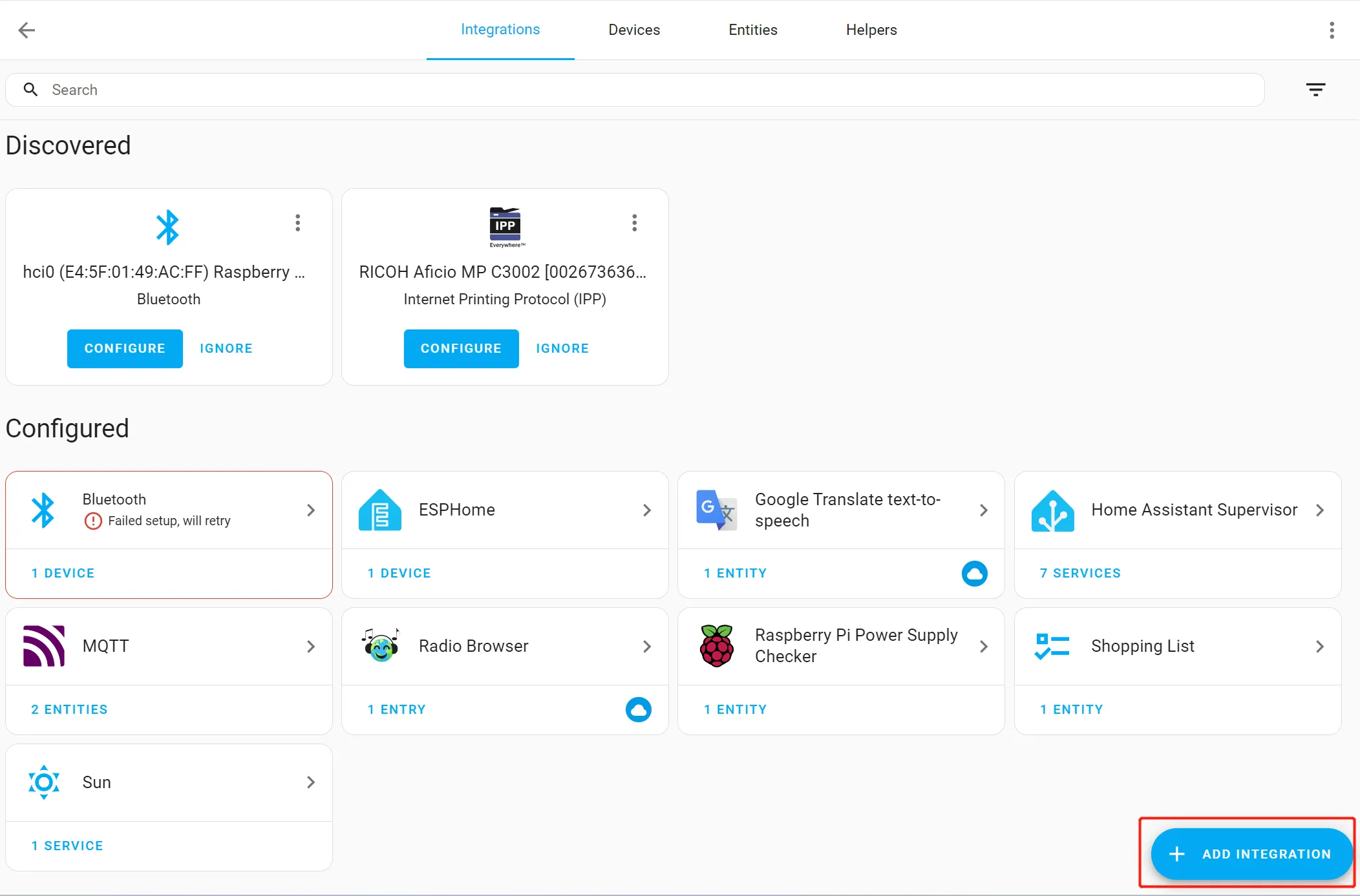
Click "Setting"-> "Devices&Service"

-
Click "ADD INTEGRATION"
-
Search for "MQTT"
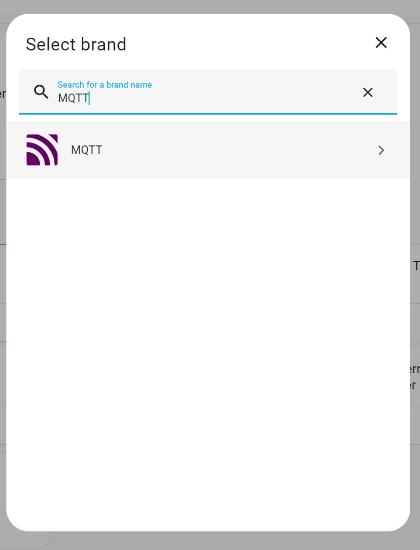
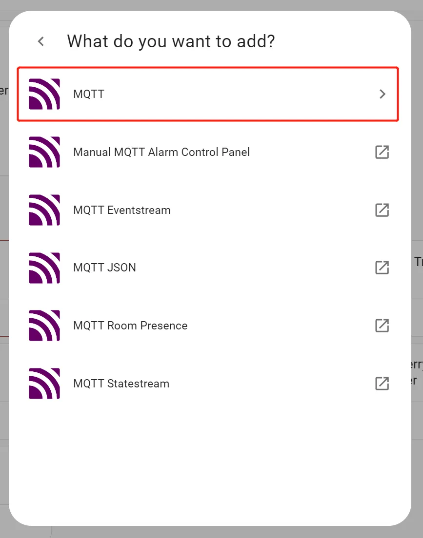
-
Configure the MQTT server information (the server address is the address and port number of the Raspberry Pi server, and the username and password are the username and password configured in step 6)
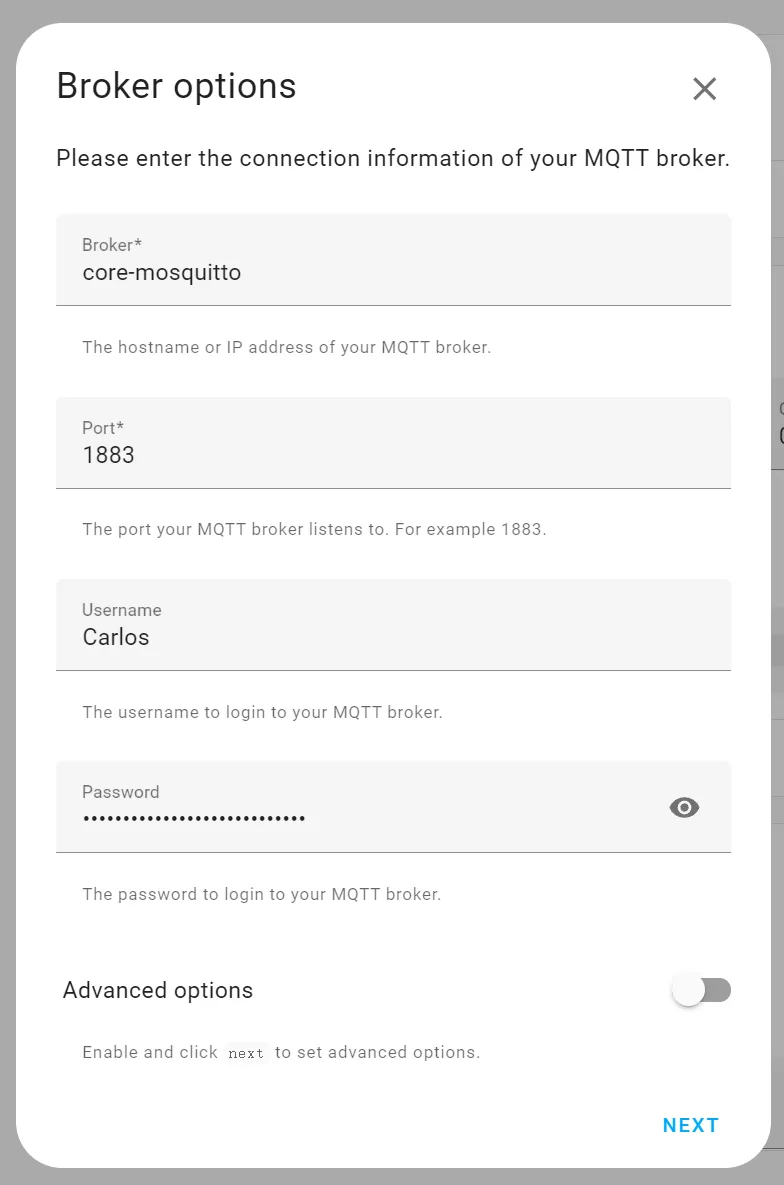
-
Click "Setting" -> "Add on" -> "ADD-ON STORE", and install Samba share
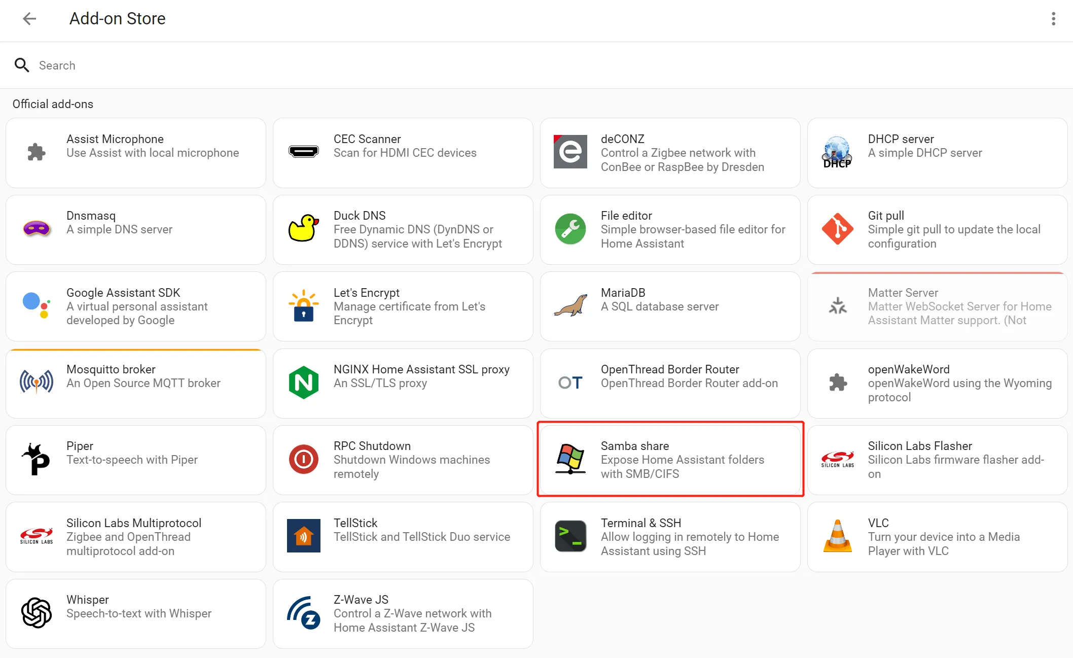
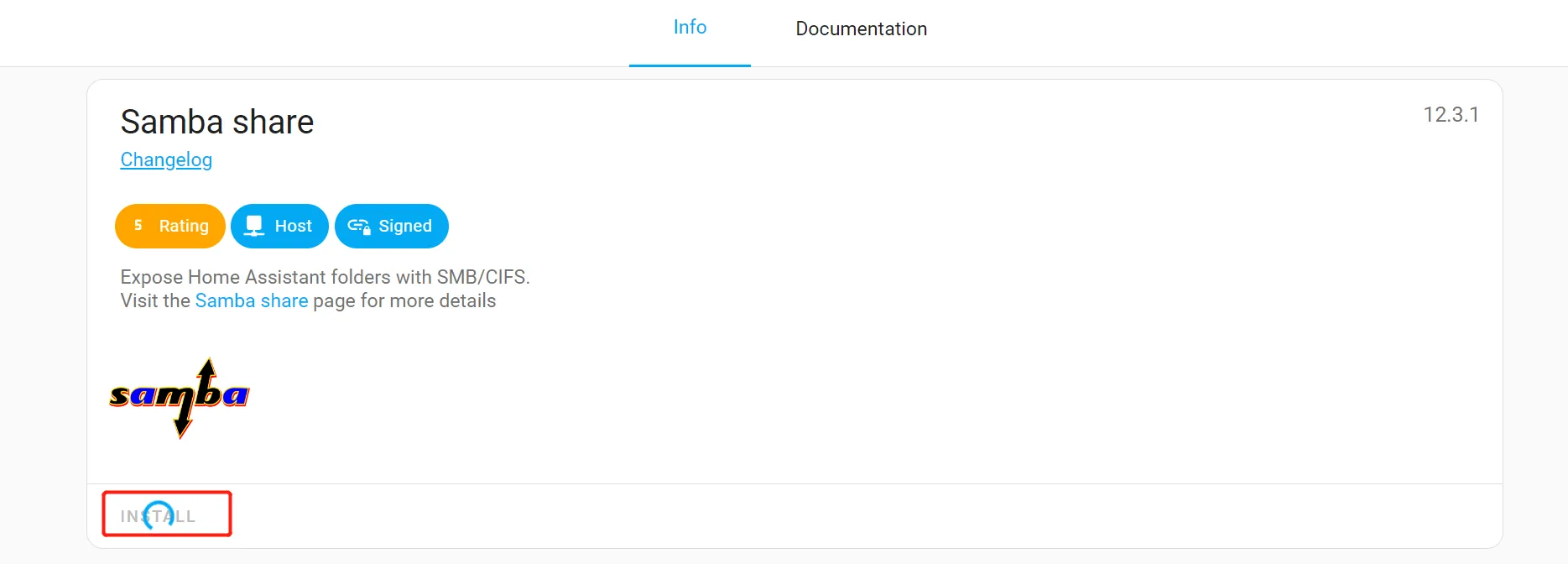
-
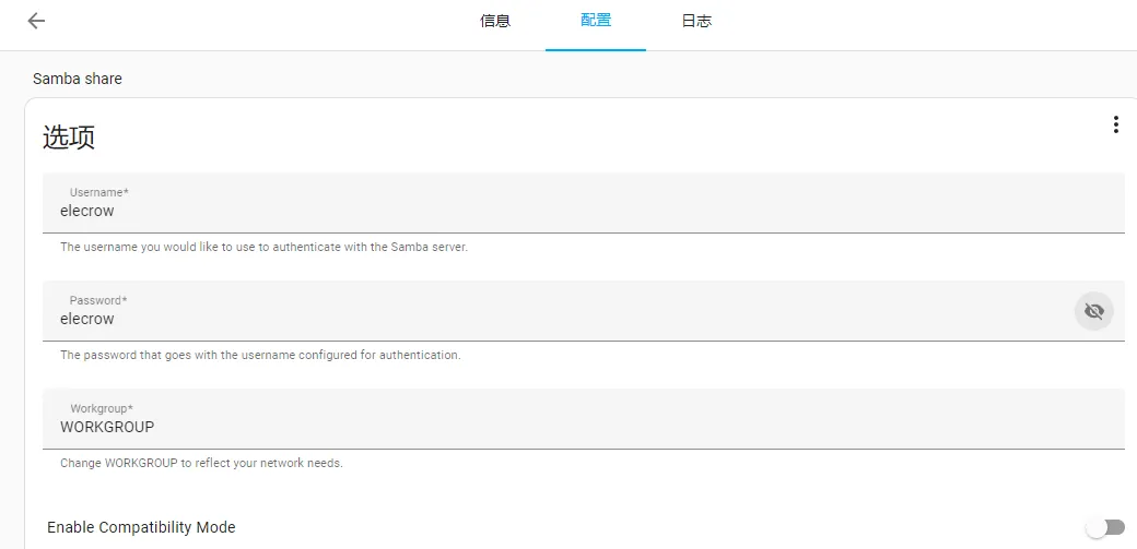
Enter the Samba share Configuration and enter the Username and Password
Tutorial on Arduino IDE
Get Started with Arduino IDE
Please click the card below to learn how to install Arduino IDE, and install RP2040 board in the Arduino IDE.

Upload the Code to PICO W5 Board
Please click  to download the PICO W5 Arduino Code.
-
Install "DHT20" library.
Copy the DHT20 in the libraries folder to the Sketchbook location.
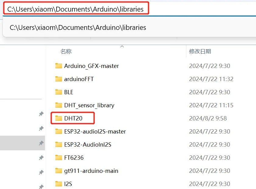
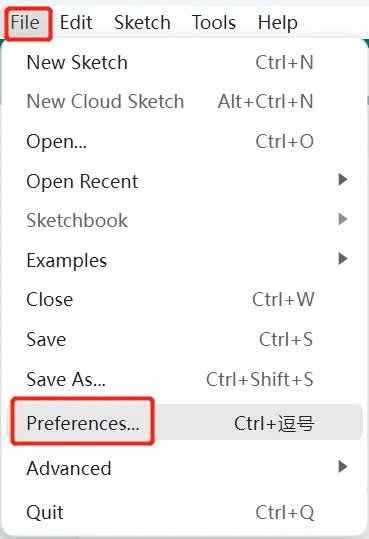
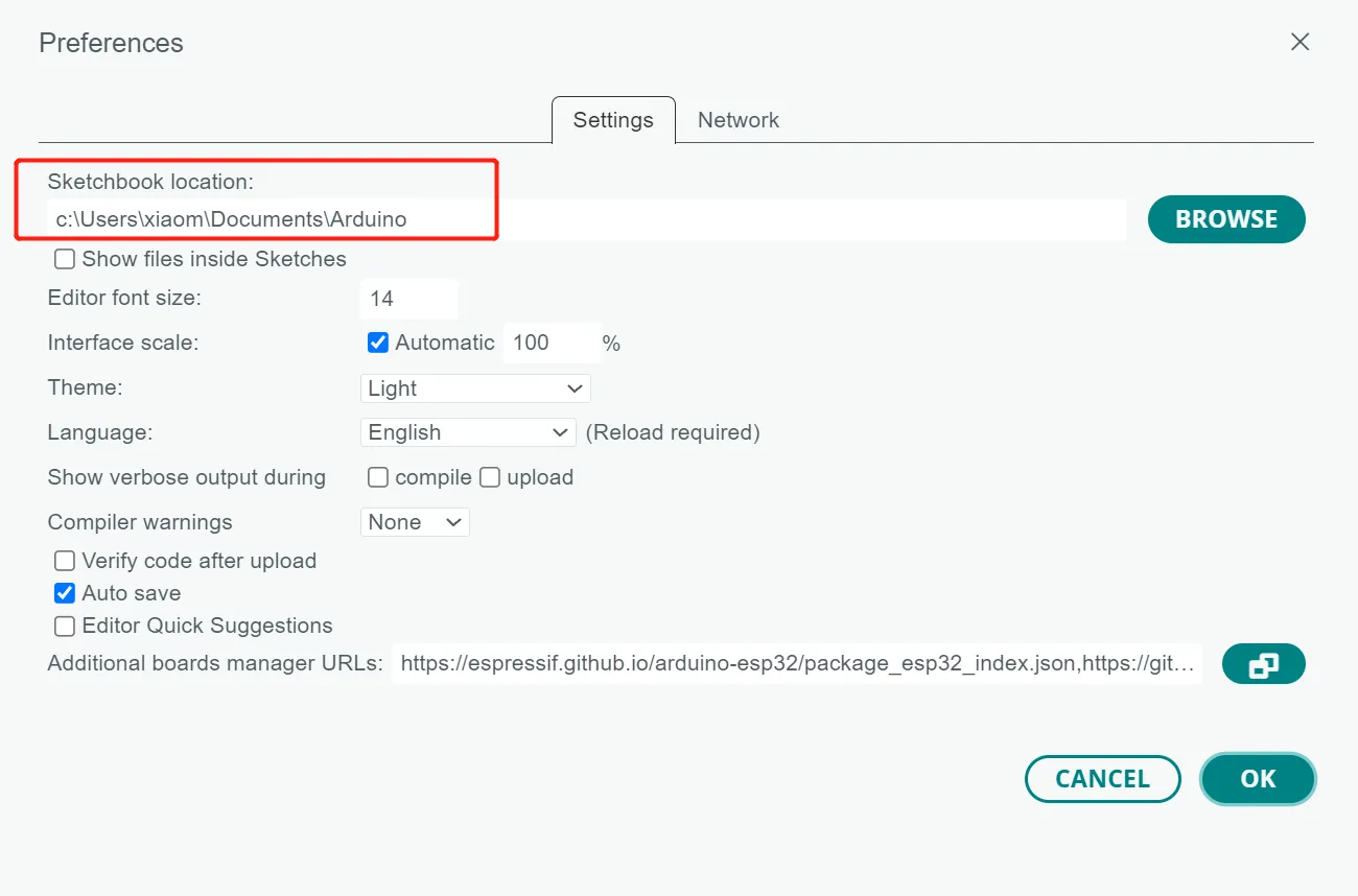
To find the Sketchbook location, please open the Arduino IDE, click "File"->"Preferences"->"Sketchbook Location".
-
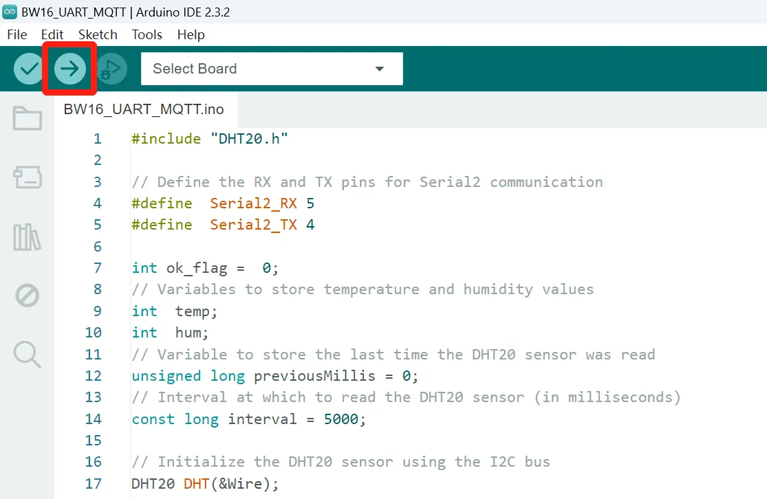
Enter the "HA_MQTT_Demo" folder and open BW16_UART_MQTT.ino
-
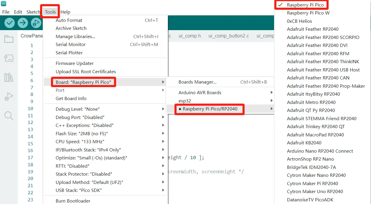
Click "Tool" -> "Board", and select the "Raspberry Pi Pico"
-
Connect the PICO W5 to the computer, and click "Tool"->"Port" to select the corresponding port number.
-
Click the "Upload" icon to upload the code. After the program is successfully downloaded, it will be prompted that the download is successful.
Connect with Home Assistant
-
Open "File Explorer" and type in
\\192.168.50.233to enter "config" folder. Open configuration.yaml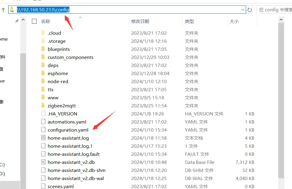
-
Add the following code in configuration.yaml to add the sensors.
mqtt: sensor: - unique_id: Temperature name: Temperature state_topic: PICOTP suggested_display_precision: 1 unit_of_measurement: °C value_template: '{{value_json.t}}' - unique_id: Humidity name: Humidity state_topic: PICORH suggested_display_precision: 1 unit_of_measurement: °C value_template: '{{value_json.h}}'- Please note the format indentation.
- The above is about enabling sensors in the yaml file configuration. For more information, please refer to the link: https://www.home-assistant.io/integrations/light.mqtt/.
- Note: After configuring the yaml file, you need to restart Homeassistant to update the configuration. It is recommended to use the default qos 0 in the configuration.
-
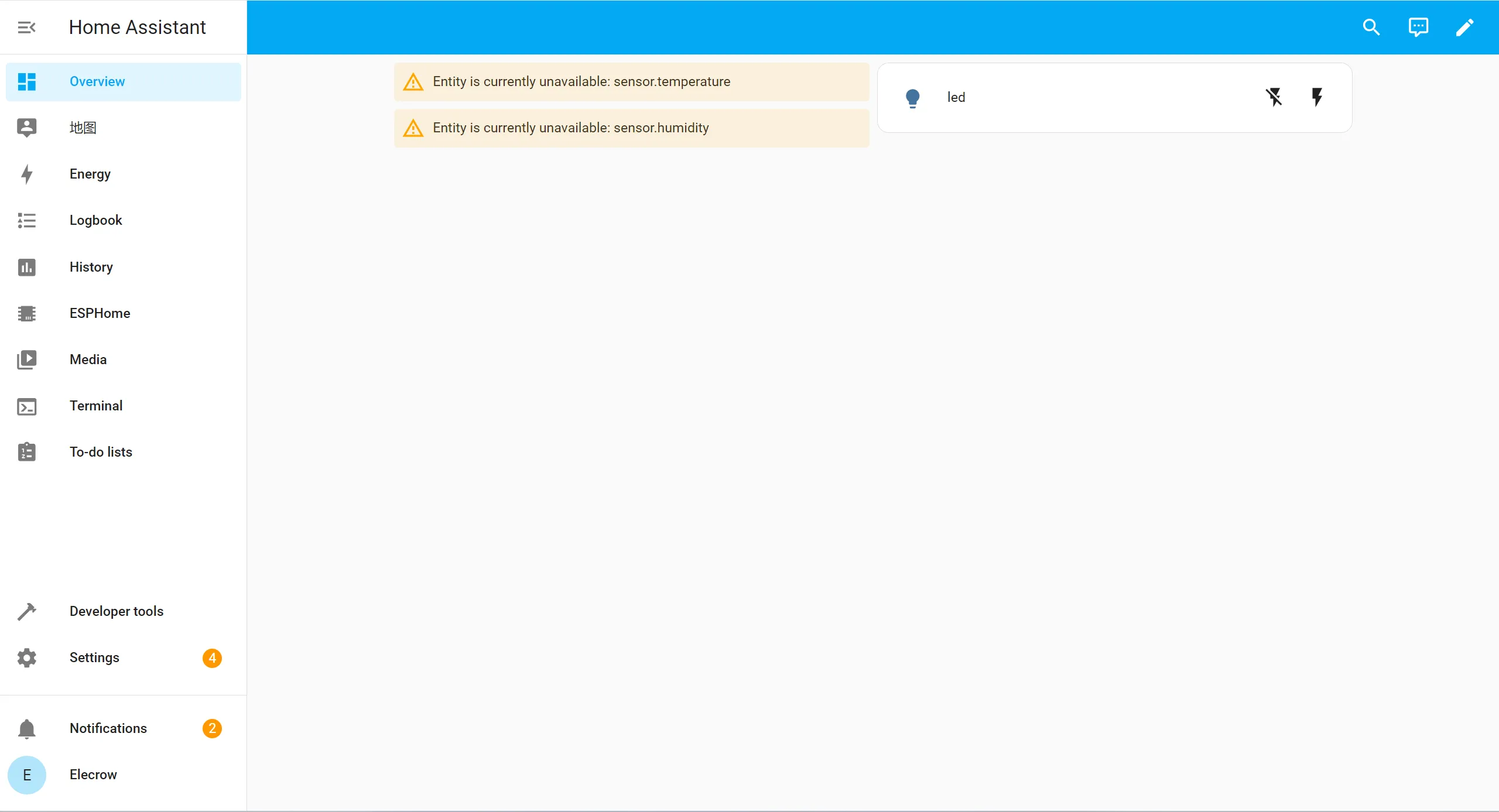
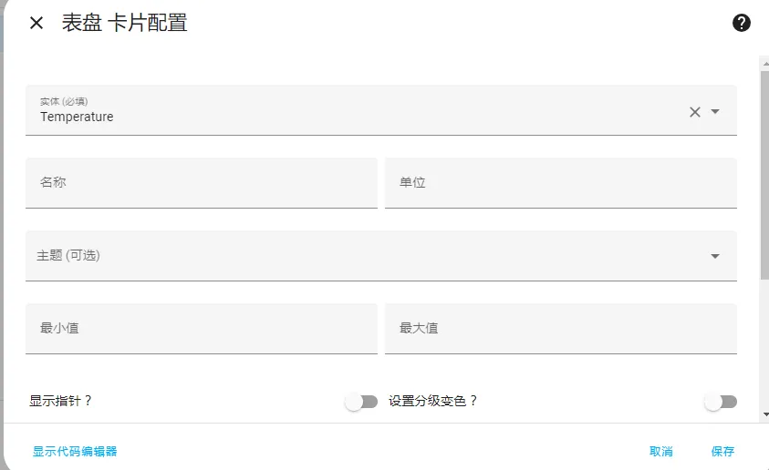
After saving the above code, go to the homepage -> Overview -> Edit Dashboard -> Add Card -> Select the entity just written in configuration.yaml in the card, the save.
-
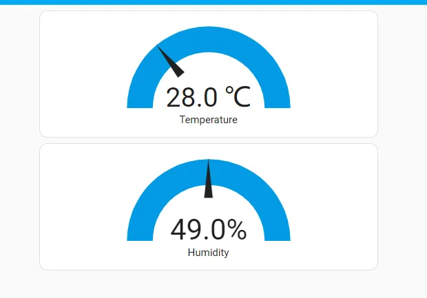
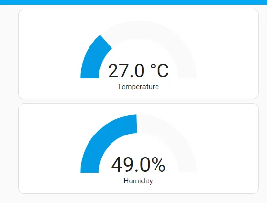
Get the temperature and humidity of the environment in real time and display it on the server
Tutorial on Thonny IDE
Download Thonny IDE
-
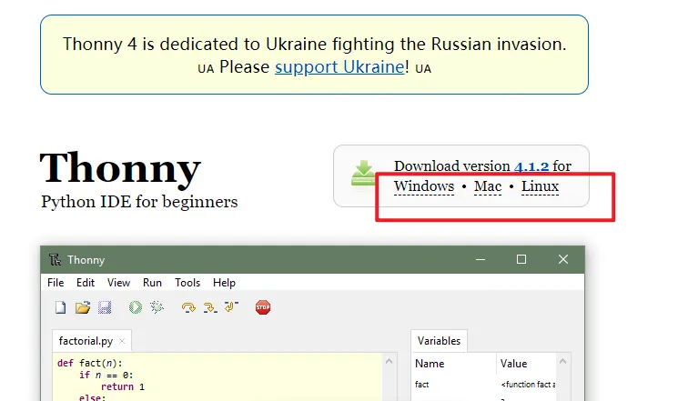
Go to the website https://thonny.org/ and download the corresponding software version (here we take the Windows version as an example)
-
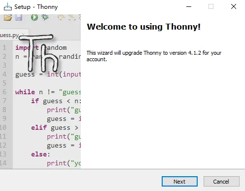
Double-click the downloaded exe file to install the software.
Upload Firmware
Method A
-
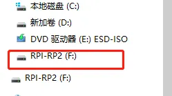
Connect the PICO W5 to the computer. And press BOOT button and REST button at the same time. There will be a U disk
-
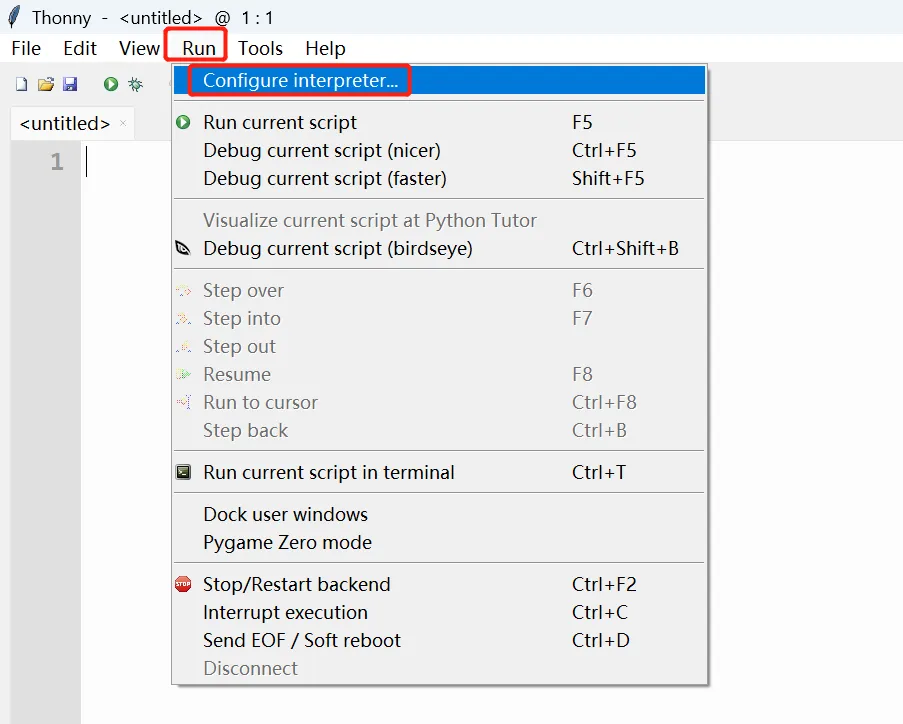
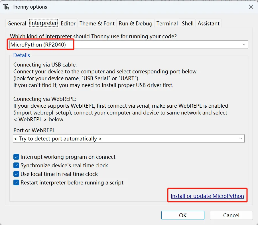
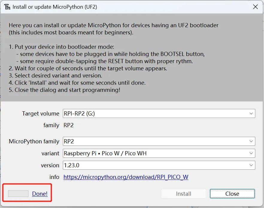
Open Thonny IDE and click "Run"->"Configure interpreter". Select "MicroPython(RP2040)" as the interpreter. Then click "Install and update MicroPython"
-
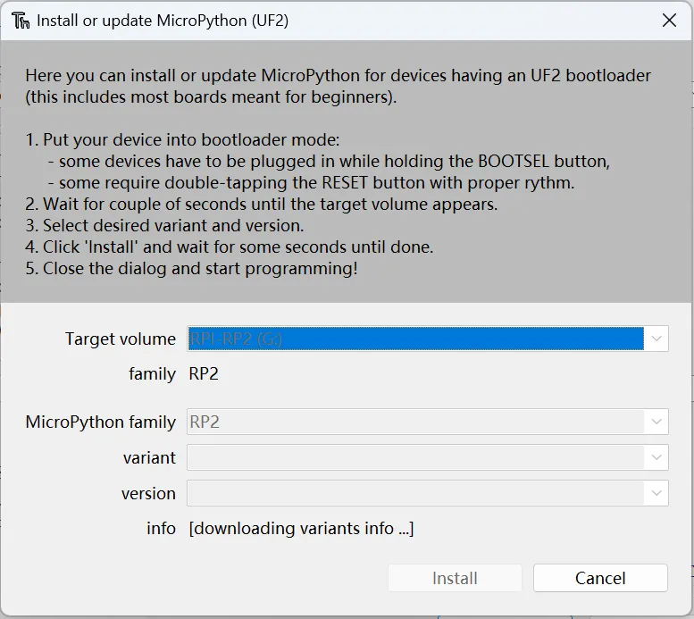
Waiting for the loading the downloading variants info...
After loading is complete, it will show:
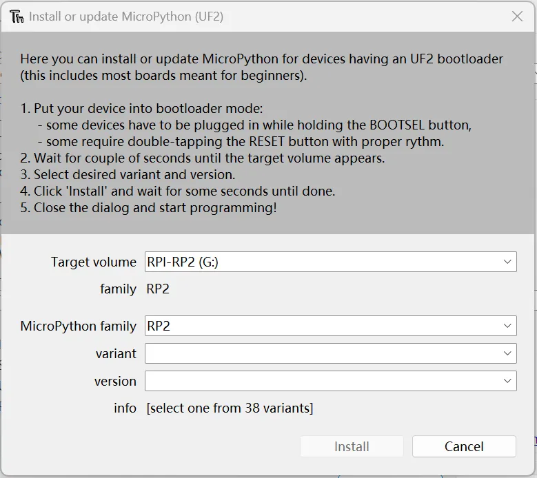
Select the variant to and install the firmware.
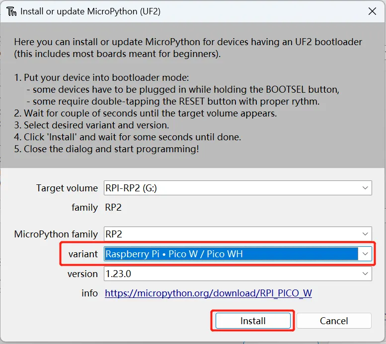
Installation is done!
Method B
-
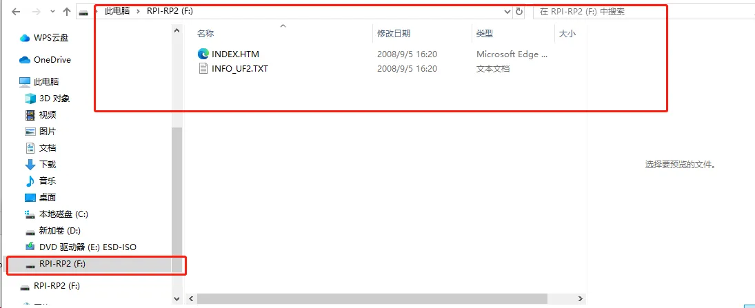
Connect the PICO W5 to the computer. And press BOOT button and REST button at the same time. There will be a U disk
-
Drag the firmware to the U disk

Please click to download the RPI_Pico_W5_2040_Firmware.
Please click to download the RPI_Pico_W5_2350_Firmware.
Add Library
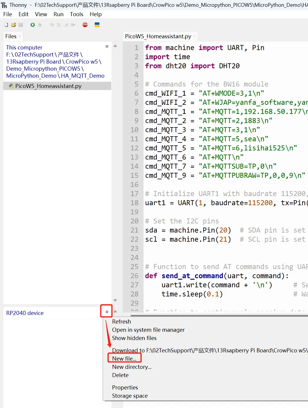
This tutorial requires the use of the DHT20 module, so you need to install the dht20 library.
-
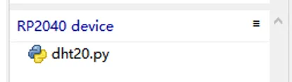
Click the menu icon in the upper right corner of RP2040 device. Select "New file..."
-
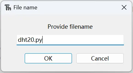
Name the file, note to add the file type suffix(.py)
-
Then copy the following to the editor.
# https://github.com/flrrth/pico-dht20 from machine import I2C from utime import sleep_ms class DHT20: """Class for the DHT20 Temperature and Humidity Sensor. The datasheet can be found at http://www.aosong.com/userfiles/files/media/Data%20Sheet%20DHT20%20%20A1.pdf """ def __init__(self, address: int, i2c: I2C): self._address = address self._i2c = i2c sleep_ms(100) # Added Columns self._i2c.writeto(0x38, bytearray(b'\x71')) sleep_ms(200) if not self.is_ready: self._initialize() sleep_ms(100) if not self.is_ready: raise RuntimeError("Could not initialize the DHT20.") @property def is_ready(self) -> bool: """Check if the DHT20 is ready.""" self._i2c.writeto(self._address, bytearray(b'\x71')) return self._i2c.readfrom(self._address, 1)[0] == 0x18 def _initialize(self): buffer = bytearray(b'\x00\x00') self._i2c.writeto_mem(self._address, 0x1B, buffer) self._i2c.writeto_mem(self._address, 0x1C, buffer) self._i2c.writeto_mem(self._address, 0x1E, buffer) def _trigger_measurements(self): self._i2c.writeto_mem(self._address, 0xAC, bytearray(b'\x33\x00')) def _read_measurements(self): buffer = self._i2c.readfrom(self._address, 7) return buffer, buffer[0] & 0x80 == 0 def _crc_check(self, input_bitstring: str, check_value: str) -> bool: """Calculate the CRC check of a string of bits using a fixed polynomial. See https://en.wikipedia.org/wiki/Cyclic_redundancy_check https://xcore.github.io/doc_tips_and_tricks/crc.html#the-initial-value Keyword arguments: input_bitstring -- the data to verify check_value -- the CRC received with the data """ polynomial_bitstring = "100110001" len_input = len(input_bitstring) initial_padding = check_value input_padded_array = list(input_bitstring + initial_padding) while '1' in input_padded_array[:len_input]: cur_shift = input_padded_array.index('1') for i in range(len(polynomial_bitstring)): input_padded_array[cur_shift + i] = \ str(int(polynomial_bitstring[i] != input_padded_array[cur_shift + i])) return '1' not in ''.join(input_padded_array)[len_input:] @property def measurements(self) -> dict: """Get the temperature (°C) and relative humidity (%RH). Returns a dictionary with the most recent measurements. 't': temperature (°C), 't_adc': the 'raw' temperature as produced by the ADC, 'rh': relative humidity (%RH), 'rh_adc': the 'raw' relative humidity as produced by the ADC, 'crc_ok': indicates if the data was received correctly """ self._trigger_measurements() sleep_ms(50) data = self._read_measurements() retry = 3 while not data[1]: if not retry: raise RuntimeError("Could not read measurements from the DHT20.") sleep_ms(10) data = self._read_measurements() retry -= 1 buffer = data[0] s_rh = buffer[1] << 12 | buffer[2] << 4 | buffer[3] >> 4 s_t = (buffer[3] << 16 | buffer[4] << 8 | buffer[5]) & 0xfffff rh = (s_rh / 2 ** 20) * 100 t = ((s_t / 2 ** 20) * 200) - 50 crc_ok = self._crc_check( f"{buffer[0] ^ 0xFF:08b}{buffer[1]:08b}{buffer[2]:08b}{buffer[3]:08b}{buffer[4]:08b}{buffer[5]:08b}", f"{buffer[6]:08b}") return { 't': t, 't_adc': s_t, 'rh': rh, 'rh_adc': s_rh, 'crc_ok': crc_ok } -
Click run, then the dht20.py will be added to RP2040 device
Connect with Home Assistant
-
Open "File Explorer" and type in
\\192.168.50.233to enter "config" folder. Open configuration.yaml -
Add the following code in configuration.yaml to add the sensors.
mqtt: sensor: - unique_id: Temperature name: Temperature state_topic: TP suggested_display_precision: 1 unit_of_measurement: °C value_template: '{{ value_json.t }}' - unique_id: humidity name: humidity state_topic: TP suggested_display_precision: 1 unit_of_measurement: °C value_template: '{{ value_json.h }}'- Please note the format indentation.
- The above is about enabling sensors in the yaml file configuration. For more information, please refer to the link: https://www.home-assistant.io/integrations/light.mqtt/.
- Note: After configuring the yaml file, you need to restart Homeassistant to update the configuration. It is recommended to use the default qos 0 in the configuration.
-
After saving the above code, go to the homepage -> Overview -> Edit Dashboard -> Add Card -> Select the entity just written in configuration.yaml in the card, the save.
-
Connect the sensor the PICO W5 board. Then open the "PicoW5_Homeassistant.py" on Thonny IDE and run.
Please click
to download the PICO W5 MicroPython Code. -
Get the temperature and humidity of the environment in real time and display it on the server
GPIO Example Demo - Arduino
Examples 1 LED Blinking
-
Plug the LED module to GPIO-16 Port.
Sensor PIN LED GP16 -
Upload the Blink.ino to CrowPico W5.
#define LED 16 // the setup function runs once when you press reset or power the board void setup() { // initialize digital pin LED as an output. pinMode(LED, OUTPUT); } // the loop function runs over and over again forever void loop() { digitalWrite(LED, HIGH); // turn the LED on (HIGH is the voltage level) delay(1000); // wait for a second digitalWrite(LED, LOW); // turn the LED off by making the voltage LOW delay(1000); // wait for a second } -
After the code is uploaded successfully, the LED will turn on and off repeatedly
Examples 2 Control the Breathing Light with PWM
-
Plug the LED module to GPIO-17 Port.
Sensor PIN LED GP17 -
Upload the PWM.ino to CrowPico W5.
#define PWM_PIN 17 //set pwn pin void setup () { // set pwm pin as outputs: pinMode(PWM_PIN, OUTPUT); } void loop() { // fade the LED on thisPin from off to brightest: for (int brightness = 0; brightness <= 255; brightness++) { analogWrite(PWM_PIN, brightness); delay(8); } // fade the LED on thisPin from brightest to off: for (int brightness = 255; brightness >= 0; brightness--) { analogWrite(PWM_PIN, brightness); delay(8); } // pause between LEDs: delay(800); } -
After the code is successfully uploaded, the brightness of the LED will gradually increase and then gradually decrease repeatedly.
Examples 3 Control the LED to Turn On or Off with a Button
-
Plug the LED module to GPIO-16 , and the button to GPIO-15.
Sensor PIN LED GP16 Button GP15 -
Upload the Button.ino to CrowPico W5.
const int buttonPin = 15; // the number of the pushbutton pin const int ledPin = 16; // the number of the LED pin // variables will change: int buttonState = 0; // variable for reading the pushbutton status void setup() { // initialize the LED pin as an output: pinMode(ledPin, OUTPUT); // initialize the pushbutton pin as an input: pinMode(buttonPin, INPUT); } void loop() { // read the state of the pushbutton value: buttonState = digitalRead(buttonPin); // check if the pushbutton is pressed. If it is, the buttonState is HIGH: if (buttonState == HIGH) { // turn LED on: digitalWrite(ledPin, HIGH); } else { // turn LED off: digitalWrite(ledPin, LOW); } } -
After the code is successfully uploaded, press the button to turn the LED on, press it again to turn the LED off.
Examples 4 Control the Light Intensity into an Analog Value
-
Plug the light sensor module to GPIO-27 Port.
Sensor PIN Light Sensor GP27 -
Upload the AnalogRead.ino to CrowPico W5.
-
After the code is successfully uploaded, the light intensity will be printed in the serial monitor.
Examples 5 Read Temperature and Humidity from DHT20 via I2C 0
-
Plug the DHT20 module to GPIO-20 and GPIO-21.
Sensor PIN SCL GP21 SDA GP20 -
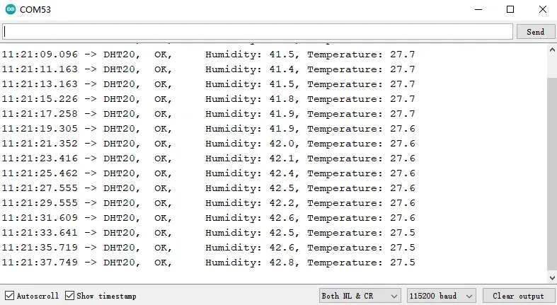
Upload the DHT20_test_rp2040_i2c0.ino to CrowPico W5.
#include "DHT20.h" DHT20 DHT(&Wire); // or use 2nd I2C interface &Wire void setup() { Serial.begin(115200); Serial.println(__FILE__); Serial.print("DHT20 LIBRARY VERSION: "); Serial.println(DHT20_LIB_VERSION); Serial.println(); Wire.setSDA(20); // select your pin numbers here Wire.setSCL(21); // select your pin numbers here Wire.begin(); delay(2000); Serial.println("Type,\tStatus,\tHumidity (%),\tTemperature (C)"); } void loop() { // READ DATA Serial.print("DHT20, \t"); int status = DHT.read(); switch (status) { case DHT20_OK: Serial.print("OK,\t"); break; case DHT20_ERROR_CHECKSUM: Serial.print("Checksum error,\t"); break; case DHT20_ERROR_CONNECT: Serial.print("Connect error,\t"); break; case DHT20_MISSING_BYTES: Serial.print("Missing bytes,\t"); break; case DHT20_ERROR_BYTES_ALL_ZERO: Serial.print("All bytes read zero"); break; case DHT20_ERROR_READ_TIMEOUT: Serial.print("Read time out"); break; case DHT20_ERROR_LASTREAD: Serial.print("Error read too fast"); break; default: Serial.print("Unknown error,\t"); break; } // DISPLAY DATA, sensor has only one decimal. Serial.print("Humidity: "); Serial.print(DHT.getHumidity(), 1); Serial.print(",\t"); Serial.print("Temperature: "); Serial.println(DHT.getTemperature(), 1); delay(2000); } // -- END OF FILE -- -
After the code is successfully uploaded, the humidity and temperature value will be printed in the serial monitor.
Examples 6 Control BW16 with AT Commands through UART1
-
The BW16 is soldered on board. The RX is connected with GP5, and the TX is connected with GP4.
-
Upload the BW16_UART.ino to CrowPico W5.
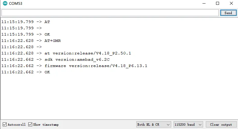
// Define the RX and TX pins for the second serial port #define Serial2_RX 5 // Set the RX pin #define Serial2_TX 4 // Set the TX pin // Initialize the second serial port void UART1_Init() { Serial2.setRX(Serial2_RX); // Set the RX pin for the second serial port Serial2.setTX(Serial2_TX); // Set the TX pin for the second serial port Serial2.begin(115200); // Start the second serial port at a baud rate of 115200 delay(1000); // Delay for 1 second to allow the serial port to initialize } // Setup function to initialize the main serial port and the second serial port void setup() { Serial.begin(115200); // Start the main serial port at a baud rate of 115200 UART1_Init(); // Initialize the second serial port } // Main loop function that prints "loop" and then delays void loop() { UART1_test(); } // Test function for the second serial port void UART1_test() { Serial2.println("AT"); delay(500); while (Serial2.available()) // Check if there is data available to read from the second serial port { Serial.write(Serial2.read()); // Write the data from the second serial port to the main serial port } Serial2.println("AT+GMR"); delay(500); while (Serial2.available()) // Check if there is data available to read from the second serial port { Serial.write(Serial2.read()); // Write the data from the second serial port to the main serial port } Serial.println(""); delay(500); } -
After the code is successfully uploaded, open the serial monitor.
Examples 7 Connect to the 5G band Wi-Fi
-
The BW16 is soldered on board. The RX is connected with GP5, and the TX is connected with GP4.
-
Upload the Connect_to_the_5G_band_Wi-Fi.ino to CrowPico W5.
Note: Serial1 is UART0, and Serial2 is UART1
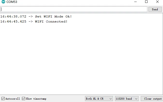
// Define the RX and TX pins for Serial2 communication #define Serial2_RX 5 #define Serial2_TX 4 // Flag to check the status of the WiFi connection int ok_flag = 0; // Define the command to set the WiFi mode to AP+STA #define SET_WIFI_MODE "AT+WMODE=3,1" // Define the command to set the WiFi SSID and password // Please replace "yanfa_software_5G" and "yanfa-123456" with your own SSID and password #define SET_WIFI_SSID_PASSWORD "AT+WJAP=\"yanfa_software_5G\",\"yanfa-123456\"" void setup() { // Initialize the serial communication at 115200 baud rate Serial.begin(115200); // Set the RX and TX pins for Serial2 communication Serial2.setRX(Serial2_RX); Serial2.setTX(Serial2_TX); // Start Serial2 communication at 115200 baud rate Serial2.begin(115200); // Delay for 5 seconds to allow the module to initialize delay(5000); // Call the UART2 test function UART2_test(); } void loop() { // Main code to run repeatedly // This loop is empty as the setup function does all the work } // Function to test UART2 communication and set WiFi configuration void UART2_test() { // Clear the serial buffer clear_serial(); // Reset the OK flag ok_flag = 0; // Send the command to set the WiFi mode Serial2.println(SET_WIFI_MODE); // Wait until the OK flag is set while (!ok_flag) { if (Serial2.find("OK")) { // Delay for 1 second delay(1000); // Set the OK flag to true ok_flag = true; // Print a message to indicate the WiFi mode has been set Serial.println("Set WIFI Mode Ok!"); } } // Clear the serial buffer again clear_serial(); // Reset the OK flag ok_flag = 0; // Send the command to set the WiFi SSID and password Serial2.println(SET_WIFI_SSID_PASSWORD); // Wait until the OK flag is set while (!ok_flag) { if (Serial2.find("OK")) { // Delay for 1 second delay(1000); // Set the OK flag to true ok_flag = true; // Print a message to indicate the WiFi is connected Serial.println("WIFI Connected!"); } } } // Function to clear the serial buffers for Serial and Serial2 void clear_serial() { // Clear Serial2 buffer while (Serial2.read() >= 0); // Clear Serial buffer while (Serial.read() >= 0); } -
After the code is successfully uploaded, open the serial monitor.
GPIO Example Demo - MicroPython
Examples 1 LED Blinking
-
Run the Blink.py
from machine import Pin from utime import sleep import utime # Connect the onboard LED to pin 25 # LED = Pin(id, mode, pull) # id: RP2040 pin number # mode: Input/output mode, with Pin.IN (input) and Pin.OUT (output) two options # pull: Pull-up/pull-down resistor configuration, with None (no pull resistor), Pin.PULL_UP (pull-up resistor), and Pin.PULL_DOWN (pull-down resistor) three options led = Pin(25, Pin.OUT) while True: # Turn on the LED led.value(1) utime.sleep_ms(1000) # Turn off the LED led.value(0) utime.sleep_ms(1000) -
The on-board LED will turn on and off repeatedly.
Examples 2 Control the Breathing Light with PWM
-
Plug the LED module to GPIO-16 Port.
Sensor PIN LED GP17 -
Run the PWM.py
from machine import Pin, PWM from time import sleep # Initialize a PWM object using Pin 16 pwm = PWM(Pin(16)) # Set the frequency of the PWM signal to 1000 Hz pwm.freq(1000) while True: # Increment the duty cycle from 0 to 65025 for duty in range(65025): pwm.duty_u16(duty) # Set the PWM duty cycle to the current value sleep(0.0001) # Delay for 0.0001 seconds to allow the change to take effect # Decrement the duty cycle from 65025 to 0 for duty in range(65025, 0, -1): pwm.duty_u16(duty) # Set the PWM duty cycle to the current value sleep(0.0001) # Delay for 0.0001 seconds to allow the change to take effect -
The brightness of the LED will gradually increase and then gradually decrease repeatedly.
Examples 3 Control the LED to Turn On or Off with a Button
-
Plug the LED module to GPIO-16 , and the button to GPIO-15.
Sensor PIN LED GP16 Button GP15 -
Run the Button.py.
from machine import Pin import time # Initialize the LED pin as an output pin on GPIO 16 led = Pin(16, Pin.OUT) # Initialize the button pin as an input pin on GPIO 15 with a pull-down resistor button = Pin(15, Pin.IN, Pin.PULL_DOWN) while True: # Check the button's value if button.value(): # If the button is pressed (value is high), toggle the LED state led.toggle() # Pause the program for 0.5 seconds to debounce the button time.sleep(0.5) -
Press the button to turn the LED on, press it again to turn the LED off.
Examples 4 Control the Light Intensity into an Analog Value
-
Plug the light sensor module to GPIO-27 Port.
Sensor PIN Light Sensor GP27 -
Run the AnalogRead.py.
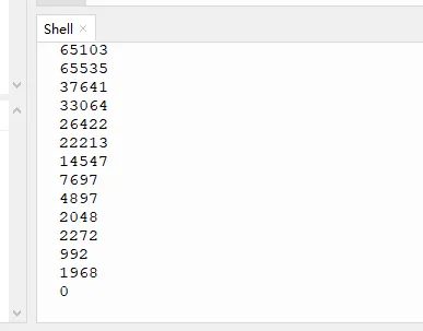
from machine import ADC, Pin import time # Initialize an ADC object using Pin 27 for analog input adc = ADC(Pin(27)) while True: # Read the analog value from the ADC and print it as a 16-bit unsigned integer print(adc.read_u16()) # Delay for 1 second to avoid overwhelming the output with too many readings time.sleep(1) -
The light intensity will be printed in the shell.
Examples 5 Read Temperature and Humidity from DHT20 via I2C 0
-
Plug the DHT20 module to GPIO-20 and GPIO-21.
Sensor PIN SCL GP21 SDA GP20 -
Run the I2C_DHT20.py.
import machine import utime # Set the I2C pins # SDA pin is set to GPIO pin 20 sda = machine.Pin(20) # SCL pin is set to GPIO pin 21 scl = machine.Pin(21) # Create an I2C object, select bus 0, assign the SDA and SCL pins, and set the bus frequency to 400kHz i2c = machine.I2C(0, sda=sda, scl=scl, freq=400000) # Import the DHT20 library from dht20 import DHT20 # Initialize the DHT20 sensor with its I2C address and the I2C bus dht20 = DHT20(0x38, i2c) while True: # Perform a measurement with the DHT20 sensor measurements = dht20.measurements # Extract the temperature from the measurements and convert it to an integer temp = int(measurements['t']) # Extract the relative humidity from the measurements and convert it to an integer hum = int(measurements['rh']) # Print the temperature and humidity values print(f"Temperature: {temp} °C, humidity: {hum} %RH") # Pause for 2 seconds before the next measurement utime.sleep(2) -
The humidity and temperature value will be printed in the shell.
Examples 6 Control BW16 with AT Commands through UART1
-
The BW16 is soldered on board. The RX is connected with GP5, and the TX is connected with GP4.
-
Run the Uart_Test.py
from machine import UART, Pin import time # Initialize UART1 with baudrate 115200, transmit on Pin(4), receive on Pin(5) uart1 = UART(1, baudrate=115200, tx=Pin(4), rx=Pin(5)) # Function to send AT commands def send_at_command(uart, command): uart1.write(command + '\n') # Send the command followed by a newline character time.sleep(0.1) # Wait for a response # Function to read the response from the module def read_response(uart): return uart1.read(1024) # Read a certain number of bytes from the UART buffer # Main loop while True: send_at_command(uart1, 'AT') # Send a test AT command to check the module's response response = read_response(uart1) print('Module Response0:', response) time.sleep(2) # Wait for 2 seconds before sending the next command send_at_command(uart1, 'AT+GMR') # Send a command to get the module's firmware version response = read_response(uart1) print('Module Response1:', response) time.sleep(2) # Wait for 2 seconds before the next iteration of the loop -
After the code is successfully uploaded, the AT command will be printed in the shell.

Examples 7 Connect to the 5G band Wi-Fi
-
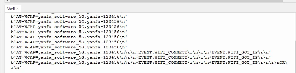
Send the command to connect to WiFi to the bw16 module through uart1 and receive the information returned by the bw16 module.
-
The BW16 is soldered on board. The RX is connected with GP5, and the TX is connected with GP4.
-
Run the Connect_to_the_5G_band_Wi-Fi.py
Note: Serial1 is UART0, and Serial2 is UART1
from machine import UART, Pin
import time

# Initialize UART1 with baudrate 115200, transmit on Pin(4), receive on Pin(5)
uart1 = UART(1, baudrate=115200, tx=Pin(4), rx=Pin(5))

# Function to send AT commands using UART1
def send_at_command(uart, command):
   uart1.write(command + '\n')     # Send the AT command followed by a newline for the module to process
   time.sleep(0.1)                 # Wait for the module to process the command and send a response

# Function to continuously receive data from UART1 until a newline character is detected
def Uart1_receive():
   data = b''          # Initialize an empty bytes object to store incoming data
   succeed = "OK"      # Expected success response from the module
   fail = "ERROR"      # Expected error response from the module

   while True:
      if uart1.any():              # Check if there is data available to read
            data += uart1.read()     # Read all available data into 'data'
      if data.endswith(b'\n'):     # Check if the data ends with a newline character
            if succeed in data:      # If the success response is in the data
               print(data)          # Print the received data
               break                # Exit the loop
            if fail in data:         # If the error response is in the data
               print(data)          # Print the received data
               break                # Exit the loop
            print(data)              # Print the data received so far
      time.sleep(0.5)              # Wait for 0.5 seconds before continuing

# Send an AT command to set the module's working mode
send_at_command(uart1, 'AT+WMODE=3,1')
Uart1_receive()
# Send an AT command to connect the module to a Wi-Fi network with the SSID "yanfa_software_5G" and password "yanfa-123456"
send_at_command(uart1, 'AT+WJAP=yanfa_software_5G,yanfa-123456')
Uart1_receive()