LR1262 LoRaWAN AT Command Description
Sum Up
It mainly introduces the AT commands for LR1262 module communication in the field of Internet of Things, including configuration, operation, data sending and receiving of LoRa modules.
1. Terms, definitions and acronyms
Terms and definitions
- LoRa
LoRa is one of the LPWAN communication technologies, which is an ultra-long-range wireless transmission solution based on spread spectrum technology adopted and promoted by Semtech.
Features: low power consumption, long distance, low cost.
- LoRaWAN
The LoRa Alliance is an open, non-profit organisation founded in March 2015, led by Semtech. The Alliance published a low-power WAN standard based on an open source MAC layer protocol: the LoRaWAN protocol standard.
Network topology: Star structure.
Network Composition: LoRa Module, Gateway, Server (including Network Server, Network Control and Application Server).
LoRaWAN classifies LoRa modules into A/B/C categories.
Acronyms
| Acronyms | Full name |
|---|---|
| MCU | Microcontroller Unit |
| MT | Mobile Terminal |
| TA | Terminal Agent |
| TE | Terminal Equipment |
2. Functional overview
The TE (Terminal Equipment) can control the functions of the MT (Mobile Terminal) and related network services by sending the AT commands described in this document. Terminal Agent (TA) performs the command and message adaptation function between the terminal equipment and the mobile equipment.
The physical realisation of the TE, TA and MT can be as follows:
- TE, TA and MT are three separate entities;
- TE is a separate entity and TA is integrated inside MT;
- MT is a separate entity and the TA is integrated inside the TE;
- TE, TA and MT are integrated into one entity.
In this document, TE is the MCU module of the IoT device and TA is the communication module and is integrated inside MT. Communication module means LoRa communication module.
The system structure of the terminal equipment (TE), terminal adapter (TA) and mobile terminal (MT) and the basic flow of establishing the association among them are shown in Fig.
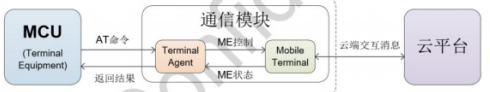
According to the picture, we can see that the MCU module and the communication module are integrated together in the IoT device, and the MCU communicates with the TA through AT commands to control the MT (ME refers to mobile equipment) and realise the interaction between the IoT device and the cloud.
The interaction with the cloud is carried out through LoRa. In this document, the standard AT commands are extended to support LoRa commands, etc., so as to realise the message interaction between the IoT device and the cloud.
AT Command Syntax
The AT command uses an ASCII-based command line with the following command format:
The request message format is: AT+
| domain | clarification |
|---|---|
| AT+ | command message prefix |
| CMD | command string |
| Op | Command Operator. It can be the following:"=": indicates a parameter setting."?" : Indicates the current value of the query parameter." ": indicates the execution of the command."=?" : Indicates the parameter of the query setting command. |
| para-1,para-2,……para-n | Indicates the value of the parameter to be set, or specifies the parameter to be queried |
| \R | Carriage return terminator, ASCII code 0x0D |
Response message format is <\r\n>[+CMD:][para-1,para-2,......para-n]<\r\n> or <\r\n>
| domain | clarification |
|---|---|
| \r\n | Line break, ASCII code 0x0A |
| +CMD | The corresponding command string |
| para-1,para-2,……para-n | The corresponding parameter string |
| STATUS | Command execution status. It can be the following:"OK": indicates that the command execution was successful."ERROR": indicates that the command execution failed."+CME ERROR: |
Clarification
(1) <>: Indicates what must be included.
(2) [ ]: indicates optional content.
(3) \r: carriage return terminator, ASCII code is 0x0D
(4) \n: Line feed character, ASCII code is 0x0A.
(5) For example, to query the connection mode of MQTT, send the command as:
- AT+IMQTTMODE?\r
(7) The reply message is:
-
\r\n+IMQTTMODE:1\r\n
-
\r\nOK\r\n
Note: \r\n is hidden in the following text for ease of reading
(1). Parameter configuration of serial port:
- baud rate 115200, data bit 8, stop bit 1, parity bit 0.
(2). The current commands support back display, temporarily do not support BackSpace, temporarily do not support back flip history commands.
Sample program description
1. Jumper connection
The LORAWAN_AT project uses a low-power serial port for reception, a power supply section, a reset button, an antenna and a USB connection.
2. Code location (to be added later)
3. Serial port settings
The serial port configuration information is as follows:
4.Example
The following is an example of the steps to configure the network entry using the AT command for node A:
(1) Node A Information
DevEui: 70B3D57ED005B7FF
AppEui: 0000000000000003

AppKey: A8D7E5959F7746D902BF52BA2F899E3E
Node Type: ClassA
Gateway Frequency Group Mask: 0001
(2) Setting Channel Mode
(3) Set the node entry frequency band
(4) Node triad information configuration
(5) Start networking

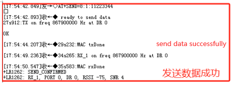
(6) Send data
 ]{ loading=lazy }
AT command commands
| Command | Parameter | Explanation |
|---|---|---|
| AT+RESET | None | //Reset command |
| AT+RFS | None | //Clear Flash Data |
| AT++SAVE | None | //Save to flash memory |
| AT+VL | [=verb_lvl], verb_lvl = [0:3] | //Set the level of detail for obtaining information |
| AT+LTIME | [=?] | //Get the local time in UTC format. |
Key, ID and EUL Management Commands
| Command | Parameter | Explanation |
|---|---|---|
| AT+AppEui | [=0102030405060708] (16 bit EUI) | //set/get application EUI |
| AT+NwkKey | [=2B7E151628AED2A6ABF7158809CF4F3C] | //Set/Get Network Root Key |
| AT+AppKey | [=2B7E151628AED2A6ABF7158809CF4F3C] | //Set/Get Application Root Key |
| AT+NwkSKey | [=2B7E151628AED2A6ABF7158809CF4F3C] | //Set/Get Application Session Key |
| AT+AppSKey | [=2B7E151628AED2A6ABF7158809CF4F3C] | //Set/Get Network Session Key |
| AT+DevAddr | [=01020A0B] | //Set/get device address |
| AT+DevEui | [=0123456789ABCDEF] | //Set/get the unique ID of the module |
| AT+NWKID | [=127] | //Setup Get Network ID |
LoRaWAN join and send data commands
| Command | Parameter | Explanation |
|---|---|---|
| AT+JOIN | =1,3 (Parameter 1 is the entry mode selection (OTAA, ABP), parameter 2 is the number of cyclic entries (valid only in OTAA mode range (1-8))) | //Join the network |
| AT+LINKC | // Send out MAC command request to the next uplink | |
| AT+SEND[=port_nb:confirmedmode:data]where confirmedmode = 0 or 1. | //Send data to the network |
LoRaWAN network management commands
| Command | Parameter | Explanation |
|---|---|---|
| AT+VER | [=class] where class = [A, B or C] | // Get the version of the LoRa WAN |
| AT+ADR | [=dutycycle] where dutycycle = 0 or 1 | //Set/Get Adaptive Data Rate Function |
| AT+BAND | [=5,0] (Parameter 1 is band selection selectable (5 or 8), Parameter 2 is channel selection 868 (3), 915 (8)) (For multiple channels, only the first parameter is needed) | //Set/Get band area |
| AT+DR | [=delay] where delay in ms (need to turn off AT+ADR=0 before setting, parameters 0-7) | //Set/Get Data Rate |
| AT+CLASS | [=delay] where delay in ms, AT+CLASS=A or B or C , need to JOIN successfully before setting | // Setting up the node ABC class |
| AT+DCS | [=delay] where delay in ms, AT+DCS=0 or 1 | //set/get connection delay on Rx window 1 |
| AT+JN1DL | [=delay] where delay in ms | //Set/Get connection delay on Rx window 2 |
| AT+JN2DL | [=datarate] where X = [0:7] | //set/get delay for Rx window 1 |
| AT+RX1DL | [=delay] where delay in ms | //set/get delay for Rx window 1 |
| AT+RX2DL | [=delay] where delay in ms | //Set/Get delay for Rx window 2 |
| AT+RX2DR | [=datarate] where X = [0:7] | //Set/Get data rate for Rx window 2 |
| AT+RX2FQ | [=freq] where freq in Hz, AT+RX2FQ=868100000 need to set AT+BAND=5 then follow up with lorawan protocol downstream to set it up | //Set/get the frequency of Rx window 2 |
| AT+TXP | [=txpow] where txpow = [0:7] | //Set/Get transmit power |
| AT+PGSLOT | [=periodicity]AT+PGSLOT=0 Parameters 0-7 | //Set/get unicast ping slot period. If the end device is already connected, resend PingSlotInfoReq |
Radio Test Command
| Command | Parameter | Explanation |
|---|---|---|
| AT+TTONE | None | // Set the RF tone test. |
| AT+TRSSI | None | // Set the RF RSSI tone test. |
| AT+TCONF | [=freq:pow:bw:sf:cr:lna:pa :mod:paylen:freqdev :lowdropt:BT]AT+TCONF=868000000:14:4:12:⅘:0:0:1:16:25000:2:3 | //Setup/Get Configuration LoRa RF Test. |
| AT+TTX | [=nb_packets_sent] | // Configure the number of messages sent by the PER RF Tx test. |
| AT+TRX | [=nb_packets_received] | // Configure the number of messages received by the PER RF Rx test case. |
| AT+CERTIF | [=mode] where mode = 0 (ABP) or mode = 1 (OTAA) | // Set the module in LoRaWAN authentication to connection mode. |
| AT+TTH | [= | //Activate RF Tx frequency hopping test from Fstart to Fstop (in Hz or MHz), Fdelta (in Hz) |
| AT+TOFF | None | //Stop RF test. |
| AT+BAT | AT+BAT=? | //Getting Battery Level |
Added command
| Command | Parameter | Explanation |
|---|---|---|
| AT+ChannelMode | [=0] (0 is single channel, 1 is multi-channel, default is multi-channel) | //Set/Get Channel Mode |
| AT+LowPower | [ =1 ] (0 is off low power, 1 is on low power, default is on low power) | //Setting the power consumption mode |