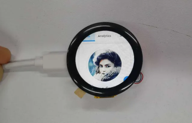
ESP32 1.28-inch Round Display Tutorial
Over All
This tutorial demonstrates programming methods on Arduino IDE and Thonny IDE.
-
This tutorial demonstrates how to connect the ESP32 1.28-inch Round Display to the Home Assistant server on the Arduino IDE, and control the vibration motor. In addition, there are examples to demonstrate how to design lvgl widgets, control GPIO, connect Blutooth and connect WiFi, etc.
-
Since the program is too large to run on Thonny IDE, the memory of ESP32-C3 is insufficient. This tutorial only provides methods for using interfaces, without using lvgl to display image on the display.
Home Assistant Server Configuration
Install Home Assistant OS
-
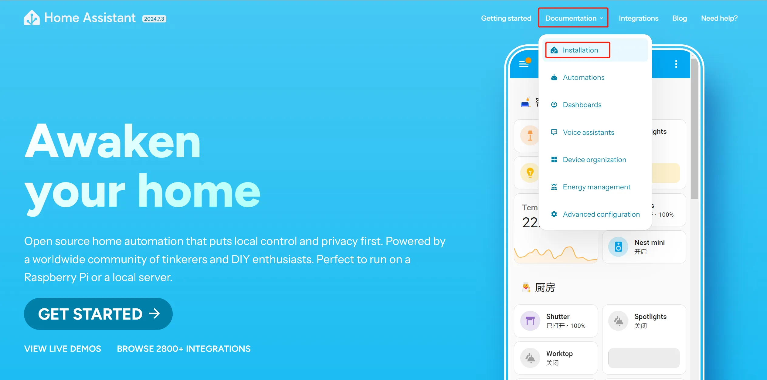
Go to https://www.home-assistant.io/, and click the "Installation" under "Documentation" on the homepage.
-
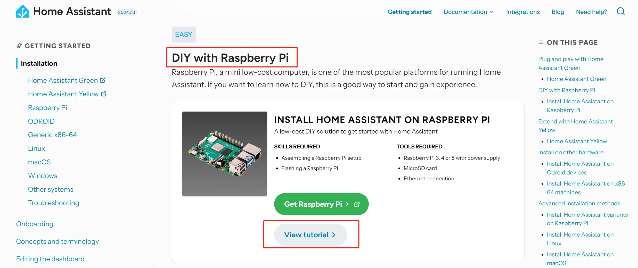
Scroll down to the "DIY with Raspberry Pi" section, and click "View tutorial".
-
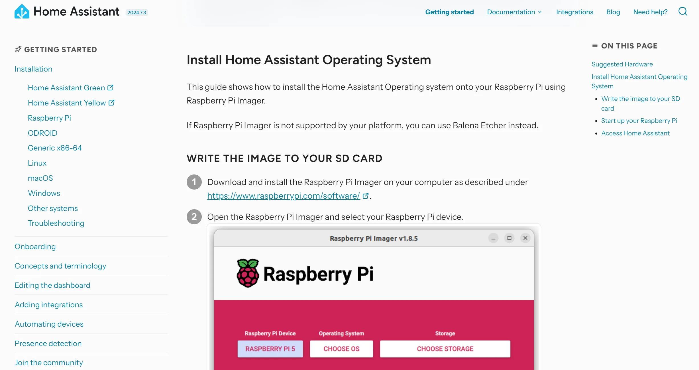
Follow the Home Assistant tutorial to install Operating System.
-
Eject the SD card after the Home Assistant OS is written.
-
Start up your Raspberry Pi.
- Insert the SD card into your Raspberry Pi.
- Plug in an Ethernet cable and make sure the Raspberry Pi is connected to the same network as your computer and is connected to the Internet.
- Connect the power supply to start up the device.
Register for Home Assistant
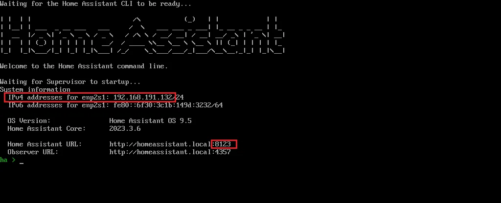
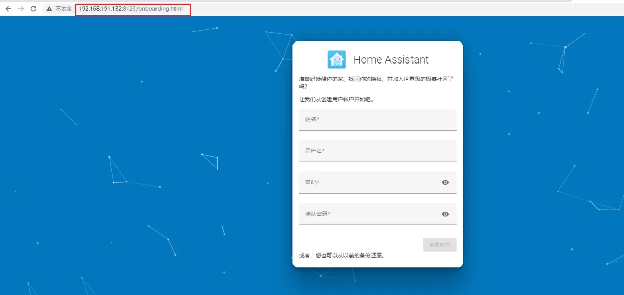
Within a few minutes after connecting the Raspberry Pi, you will be able to reach your new Home Assistant.
- 192.168.191.132: this is the IP address of my Raspberry Pi, it is assigned by the router.
-
8123: this is the port number, it is fixed.
-
In the browser of your desktop system, enter homeassistant.local:8123.
Note
If you are running an older Windows version or have a stricter network configuration, you might need to access Home Assistant at homeassistant:8123 or
http://X.X.X.X:8123(replace X.X.X.X with your Raspberry Pi’s IP address).The time it takes for this page to become available depends on your hardware. On a Raspberry Pi 4 or 5, this page should be available within a minute.
- If it does not show up after 5 minutes on a Pi 4 or 5, maybe the image was not written properly.
- Try to flash the SD card again, possibly even try a different SD card.
- If this did not help, view the console output on the Raspberry Pi.
- To do this, connect a monitor via HDMI.
-
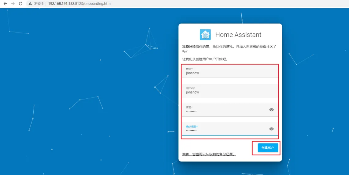
For the first visit, you need to create an account. Fill in the username and password, and create an account.
-
Region selection. You can manually locate or select automatic detection.
-
Next, click Next by default.
-
Then click Finish. It will prompt you to add a smart device. You can click Finish first and then set it up yourself.
-
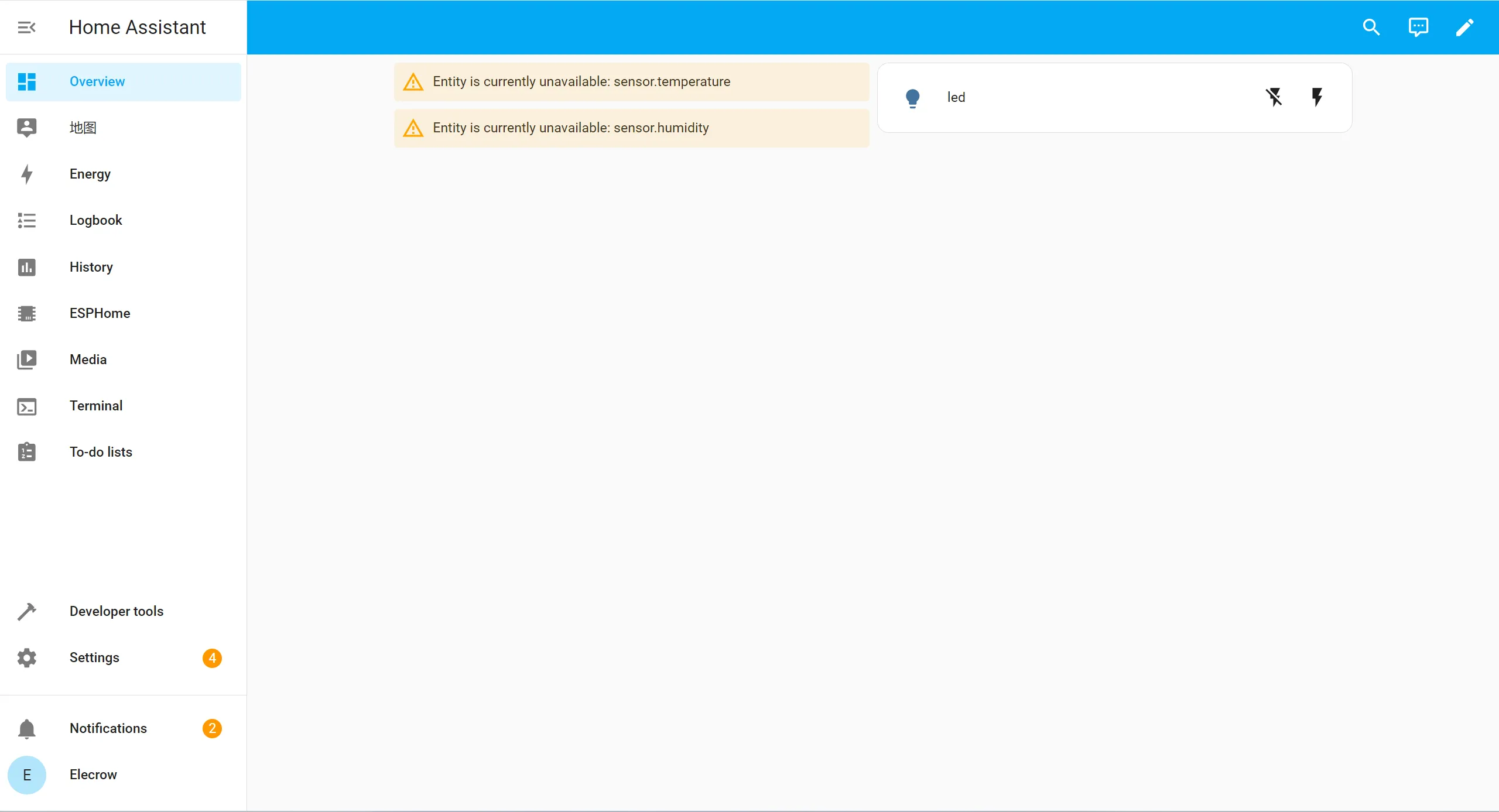
Then enter the control panel interface
Access Home Assistant and Set MQTT
Note: The Raspberry Pi and the computer need to be in the same LAN (same network).
-
In the browser of your desktop system, enter homeassistant.local:8123.
-
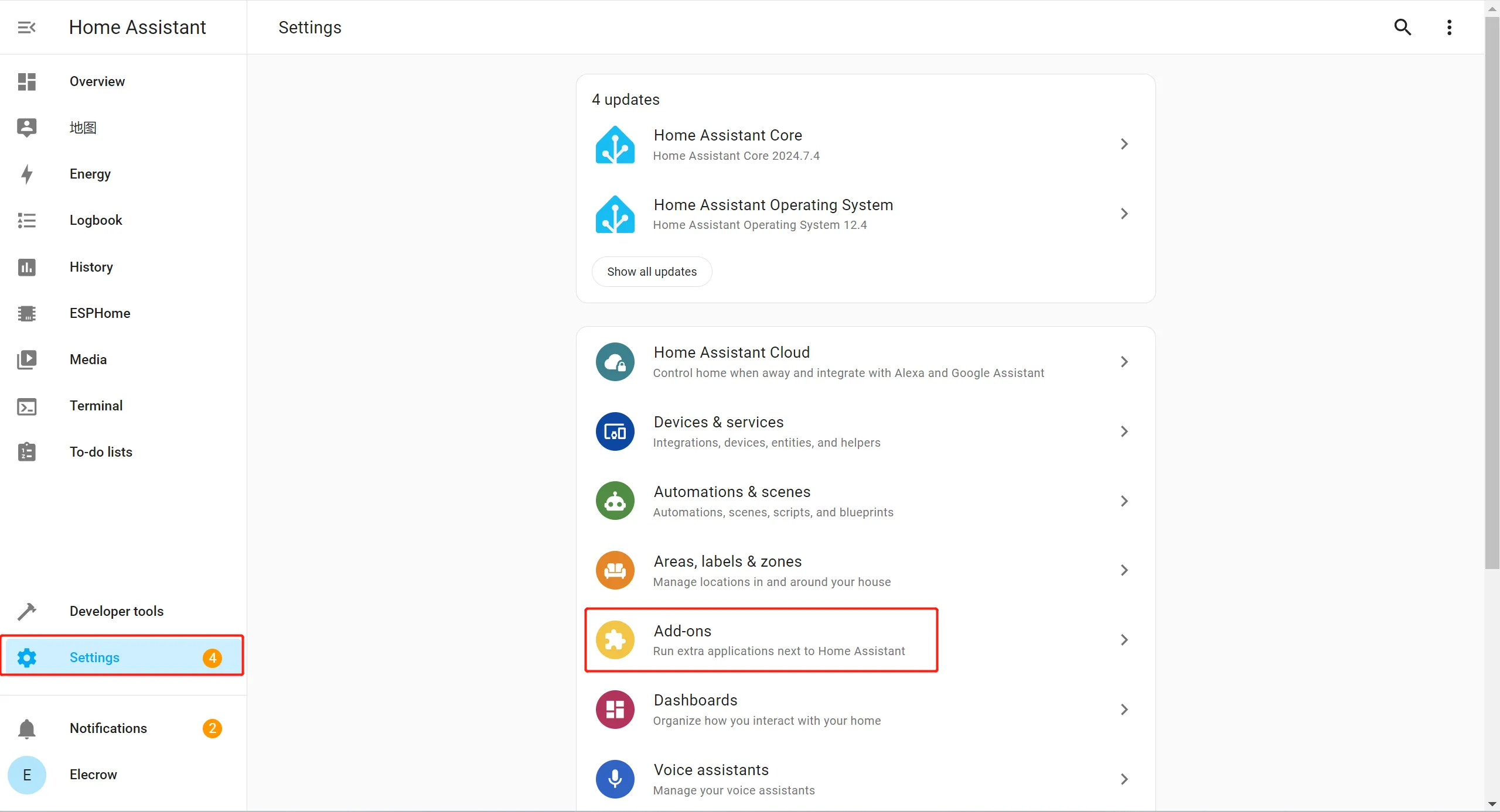
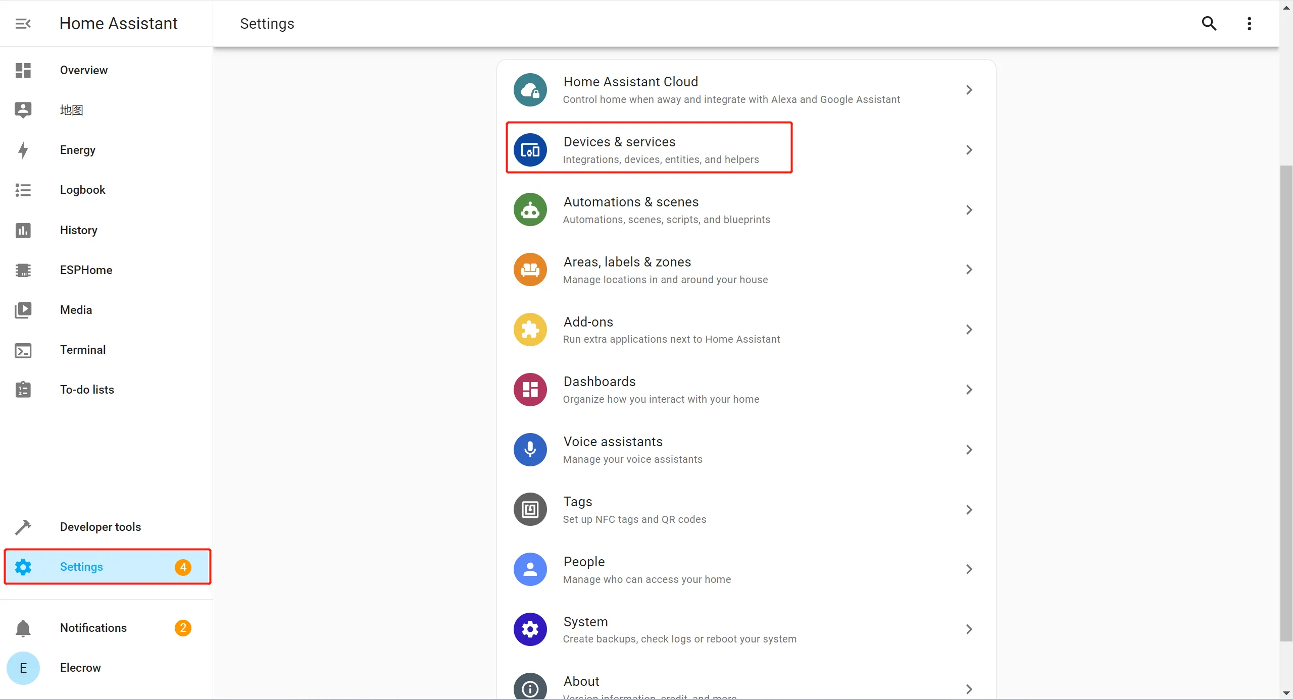
Click "Setting" -> "Add on"
-
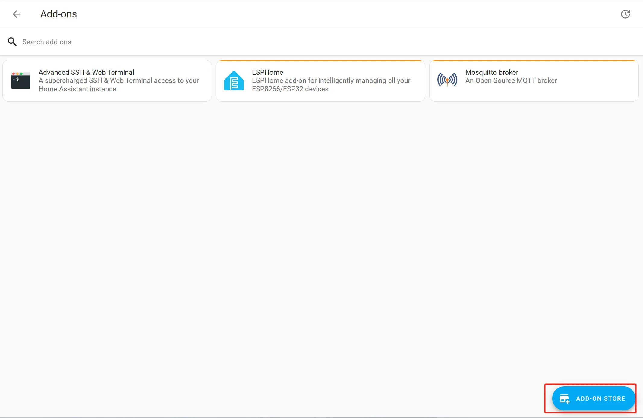
Click ADD-ON STORE
-
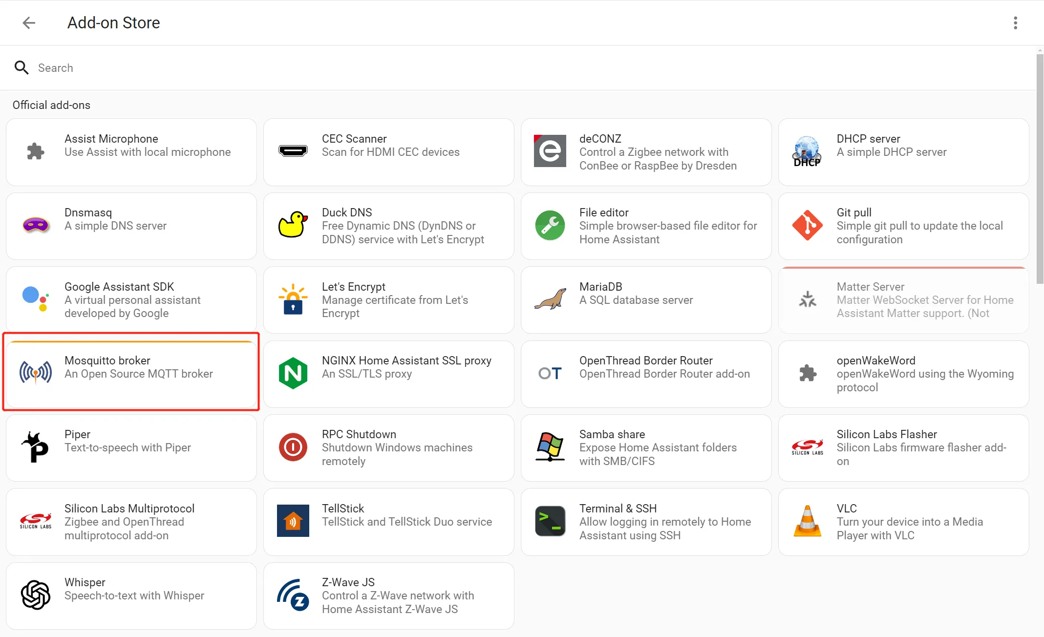
Select "Mosquitto broker" and install
-
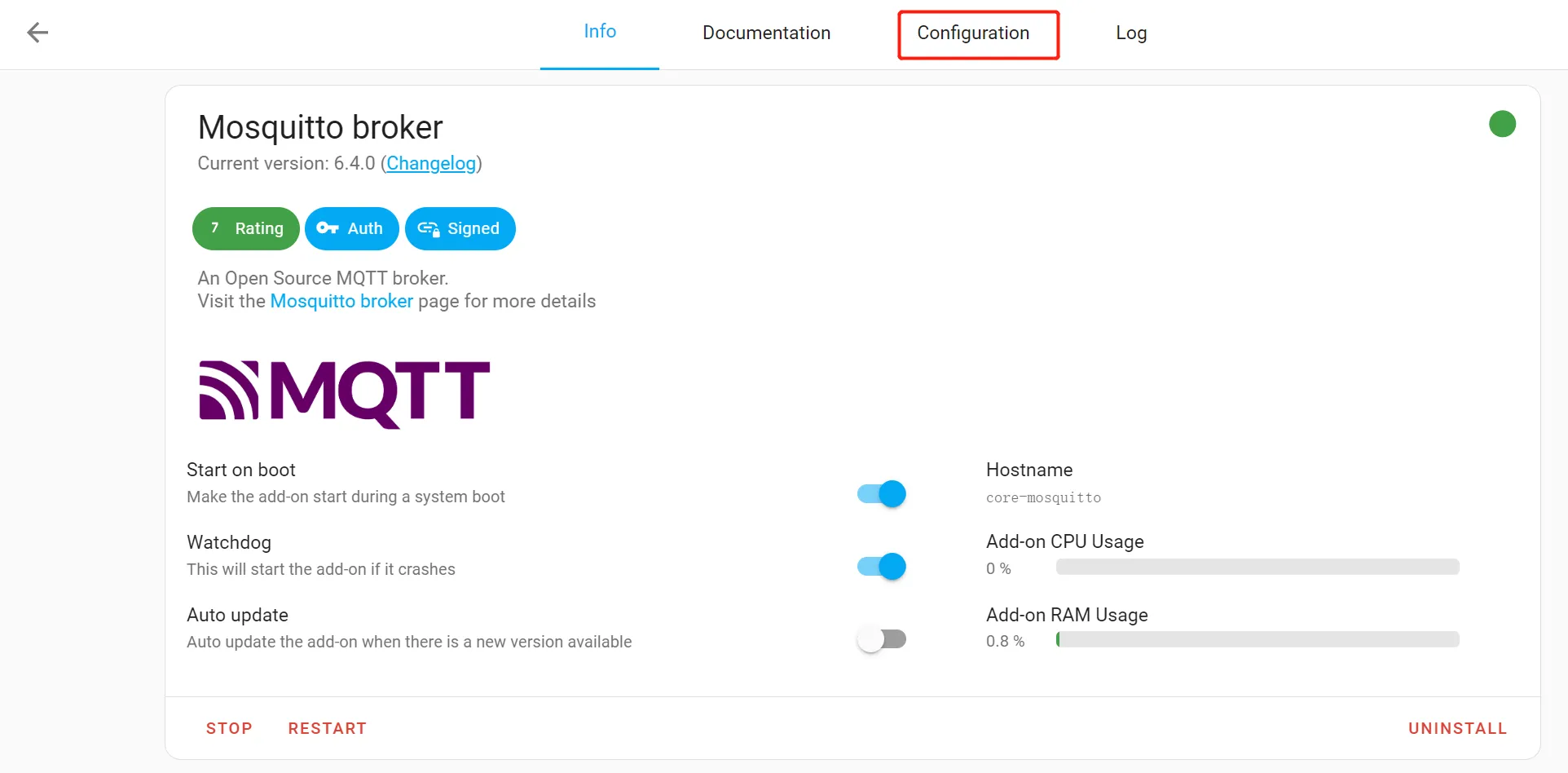
Enable Mosquitto broker
-
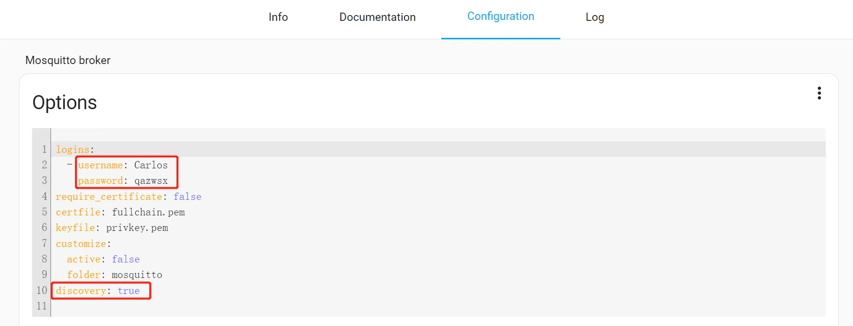
Then click "Configuration" -> "Options" -> "Logins", and set the username and password.
Click the three-dot icon, then click "Edit in YAML"
Modify the username and password, and set the discovery to "true".
-
Click "Setting"-> "Devices&Service"
-
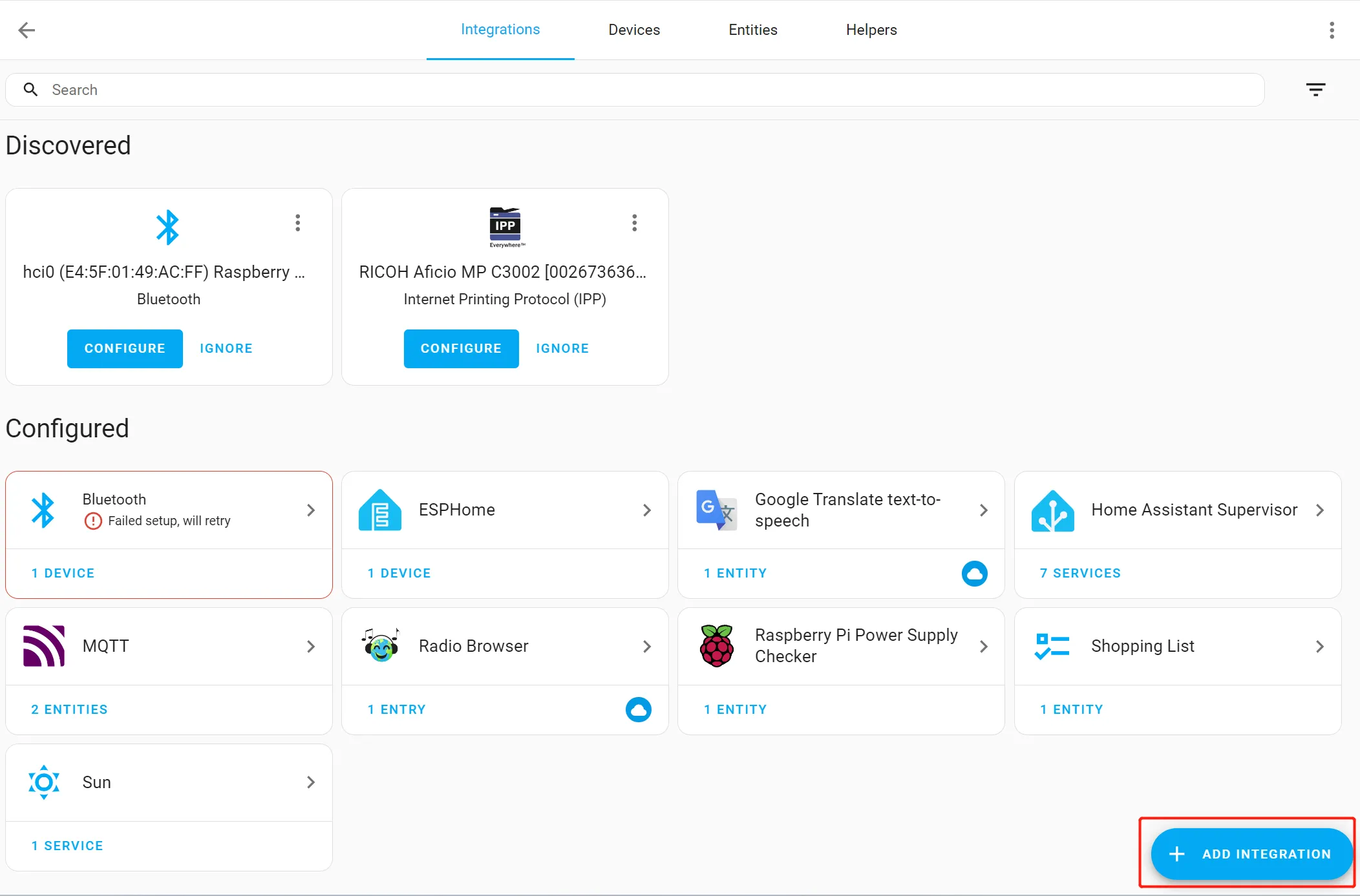
Click "ADD INTEGRATION"
-
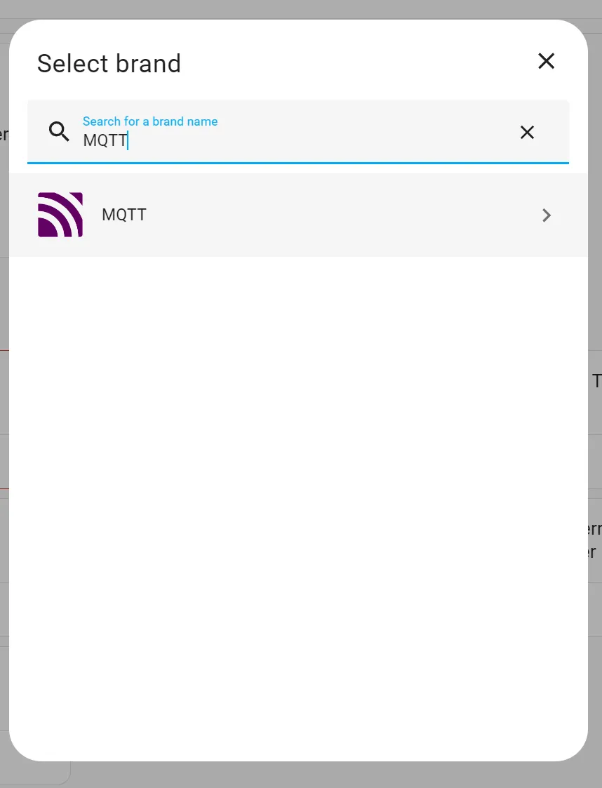
Search for "MQTT"
-
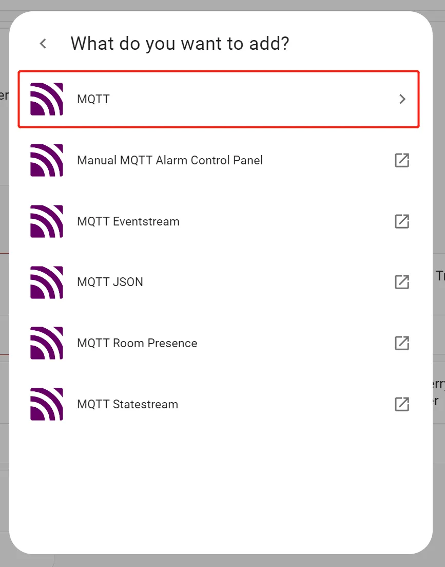
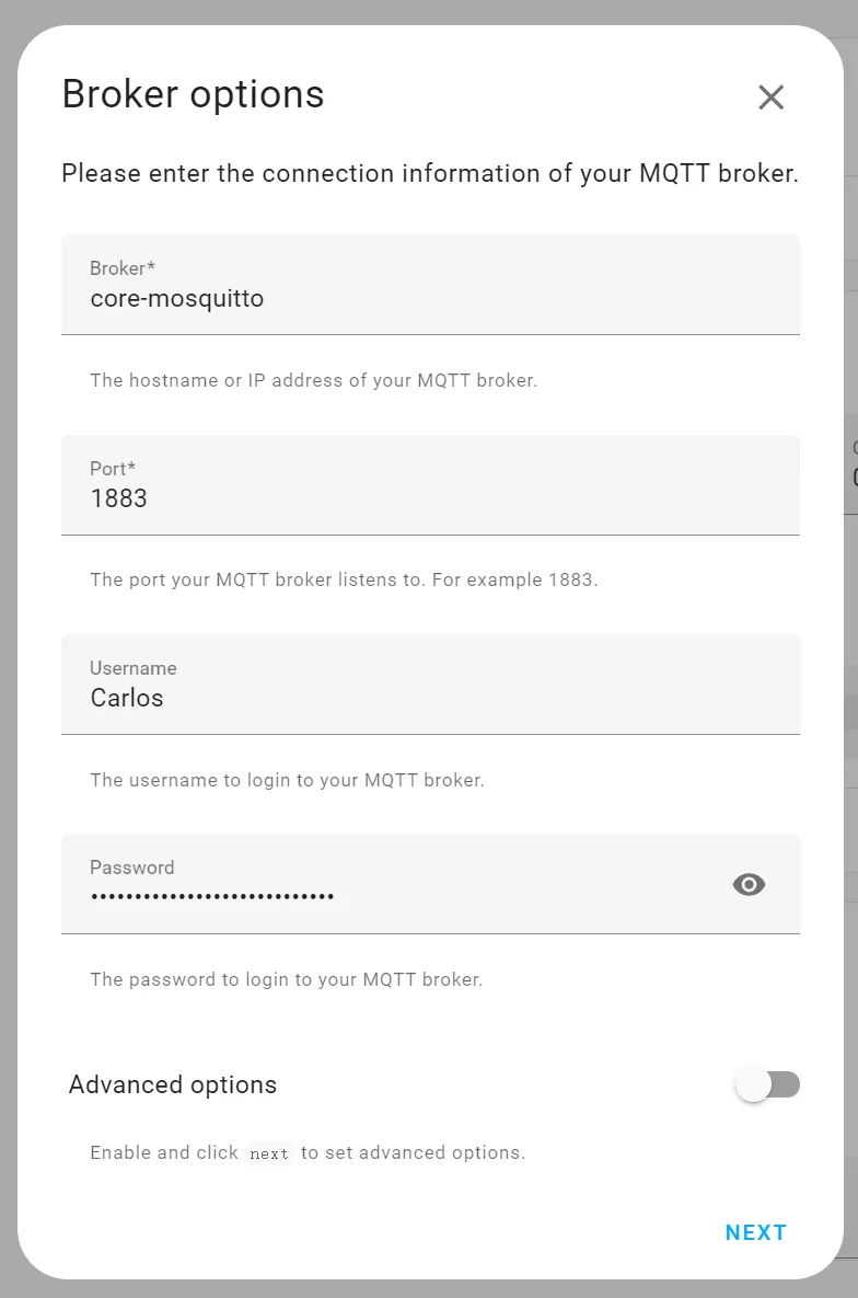
Configure the MQTT server information
- the Broker is the IP address of the Raspberry Pi server
- the default port is 1883, it can be customized
- the username and password are the username and password configured in step 6
-
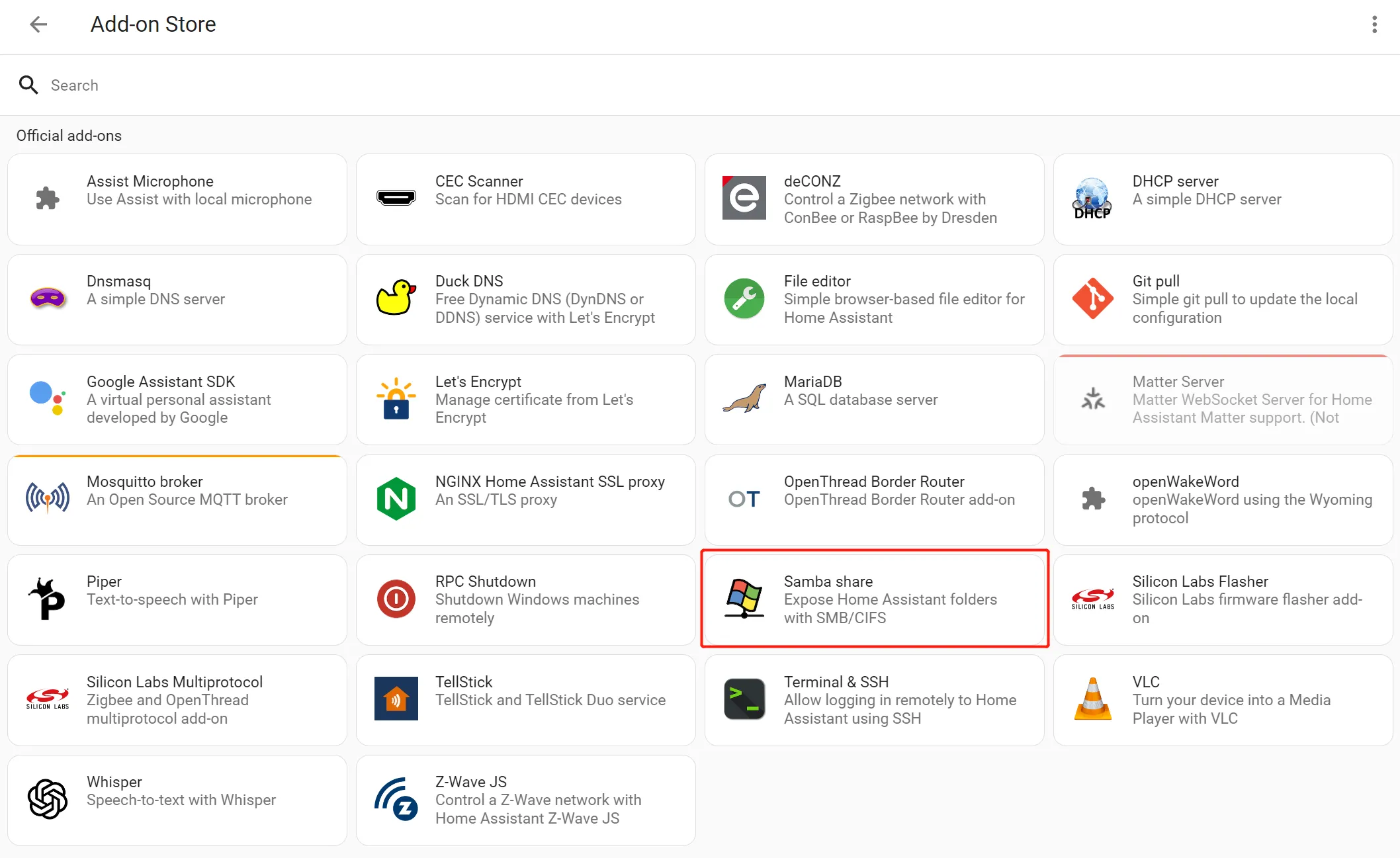
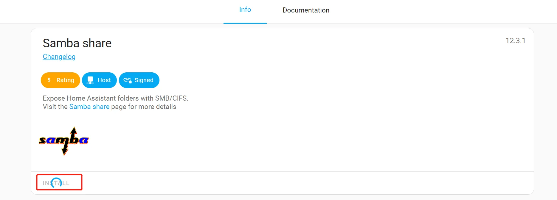
Click "Setting" -> "Add on" -> "ADD-ON STORE", and install Samba share
-
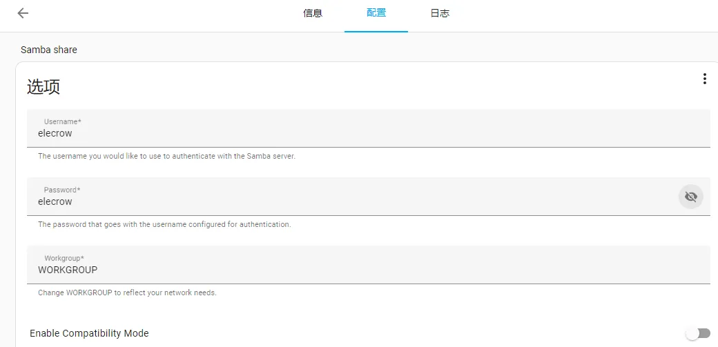
Enter the Samba share Configuration and enter the Username and Password
Tutorial on Arduino IDE
Requirements for the relevant version of the routine
Board Version
esp32 by Espressif System 2.0.14/2.0.15
The libs are provided directly by our wiki, just use the libs provided by the wiki.
Get Started with Arduino IDE
Please click the card below to learn how to install Arduino IDE, and install ESP32 board in the Arduino IDE.
Upload the MQTT Code to ESP32 Board
Please click  to download the 12.8(R)-inch ESP32 display Arduino Code.
-
Install libraries.
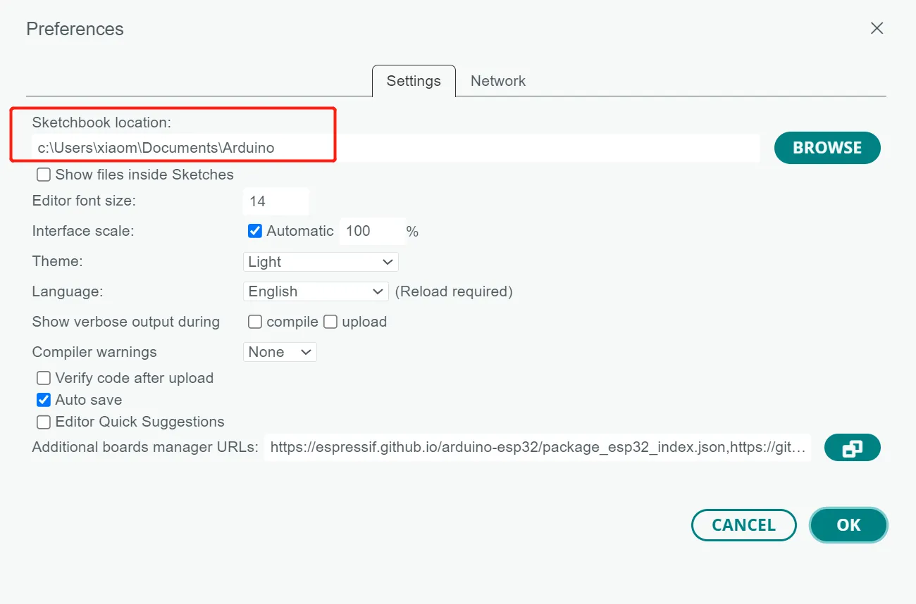
Copy the libraries folder we provided to the Sketchbook location.
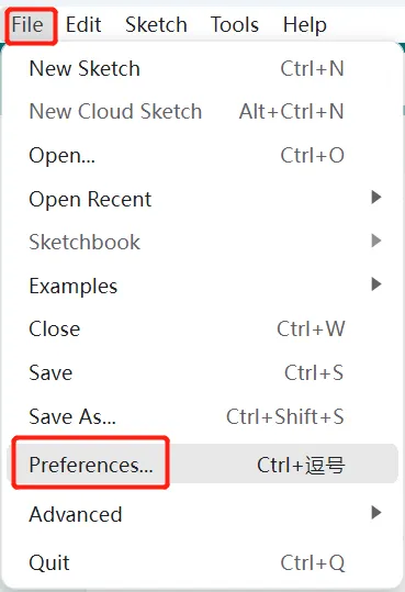
To find the Sketchbook location, please open the Arduino IDE, click "File"->"Preferences"->"Sketchbook Location".
-
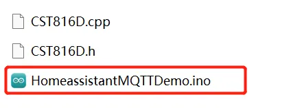
Enter the "HomeassistantMQTTDemo" folder and open HomeassistantMQTTDemo.ino
-
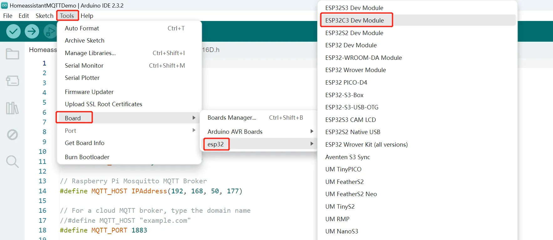
Click "Tool" -> "Board", and select the "ESP32C3 Dev Module"
-
Connect the ESP32 1.28(R) display to the computer, and click "Tool"->"Port" to select the corresponding port number.
-
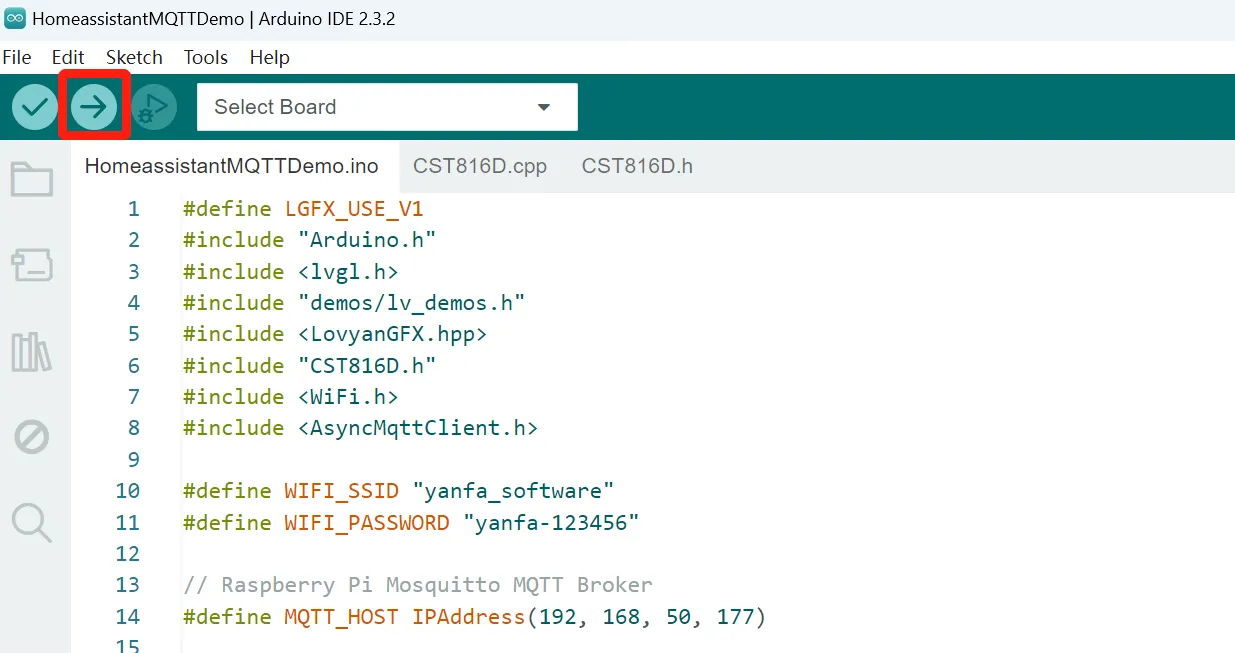
Click the "Upload" icon to upload the code. After the program is successfully downloaded, it will be prompted that the download is successful.
Connect with Home Assistant
-
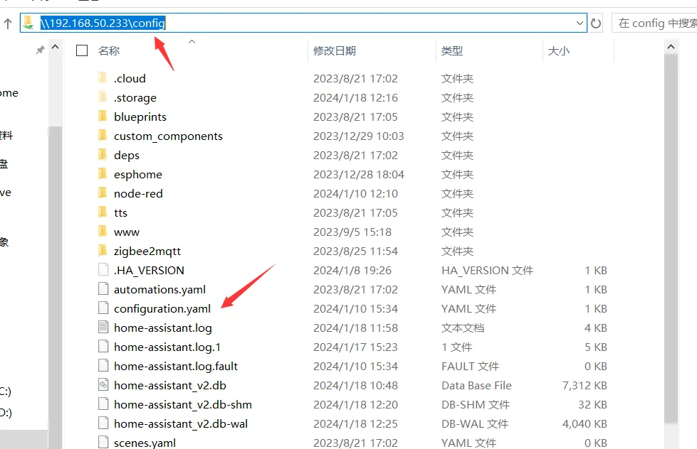
Open "File Explorer" and type in
\\192.168.50.233to enter "config" folder. Open configuration.yaml -
Add the following code in configuration.yaml to add the sensors.
mqtt: switch: - unique_id: Button name: Button state_topic: esp32/VibrationMotor/state command_topic: esp32/VibrationMotor/command payload_on: "ON" payload_off: "OFF"- Please note the format indentation.
- The above is about enabling sensors in the yaml file configuration. For more information, please refer to the link: https://www.home-assistant.io/integrations/light.mqtt/.
- Note: After configuring the yaml file, you need to restart Homeassistant to update the configuration. It is recommended to use the default qos 0 in the configuration.
-
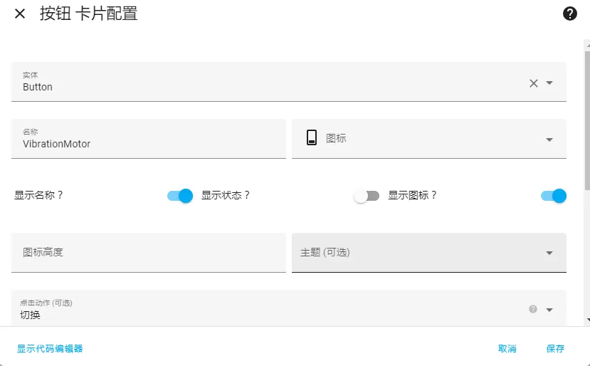
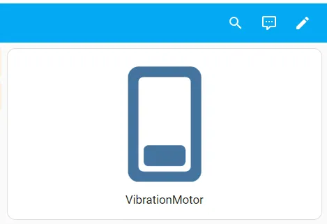
After saving the above code, go to the homepage -> Overview -> Edit Dashboard -> Add Card -> Select the entity just written in configuration.yaml in the card, the save.
-
You can control the 1.28-inch screen onboard vibration motor through the server
Examples Tutorial
Example 1 Detect the on board button status
Upload the Button.ino code to the board
// Define the pin number for the button
const int buttonPin = 1;  // The pin number where the button is connected

// Variable to store the current state of the button
int buttonState = 0;  // Variable to hold the button's state, initially set to HIGH (0)

void setup() {
  Serial.begin(115200);  // Initialize serial communication at a baud rate of 115200
  pinMode(buttonPin, INPUT);  // Set the button pin as an input
}

void loop() {
  // Read the current state of the button (HIGH or LOW)
  buttonState = digitalRead(buttonPin);

  // If the button is pressed (connected to ground, state is LOW)
  if (buttonState == LOW) {
    Serial.println("Button Press");  // Print a message when the button is pressed
  }
  // If the button is not pressed, it is in the release state (HIGH)
  else {
    Serial.println("Button release");  // Print a message when the button is released
  }

  // Note: This loop will continuously read the button state and print messages.
  // This may not be the desired behavior in all applications.
  // Consider adding a delay or using a debouncing method for the button.
}
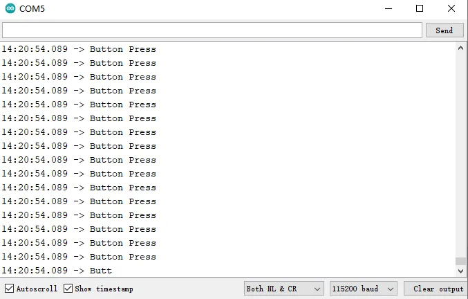
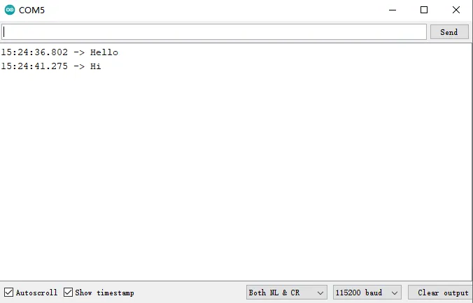
Open the serial monitor and press the button, the status of the button will be printed.
Example 2 Read the value of the encoder
Upload the Encoder.ino to the board
// Encoder defines
#define ENCODER_A_PIN 19  // Pin definition for Encoder input A
#define ENCODER_B_PIN 18  // Pin definition for Encoder input B
#define SWITCH_PIN    8    // Pin definition for Switch

bool switchPressed = false;  // Variable to track switch state
long position_tmp = 0;       // Temporary variable to hold encoder position

// Encoder update function to track changes in encoder state
void updateEncoder() {
  static int previousState = 0;  // Hold the previous state of the encoder pins
  static int flag_A = 0;         // Counter for 'forward' direction
  static int flag_C = 0;         // Counter for 'reversal' direction

  int currentState = (digitalRead(ENCODER_A_PIN) << 1) | digitalRead(ENCODER_B_PIN);  // Read the current state of the encoder

  // Check for 'forward' direction logic
  if ((currentState == 0b00 && previousState == 0b01) ||
      (currentState == 0b01 && previousState == 0b11) ||
      (currentState == 0b11 && previousState == 0b10) ||
      (currentState == 0b10 && previousState == 0b00)) {
    flag_A++;
    if (flag_A == 50) {
      flag_A = 0;
      flag_C = 0;
      position_tmp = 1;
      Serial.println("forward");  // Print out the direction
    }
  }
  // Check for 'reversal' direction logic
  else if ((currentState == 0b01 && previousState == 0b00) ||
           (currentState == 0b11 && previousState == 0b01) ||
           (currentState == 0b10 && previousState == 0b11) ||
           (currentState == 0b00 && previousState == 0b10)) {
    flag_C++;
    if (flag_C == 50) {
      flag_C = 0;
      flag_A = 0;
      position_tmp = 0;
      Serial.println("reversal");  // Print out the direction
    }
  }

  previousState = currentState;  // Update the previous state
}

// Interrupt function for switch press
void switchPressedInterrupt() {
  switchPressed = !switchPressed;  // Toggle the switchPressed state
  if (switchPressed) {
    Serial.println("press");  // Indicate switch press
  } else {
    Serial.println("release");  // Indicate switch release
  }
}

void setup() {
  Serial.begin(115200);  // Start serial communication
  pinMode(ENCODER_A_PIN, INPUT_PULLUP);  // Set encoder pins as input with pull-up
  pinMode(ENCODER_B_PIN, INPUT_PULLUP);
  pinMode(SWITCH_PIN, INPUT_PULLUP);

  // Attach interrupts for encoder and switch
  attachInterrupt(digitalPinToInterrupt(ENCODER_A_PIN), updateEncoder, CHANGE);
  attachInterrupt(digitalPinToInterrupt(ENCODER_B_PIN), updateEncoder, CHANGE);
  attachInterrupt(digitalPinToInterrupt(SWITCH_PIN), switchPressedInterrupt, FALLING);
}

void loop() {
  // Main loop, currently does nothing but wait
  delay(10);
}
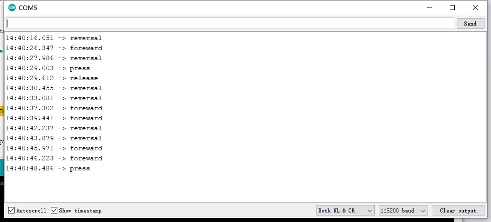
Open the serial monitor and toggle the encoder, the status of the encoder will be printed.
Example 3 Control the Buzzer
Upload the Passive_Buzzer.ino to the board
// Define the pin number for the buzzer
#define BUZZER 3

void setup() {
  // This code runs once at the beginning of the program:
  pinMode(BUZZER, OUTPUT);  // Set the buzzer pin as an output
  digitalWrite(BUZZER, LOW);  // Initially set the buzzer to a low state (off)
}

void loop() {
  // This code runs repeatedly after the setup():
  tone(BUZZER, 100);  // Make the buzzer produce a tone at a frequency of 100 Hz
  delay(1000);  // Wait for one second
  tone(BUZZER, 0);  // Stop the buzzer from producing sound (frequency set to 0)
  delay(1000);  // Wait for another second
}
The on-board buzzer will enter a cycle of beeping for one second and stopping for one second.
Example 4 Read RTC time
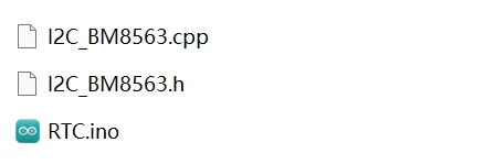
Open the RTC.ino in the "RTC" folder.
Upload the RTC.ino code to the board
#include "I2C_BM8563.h"

#define I2C_SDA 4  // Define the SDA pin for I2C communication
#define I2C_SCL 5  // Define the SCL pin for I2C communication

I2C_BM8563 rtc(I2C_BM8563_DEFAULT_ADDRESS, Wire);  // Create an RTC object using the default I2C address and Wire library
I2C_BM8563_DateTypeDef dateStruct;  // Define a structure to hold the date information
I2C_BM8563_TimeTypeDef timeStruct;  // Define a structure to hold the time information

// Function to initialize the RTC
void RTC_init() {
  rtc.begin();  // Begin communication with the RTC
  // The following lines are commented out and provided as an example
  // of how to set a custom time and date if needed:
  /*
  I2C_BM8563_TimeTypeDef timeStruct;  // Define a time structure
  timeStruct.hours   = 11;    // Set the hour (0 - 23)
  timeStruct.minutes = 59;   // Set the minute (0 - 59)
  timeStruct.seconds = 0;    // Set the second (0 - 59)
  rtc.setTime(&timeStruct);  // Set the time in the RTC
  */
  /*
  I2C_BM8563_DateTypeDef dateStruct;  // Define a date structure
  dateStruct.weekDay = 3;    // Set the weekday (0 - 6, where 0 is Sunday)
  dateStruct.month   = 1;    // Set the month (1 - 12)
  dateStruct.date    = 24;   // Set the day of the month (1 - 31)
  dateStruct.year    = 2024; // Set the year
  rtc.setDate(&dateStruct);  // Set the date in the RTC
  */
}

void setup() {
  Serial.begin(115200);  // Start serial communication at 115200 baud rate
  Wire.begin(I2C_SDA, I2C_SCL);  // Initialize the I2C bus with defined SDA and SCL pins
  RTC_init();  // Call the RTC initialization function
}

void loop() {
  rtc.getDate(&dateStruct);  // Get the current date from the RTC
  rtc.getTime(&timeStruct);  // Get the current time from the RTC
  // Print the current time in a formatted manner
  Serial.printf("The update time is: %02d:%02d:%02d\n",
                timeStruct.hours,
                timeStruct.minutes,
                timeStruct.seconds
               );
  delay(1000);  // Wait for 1 second before updating the time again
}
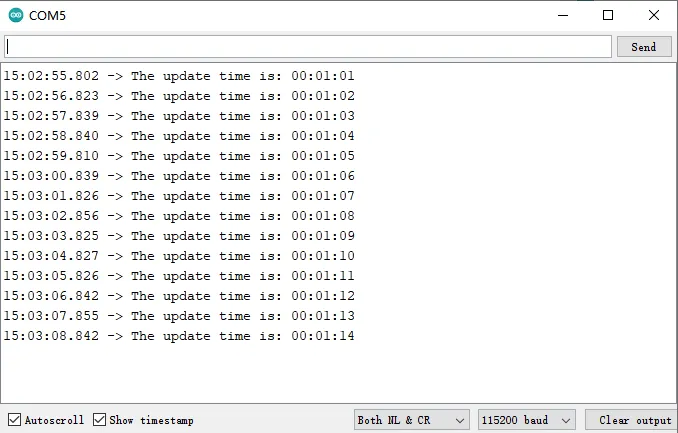
Open the serial monitor, the time will be printed.
Example 5 Control Vibration Motor
Upload the Vibration_Motor.ino code to the board
#include <Wire.h>

#define PI4IO_I2C_ADDR 0x43  // I2C address for the I/O extender

// Function to initialize the I/O extender
void init_IO_extender() {
  Wire.beginTransmission(PI4IO_I2C_ADDR);  // Start I2C transmission to the extender
  Wire.write(0x01);  // Select the test register
  Wire.endTransmission();  // End the transmission
  Wire.requestFrom(PI4IO_I2C_ADDR, 1);  // Request 1 byte from the extender
  uint8_t rxdata = Wire.read();  // Read the received data
  Serial.print("Device ID: ");
  Serial.println(rxdata, HEX);  // Print the device ID in hexadecimal

  Wire.beginTransmission(PI4IO_I2C_ADDR);  // Start I2C transmission again
  Wire.write(0x03);  // Select the I/O direction register
  Wire.write((1 << 0) | (1 << 1) | (1 << 2) | (1 << 3) | (1 << 4));  // Set pins 0-4 as outputs
  Wire.endTransmission();  // End the transmission

  Wire.beginTransmission(PI4IO_I2C_ADDR);  // Start I2C transmission
  Wire.write(0x07);  // Select the Output Hi-Z register
  Wire.write(~((1 << 0) | (1 << 1) | (1 << 2) | (1 << 3) | (1 << 4)));  // Set pins 0-4 low
  Wire.endTransmission();  // End the transmission
}

// Function to set the state of a specific pin on the I/O extender
void set_pin_io(uint8_t pin_number, bool value) {
  Wire.beginTransmission(PI4IO_I2C_ADDR);  // Start I2C transmission
  Wire.write(0x05);  // Select the test register
  Wire.endTransmission();  // End the transmission
  Wire.requestFrom(PI4IO_I2C_ADDR, 1);  // Request 1 byte from the extender
  uint8_t rxdata = Wire.read();  // Read the received data
  Serial.print("Before the change: ");
  Serial.println(rxdata, HEX);  // Print the data before change

  Wire.beginTransmission(PI4IO_I2C_ADDR);  // Start I2C transmission
  Wire.write(0x05);  // Select the Output register

  if (!value) {
    Wire.write((~(1 << pin_number)) & rxdata);  // Set the pin low
  } else {
    Wire.write((1 << pin_number) | rxdata);  // Set the pin high
  }
  Wire.endTransmission();  // End the transmission

  // Read the output state to verify the change
  Wire.beginTransmission(PI4IO_I2C_ADDR);
  Wire.write(0x05);
  Wire.endTransmission();
  Wire.requestFrom(PI4IO_I2C_ADDR, 1);
  rxdata = Wire.read();
  Serial.print("after the change: ");
  Serial.println(rxdata, HEX);  // Print the data after change
}

void setup() {
  Serial.begin(115200);  // Start serial communication at 115200 baud rate
  Wire.begin(4, 5);  // Initialize I2C bus with SDA and SCL pins
  init_IO_extender();  // Initialize the I/O extender
  delay(100);  // Short delay
}

void loop() {
  // Main code to run repeatedly
  set_pin_io(0, true);  // Set pin 0 to high
  delay(1000);  // Wait for 1000 milliseconds
  set_pin_io(0, false);  // Set pin 0 to low
  delay(1000);  // Wait for another 1000 milliseconds
}
The on-board vibration motor will enter a cycle of vibrating for one second and stopping for one second.
Example 6 Utilization of the Serial Port
Upload the code Uart.ino to the board
char val;  // Variable to store the read value from the serial buffer

void setup() {
  Serial.begin(115200);  // Initialize the serial communication at a baud rate of 115200
}

void loop() {
  // Check if there is data available in the serial buffer
  if (Serial.available()) {
    val = Serial.read();  // Read the data from the buffer and store it in 'val'
    Serial.print(val);  // Print the read character back to the serial monitor
  }
}
This code snippet sets up a simple serial communication where the Arduino board listens for incoming serial data. When data is available, it reads the first byte of data, stores it in the variable val, and then prints it back to the serial monitor. This process continues to loop, allowing for real-time data reading and echoing.
Example 7 The use of WiFi's AP (Access Point) mode
Upload the Wifi_AP.ino to the board
#include "WiFi.h"  // Include the WiFi library for ESP32

void setup() {
  Serial.begin(115200);  // Start the serial communication at a baud rate of 115200
  WiFi.softAP("ESP32C3_AP", "12345678");  // Set up the ESP32 as an Access Point with the SSID "ESP32C3_AP" and password "12345678"
}

void loop() {
  Serial.print("Host Name:");  // Print the host name of the ESP32
  Serial.println(WiFi.softAPgetHostname());
  Serial.print("Host IP Address:");  // Print the IP address of the Access Point
  Serial.println(WiFi.softAPIP());
  Serial.print("Host IPV6:");  // Print the IPv6 address of the Access Point
  Serial.println(WiFi.softAPIPv6());
  Serial.print("Host SSID:");  // Print the SSID of the Access Point
  Serial.println(WiFi.SSID());
  Serial.print("Host Broadcast IP:");  // Print the broadcast IP address of the Access Point
  Serial.println(WiFi.softAPBroadcastIP());
  Serial.print("Host Mac Address:");  // Print the MAC address of the Access Point
  Serial.println(WiFi.softAPmacAddress());
  Serial.print("Number Of Host Connections:");  // Print the number of devices connected to the Access Point
  Serial.println(WiFi.softAPgetStationNum());
  Serial.print("Host Network ID:");  // Print the network ID
  Serial.println(WiFi.softAPNetworkID());
  Serial.print("Host State:");  // Print the current state of the WiFi host (Access Point)
  Serial.println(WiFi.status());
  delay(1000);  // Wait for 1 second before printing the information again
}
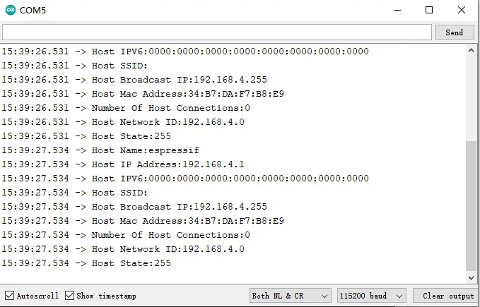
This code sets up an ESP32 device as a WiFi Access Point with a specified SSID and password. In the loop() function, it prints various details about the Access Point, such as the host name, IP address, IPv6 address, SSID, broadcast IP, MAC address, number of connected clients, network ID, and the current WiFi state. This information is printed to the serial monitor every second.
Example 8 The use of WiFi's STA (Station) mode
Upload the Wifi_STA.ino to the board
#include "WiFi.h"  // Include the WiFi library for ESP8266 or ESP32

void setup() {
  Serial.begin(115200);  // Initialize serial communication at a baud rate of 115200

  // Start WiFi connection with given SSID and password
  WiFi.begin("elecrow-test", "1223334444");
  // Enable auto-reconnect feature
  WiFi.setAutoReconnect(true);
}

void loop() {
  // Print the connection status: true if connected, false otherwise
  Serial.print("Connection Status:");
  Serial.println(WiFi.isConnected());
  // Print the local IP address of the device
  Serial.print("Local IP:");
  Serial.println(WiFi.localIP());
  // Print the local IPv6 address of the device
  Serial.print("Local IPv6:");
  Serial.println(WiFi.localIPv6());
  // Print the MAC address of the device
  Serial.print("Mac Address:");
  Serial.println(WiFi.macAddress());
  // Print the network ID
  Serial.print("Network ID:");
  Serial.println(WiFi.networkID());
  // Print the sleep mode setting
  Serial.print("Sleep:");
  Serial.println(WiFi.getSleep());
  // Print the WiFi status bits
  Serial.print("Get Status:");
  Serial.println(WiFi.getStatusBits());
  // Print the transmission power setting
  Serial.print("Get Tx Power:");
  Serial.println(WiFi.getTxPower());
  // Print the auto connect setting
  Serial.print("get Auto Connect:");
  Serial.println(WiFi.getAutoConnect());
  // Print the auto reconnect setting
  Serial.print("Get Auto Reconnect:");
  Serial.println(WiFi.getAutoReconnect());
  // Print the current WiFi mode (1 - WIFI_OFF, 2 - WIFI_STA, 3 - WIFI_AP, 4 - WIFI_AP_STA)
  Serial.print("Get Mode:");
  Serial.println(WiFi.getMode());
  // Print the device's hostname
  Serial.print("Get Hostname:");
  Serial.println(WiFi.getHostname());
  // Print the gateway IP address
  Serial.print("Gateway IP:");
  Serial.println(WiFi.gatewayIP());
  // Print the DNS server IP address
  Serial.print("dns IP:");
  Serial.println(WiFi.dnsIP());
  // Print the current WiFi status
  Serial.print("Status:");
  Serial.println(WiFi.status());
  delay(1000);  // Wait for 1 second before printing the information again
}
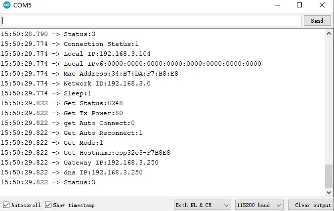
This code initializes the WiFi module to connect to a network with the specified SSID and password and enables auto-reconnect. In the loop() function, it prints various WiFi-related details such as connection status, IP addresses, MAC address, network ID, sleep mode, transmission power, auto connect and reconnect settings, WiFi mode, hostname, gateway IP, DNS IP, and the current status. The information is printed to the serial monitor every second.
Example 9 Using WiFi in STA (Station) mode as a TCP client
Upload the code WIFI_STA_TCP_Client to the board
#include <WiFi.h>

const char *ssid = "elecrow-test";  // The SSID of the WiFi network to connect to
const char *password = "1223334444";  // The password of the WiFi network

const IPAddress serverIP(192, 168, 3, 105);  // The IP address of the server to connect to
uint16_t serverPort = 9527;  // The port number on the server to connect to

WiFiClient client;  // Create an instance of the WiFiClient class to create a TCP connection

void setup() {
  Serial.begin(115200);  // Start the serial communication at a baud rate of 115200
  delay(1000);  // Delay for 1000 milliseconds to give the serial console time to initialize
  WiFi.begin(ssid, password);  // Initiate a connection to the WiFi network
  // Wait for the WiFi connection to be established
  while (WiFi.status() != WL_CONNECTED) {
    delay(1000);
    Serial.print(".");
  }
  Serial.println("Connected");  // Print a message to indicate the connection is established
  Serial.print("IP Address:");  // Print the IP address assigned to the device
  Serial.println(WiFi.localIP());
}

void loop() {
  // Attempt to establish a TCP connection with the server
  if (client.connect(serverIP, serverPort)) {
    client.print("Hello world!");  // Send a "Hello world!" message to the server
    // Keep the connection open and interact with the server
    while (client.connected() || client.available()) {
      if (client.available()) {  // Check if there is data available from the server
        String line = client.readStringUntil('\n');  // Read a line of data from the server
        Serial.print("Read data:");  // Print a message indicating data was read
        Serial.println(line);
        client.write(line.c_str());  // Echo the received data back to the server
      }
    }
    Serial.println("Close Current Connection");  // Print a message indicating the connection is closed
    client.stop();  // Close the TCP connection
  } else {
    Serial.println("Access Failure");  // Print a message indicating the connection failed
    client.stop();  // Ensure the client stops any attempt to connect
  }
  delay(5000);  // Wait for 5000 milliseconds before attempting to reconnect
}
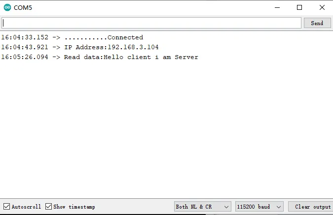
This code sets up an ESP32 device to connect to a specified WiFi network in Station (STA) mode and then attempts to establish a TCP connection with a server. If the connection is successful, it sends a "Hello world!" message and then enters a loop to interact with the server, reading and echoing data until the connection is closed or fails. If the connection cannot be established, it prints an error message and waits for 5 seconds before trying again.
Example 10 Using WiFi in STA (Station) mode as a TCP server
Upload the code WIFI_STA_TCP_Server to the board
#include <WiFi.h>         // Include the WiFi library for ESP8266 or ESP32
#include <WiFiClient.h>   // Include the WiFiClient library for client functionality

const char* ssid = "elecrow-test";  // The SSID of the WiFi network
const char* password = "1223334444";  // The password of the WiFi network

WiFiServer server(1234);  // Create a WiFiServer object to handle incoming TCP connections on port 1234

void setup() {
  Serial.begin(115200);  // Start the serial communication at a baud rate of 115200
  delay(1000);            // Delay for 1000 milliseconds to ensure the serial port is ready
  WiFi.begin(ssid, password);  // Initiate a connection to the WiFi network
  // Wait for the WiFi connection to be established
  while (WiFi.status() != WL_CONNECTED) {
    delay(1000);
    Serial.println("Connecting to WiFi...");
  }
  server.begin();  // Start the server to listen for incoming connections
  Serial.println("WiFi connected");
  Serial.println("IP address: " + WiFi.localIP().toString());  // Print the IP address of the device
}

void loop() {
  // Check if there is a new client that has connected
  WiFiClient client = server.available();
  if (client) {
    Serial.println("New client connected");
    // Keep the connection open while the client is connected
    while (client.connected()) {
      if (client.available()) {  // Check if there is data available from the client
        String data = client.readStringUntil('\n');  // Read a line of data sent by the client
        Serial.print("Received data: ");
        Serial.println(data);  // Print the received data
        String response = "Server received: " + data;  // Create a response string
        client.println(response);  // Send the response back to the client
      }
    }
    client.stop();  // Close the connection once the client disconnects
    Serial.println("Client disconnected");
  }
}
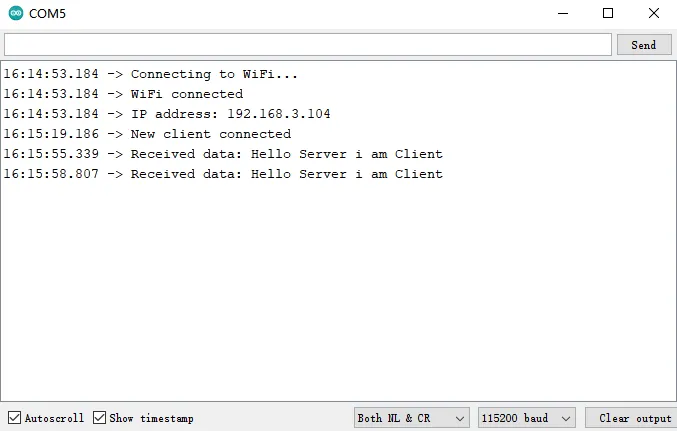
This code sets up an ESP32 device to connect to a specified WiFi network in Station mode and then starts a TCP server on port 1234. When a new client connects, the server accepts the connection and waits for data from the client. When data is received, it is echoed back to the client along with a message indicating that the server has received it. The connection is closed when the client disconnects.
Example 11 Utilizing WiFi in Station (STA) mode to implement UDP (User Datagram Protocol)
Upload the code WIFI_STA_UDP to the board
#include <WiFi.h>
#include <AsyncUDP.h>

const char *ssid = "elecrow-test";  // SSID of the WiFi network
const char *password = "1223334444";  // Password of the WiFi network

AsyncUDP udp;  // Create an AsyncUDP object for handling UDP packets
unsigned int localUdpPort = 9527;  // Local UDP port number

unsigned int broadcastPort = localUdpPort;  // Port number for broadcasting
const char *broadcastData = "from esp32c3";  // Data to be sent as broadcast

// Callback function for handling incoming UDP packets
void onPacketCallBack(AsyncUDPPacket packet) {
  Serial.print("UDP packet source type: ");
  Serial.println(packet.isBroadcast() ? "broadcast data" : (packet.isMulticast() ? "Multicast" : "Unicast"));
  Serial.print("Remote address and port number: ");
  Serial.print(packet.remoteIP());
  Serial.print(":");
  Serial.println(packet.remotePort());
  Serial.print("Destination address and port number: ");
  Serial.print(packet.localIP());
  Serial.print(":");
  Serial.println(packet.localPort());
  Serial.print("data length: ");
  Serial.println(packet.length());
  Serial.print("data content: ");
  Serial.write(packet.data(), packet.length());
  Serial.println();
  // Send a reply back to the source of the packet
  packet.print("reply data");
  broadcastPort = packet.remotePort();  // Update the broadcast port to the remote port
}

void setup() {
  Serial.begin(115200);  // Start serial communication
  WiFi.begin(ssid, password);  // Initiate WiFi connection
  // Wait for WiFi to connect
  while (!WiFi.isConnected()) {
    delay(1000);
    Serial.print(".");
  }
  Serial.println("Connected");
  Serial.print("IP Address:");
  Serial.println(WiFi.localIP());  // Print the assigned IP address

  // Start listening for UDP packets on the local port
  while (!udp.listen(localUdpPort)) {
  }
  // Set the callback function to be called when a packet is received
  udp.onPacket(onPacketCallBack);
}

void loop() {
  delay(5000);  // Wait for 5 seconds

  // Send a broadcast message to the previously received remote port
  udp.broadcastTo(broadcastData, broadcastPort);
  // The following lines are commented out as they are not used in this example
  /*
  IPAddress broadcastAddr((~(uint32_t)WiFi.subnetMask())|((uint32_t)WiFi.localIP()));
  udp.writeTo(broadcastData, sizeof(broadcastData), broadcastAddr, localUdpPort);
  */
}
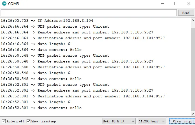
This code sets up an ESP32 device to connect to a WiFi network in Station mode and then listens for incoming UDP packets on a specified local port using the AsyncUDP library. When a packet is received, it is handled by the onPacketCallBack function, which prints details about the packet and sends a reply back to the sender. The loop() function sends a broadcast message every 5 seconds to the port number from which the last received packet originated. The commented lines provide an alternative method for sending a broadcast message using a calculated broadcast address, but they are not used in this example.
Example 12 Using Bluetooth services in Bluetooth mode
Upload the code BLE_Server.ino to the CrowPanel ESP32 Display 1.28(R) Inch-WATCH.
#include <BLEDevice.h>
#include <BLEUtils.h>
#include <BLEServer.h>

#define SERVICE_UUID        "4fafc201-1fb5-459e-8fcc-c5c9c331914b"  // UUID for the service
#define CHARACTERISTIC_UUID "beb5483e-36e1-4688-b7f5-ea07361b26a8"  // UUID for the characteristic

BLECharacteristic *pCharacteristic;  // Pointer to the BLE characteristic

void setup() {
  Serial.begin(115200);  // Initialize serial communication at a baud rate of 115200
  BLEDevice::init("ESP32C3_BLE_Server");  // Initialize the BLE device with a name
  BLEServer *pServer = BLEDevice::createServer();  // Create a BLE server
  BLEService *pService = pServer->createService(SERVICE_UUID);  // Create a service with the specified UUID

  // Create a characteristic with read and notify properties
  pCharacteristic = pService->createCharacteristic(
                       CHARACTERISTIC_UUID,
                       BLECharacteristic::PROPERTY_READ |
                       BLECharacteristic::PROPERTY_NOTIFY
                     );

  pCharacteristic->setValue("Hello World");  // Set the initial value of the characteristic
  pService->start();  // Start the service
  pServer->getAdvertising()->start();  // Start advertising the BLE device
}

void loop() {
  // This loop function does nothing in this example as the BLE server does not require
  // continuous processing in the loop once it's set up and running.
}
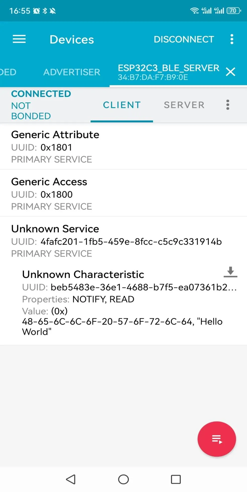
This code sets up an ESP32 device to act as a BLE (Bluetooth Low Energy) server with a single service and a single characteristic. The characteristic is set to allow both reading and notifying. The initial value of the characteristic is set to "Hello World," and the service and advertising are started. Once this setup is complete, the loop() function does not perform any additional actions, as the BLE server operates independently of the main program loop.
Example 13 Running the LVGL Widgets Demo
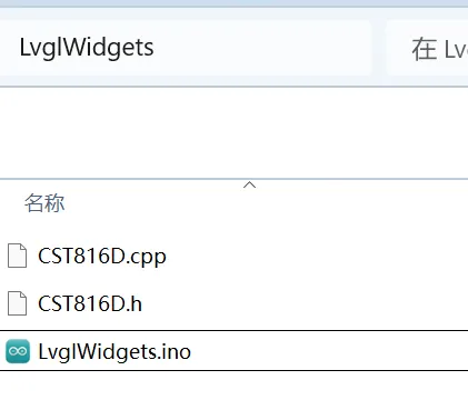
Open the LvglWidgets.ino in the LvglWidgets folder
Upload the code LvglWidgets to the CrowPanel ESP32 Display 1.28(R) Inch-WATCH
#define LGFX_USE_V1
#include "Arduino.h"
#include <lvgl.h>
#include "demos/lv_demos.h"
#include <LovyanGFX.hpp>
#include "CST816D.h"

// I2C pins
#define I2C_SDA 4
#define I2C_SCL 5
// Touch panel interrupt and reset pins
#define TP_INT 0
#define TP_RST -1

// I2C address for the I/O extender
#define PI4IO_I2C_ADDR 0x43

// Buffer size definition
#define buf_size 120

// LGFX class definition for display device interface
class LGFX : public lgfx::LGFX_Device
{
  // Internal components of the LGFX class
    lgfx::Panel_GC9A01 _panel_instance;
    lgfx::Bus_SPI _bus_instance;
  public:
    LGFX(void)
    {
      {
        // Configuration for the SPI bus and panel
        auto cfg = _bus_instance.config();
        cfg.spi_host = SPI2_HOST;
        cfg.spi_mode = 0;
        cfg.freq_write = 80000000;
        cfg.freq_read = 20000000;
        cfg.spi_3wire = true;
        cfg.use_lock = true;
        cfg.dma_channel = SPI_DMA_CH_AUTO;
        cfg.pin_sclk = 6;
        cfg.pin_mosi = 7;
        cfg.pin_miso = -1;
        cfg.pin_dc = 2;
        _bus_instance.config(cfg);
        _panel_instance.setBus(&_bus_instance);
      }
      {
        auto cfg = _panel_instance.config();
        cfg.pin_cs = 10;
        cfg.pin_rst = -1;
        cfg.pin_busy = -1;
        cfg.memory_width = 240;
        cfg.memory_height = 240;
        cfg.panel_width = 240;
        cfg.panel_height = 240;
        cfg.offset_x = 0;
        cfg.offset_y = 0;
        cfg.offset_rotation = 0;
        cfg.dummy_read_pixel = 8;
        cfg.dummy_read_bits = 1;
        cfg.readable = false;
        cfg.invert = true;
        cfg.rgb_order = false;
        cfg.dlen_16bit = false;
        cfg.bus_shared = false;
        _panel_instance.config(cfg);
      }
      setPanel(&_panel_instance);
    }
};

// Global instances for the display and touch screen
LGFX tft;
CST816D touch(I2C_SDA, I2C_SCL, TP_RST, TP_INT);

/*Change to your screen resolution*/
static const uint32_t screenWidth = 240;
static const uint32_t screenHeight = 240;

static lv_disp_draw_buf_t draw_buf;
static lv_color_t buf[2][screenWidth * buf_size];

#if LV_USE_LOG != 0
// Custom print function for LVGL debugging
void my_print(lv_log_level_t level, const char *file, uint32_t line, const char *fn_name, const char *dsc)
{
  Serial.printf("%s(%s)@%d->%s\r\n", file, fn_name, line, dsc);
  Serial.flush();
}
#endif

// Function to handle flushing of display buffer to the screen
void my_disp_flush(lv_disp_drv_t *disp, const lv_area_t *area, lv_color_t *color_p)
{
  if (tft.getStartCount() == 0)
  {
    tft.endWrite();
  }

  tft.pushImageDMA(area->x1, area->y1, area->x2 - area->x1 + 1, area->y2 - area->y1 + 1, (lgfx::swap565_t *)&color_p->full);

  lv_disp_flush_ready(disp); /* tell lvgl that flushing is done */
}

// Function to read touchpad input
void my_touchpad_read(lv_indev_drv_t *indev_driver, lv_indev_data_t *data)
{
  bool touched;
  uint8_t gesture;
  uint16_t touchX, touchY;
  touched = touch.getTouch(&touchX, &touchY, &gesture);
  if (!touched)
  {
    data->state = LV_INDEV_STATE_REL;
  }
  else
  {
    data->state = LV_INDEV_STATE_PR;
    /*Set the coordinates*/
    data->point.x = touchX;
    data->point.y = touchY;
  }
}

// Function to initialize I/O extender
void init_IO_extender() {
  Wire.beginTransmission(PI4IO_I2C_ADDR);
  Wire.write(0x01); // test register
  Wire.endTransmission();
  Wire.requestFrom(PI4IO_I2C_ADDR, 1);
  uint8_t rxdata = Wire.read();
  Serial.print("Device ID: ");
  Serial.println(rxdata, HEX);

  Wire.beginTransmission(PI4IO_I2C_ADDR);
  Wire.write(0x03); // IO direction register
  Wire.write((1 << 0) | (1 << 1) | (1 << 2) | (1 << 3) | (1 << 4)); // set pins 0, 1, 2 as outputs
  Wire.endTransmission();

  Wire.beginTransmission(PI4IO_I2C_ADDR);
  Wire.write(0x07); // Output Hi-Z register
  Wire.write(~((1 << 0) | (1 << 1) | (1 << 2) | (1 << 3) | (1 << 4))); // set pins 0, 1, 2 low
  Wire.endTransmission();
}

// Function to set I/O pin state on the extender
void set_pin_io(uint8_t pin_number, bool value) {

  Wire.beginTransmission(PI4IO_I2C_ADDR);
  Wire.write(0x05); // test register
  Wire.endTransmission();
  Wire.requestFrom(PI4IO_I2C_ADDR, 1);
  uint8_t rxdata = Wire.read();
  Serial.print("Before the change: ");
  Serial.println(rxdata, HEX);

  Wire.beginTransmission(PI4IO_I2C_ADDR);
  Wire.write(0x05); // Output register

  if (!value)
    Wire.write((~(1 << pin_number)) & rxdata); // set pin low
  else
    Wire.write((1 << pin_number) | rxdata); // set pin high
  Wire.endTransmission();

  Wire.beginTransmission(PI4IO_I2C_ADDR);
  Wire.write(0x05); // test register
  Wire.endTransmission();
  Wire.requestFrom(PI4IO_I2C_ADDR, 1);
  rxdata = Wire.read();
  Serial.print("after the change: ");
  Serial.println(rxdata, HEX);
}

void setup()
{
  // Initialization of serial communication, I2C, display, touch screen, and LVGL
  Serial.begin(115200); /* prepare for possible serial debug */
  Serial.println("I am LVGL_Arduino");
  Wire.begin(4, 5);
  init_IO_extender();
  delay(100);
  set_pin_io(3, true);
  set_pin_io(4, true);
  set_pin_io(2, true);
  tft.init();
  tft.initDMA();
  tft.startWrite();
  tft.setColor(0, 0, 0);

  tft.fillScreen(TFT_BLACK);
  delay(200);
  touch.begin();
  lv_init();
#if LV_USE_LOG != 0
  //lv_log_register_print_cb(my_print); /* register print function for debugging */
#endif

  lv_disp_draw_buf_init(&draw_buf, buf[0], buf[1], screenWidth * buf_size);

  /*Initialize the display*/
  static lv_disp_drv_t disp_drv;
  lv_disp_drv_init(&disp_drv);
  /*Change the following line to your display resolution*/
  disp_drv.hor_res = screenWidth;
  disp_drv.ver_res = screenHeight;
  disp_drv.flush_cb = my_disp_flush;
  disp_drv.draw_buf = &draw_buf;
  lv_disp_drv_register(&disp_drv);

  /*Initialize the (dummy) input device driver*/
  static lv_indev_drv_t indev_drv;
  lv_indev_drv_init(&indev_drv);
  indev_drv.type = LV_INDEV_TYPE_POINTER;
  indev_drv.read_cb = my_touchpad_read;
  lv_indev_drv_register(&indev_drv);


#if 0
  /* Create simple label */
  lv_obj_t *label = lv_label_create( lv_scr_act() );
  lv_label_set_text( label, "Hello Arduino! (V8.0.X)" );
  lv_obj_align( label, LV_ALIGN_CENTER, 0, 0 );
#else
  // uncomment one of these demos
  lv_demo_widgets(); // OK
#endif
  Serial.println("Setup done");
}


void loop()
{
  lv_timer_handler(); /* let the GUI do its work */
  delay(5);
}
The LVGL demo will show on the screen
Tutorial on Thonny IDE
Download Thonny IDE
-
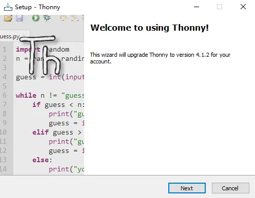
Go to the website https://thonny.org/ and download the corresponding software version (here we take the Windows version as an example)
-
Double-click the downloaded exe file to install the software.
Upload Firmware
-
Connect the 1.28(R)-inch display to the computer.
-
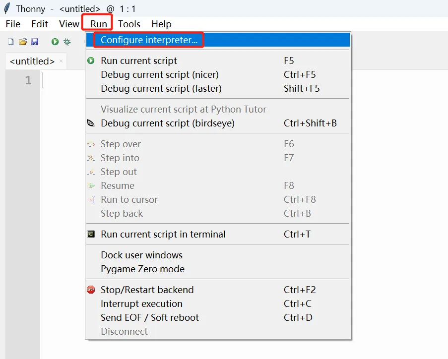
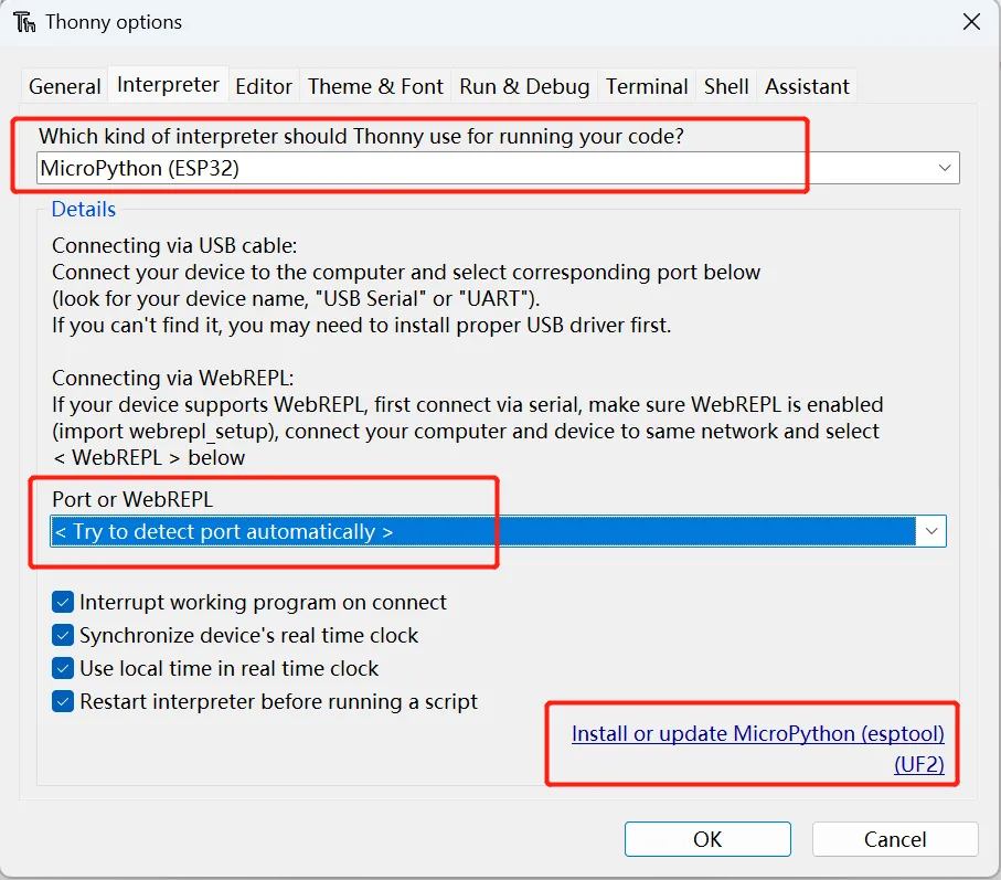
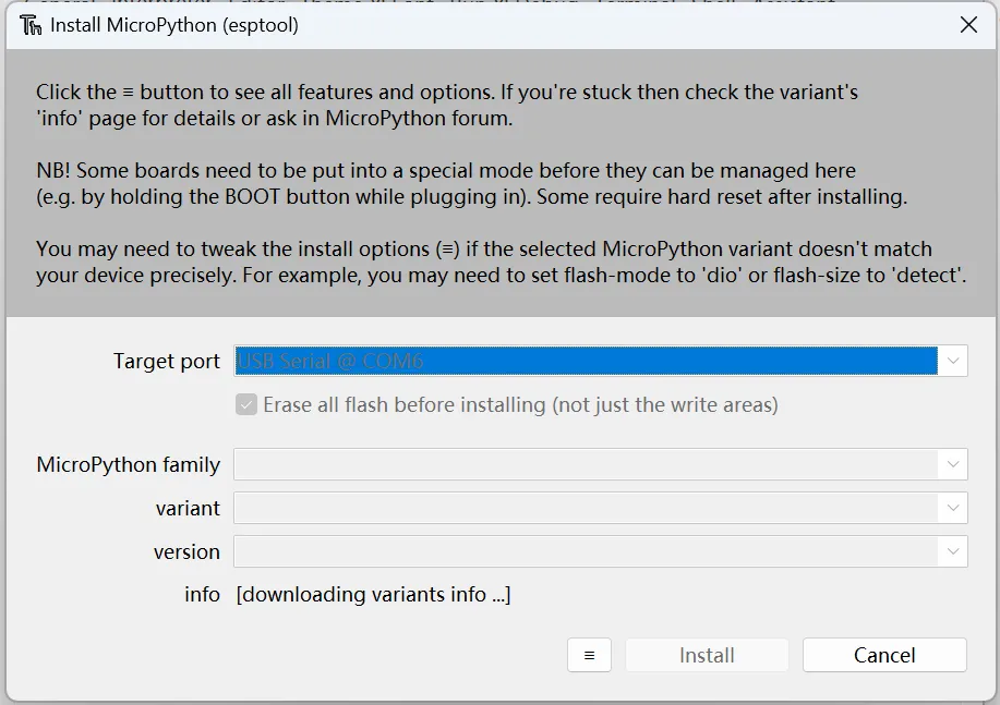
Open Thonny IDE and click "Run"->"Configure interpreter". Select "MicroPython(ESP32)" as the interpreter. Then click "Install and update MicroPython"
-
Waiting for the loading the downloading variants info...
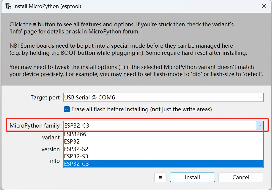
After loading is complete, select the ESP32-C3 family
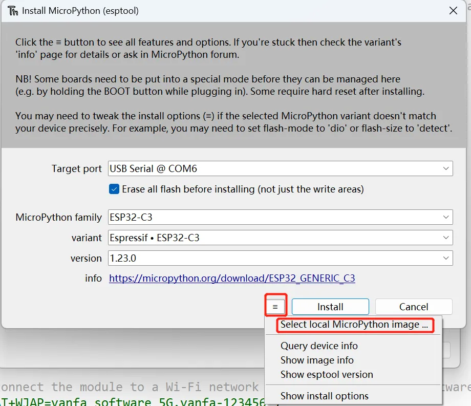
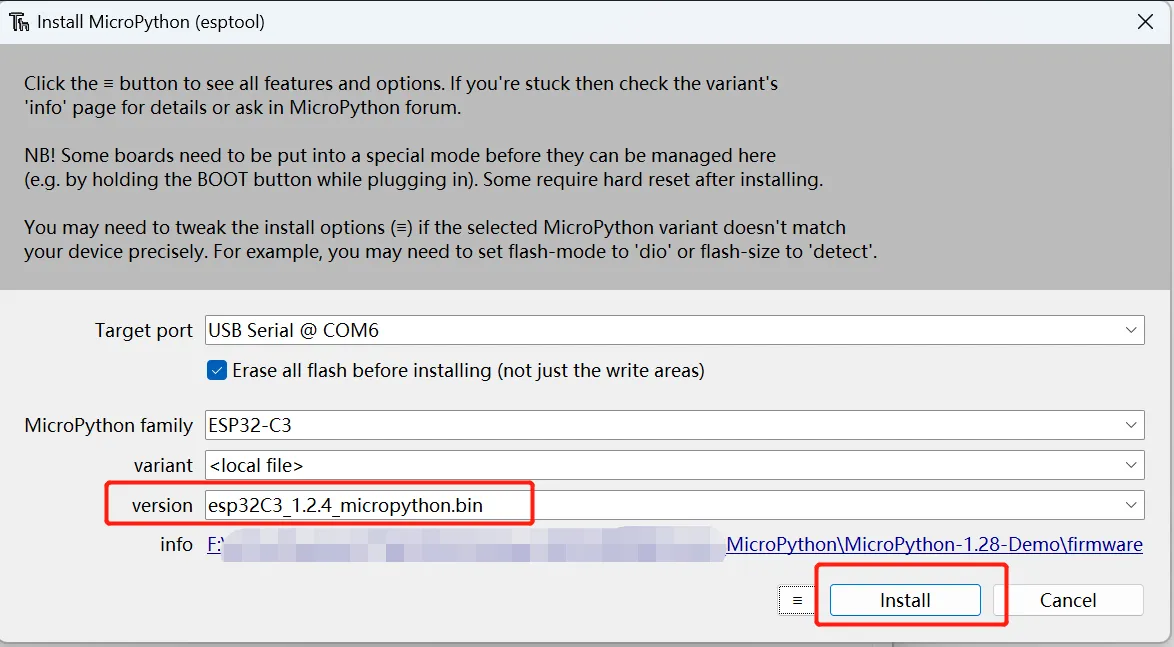
Then click the three line icon in front of the "Install" icon, click "Select local MicroPython image ..." and choose the "esp32C3_1.2.4_micropython.bin" in the firmware folder. Then click "Install".
Installation is done!
Examples on Thonny IDE
Example 1 Detect the on board button status
Run the Button.py
from machine import Pin
import time

# Set the GPIO pin number where the button is connected, GPIO 1 is used as an example
button_pin = 1

# Initialize the button, set as input mode, and enable the internal pull-up resistor
button = Pin(button_pin, Pin.IN, Pin.PULL_UP)

# Main loop, here we use polling to check if the button is being held down
while True:
    # Check if the button is pressed (read the level of the GPIO pin)
    if button.value() == 0:
        print("Button is currently pressed")
        # Additional code can be added here to handle the logic when the button is pressed
    time.sleep(0.1)  # Simple debounce delay
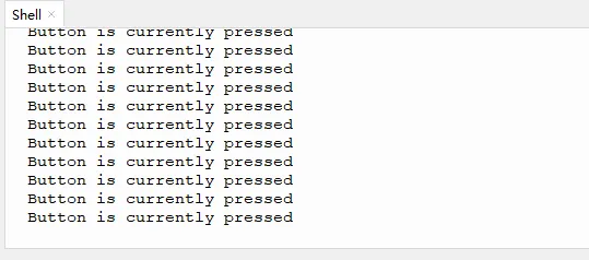
Press the button, the status of the button will be printed.
Example 2 Read the value of the encoder
-
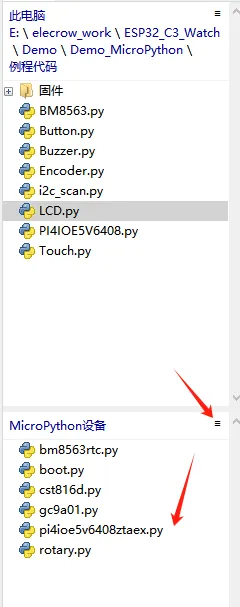
First add the rotary library
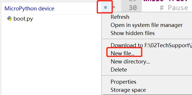
Click the menu icon at MicroPython device, and click New file...
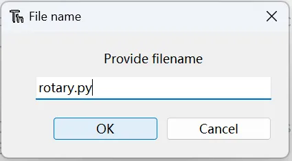
Provide a file name. Please note to add the file suffix .py
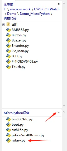
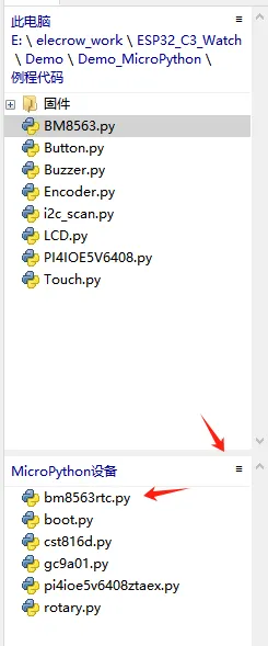
Copy the code to the editor and click run. The rotary.py will be added to the MicroPython device.
import machine import utime as time from machine import Pin import micropython class Rotary: ROT_CW = 1 ROT_CCW = 2 SW_PRESS = 4 SW_RELEASE = 8 def __init__(self,dt,clk,sw): self.dt_pin = Pin(dt, Pin.IN) self.clk_pin = Pin(clk, Pin.IN) self.sw_pin = Pin(sw, Pin.IN) self.last_status = (self.dt_pin.value() << 1) | self.clk_pin.value() self.dt_pin.irq(handler=self.rotary_change, trigger=Pin.IRQ_FALLING | Pin.IRQ_RISING ) self.clk_pin.irq(handler=self.rotary_change, trigger=Pin.IRQ_FALLING | Pin.IRQ_RISING ) self.sw_pin.irq(handler=self.switch_detect, trigger=Pin.IRQ_FALLING | Pin.IRQ_RISING ) self.handlers = [] self.last_button_status = self.sw_pin.value() def rotary_change(self, pin): new_status = (self.dt_pin.value() << 1) | self.clk_pin.value() if new_status == self.last_status: return transition = (self.last_status << 2) | new_status try: if transition == 0b1110: micropython.schedule(self.call_handlers, Rotary.ROT_CW) elif transition == 0b1101: micropython.schedule(self.call_handlers, Rotary.ROT_CCW) except RuntimeError: pass self.last_status = new_status def switch_detect(self,pin): if self.last_button_status == self.sw_pin.value(): return self.last_button_status = self.sw_pin.value() if self.sw_pin.value(): micropython.schedule(self.call_handlers, Rotary.SW_RELEASE) else: micropython.schedule(self.call_handlers, Rotary.SW_PRESS) def add_handler(self, handler): self.handlers.append(handler) def call_handlers(self, type): for handler in self.handlers: handler(type) -
Run the Encoder.py to the board
from rotary import Rotary # Import the Rotary class from the rotary module. import utime as time # Import the utime module and alias it as 'time' for timing functions. # Create a Rotary object with the pin numbers for the rotary encoder and the interrupt pin. rotary = Rotary(19, 18, 8) # Initialize a variable to store the current value of the rotary encoder. val = 0 # Define a callback function that will be called when the rotary encoder is changed. def rotary_changed(change): global val # Declare 'val' as global to modify its value inside this function. # Check the type of change and update 'val' accordingly. if change == Rotary.ROT_CW: # If the rotary was turned clockwise. val = val + 1 # Increment the value. print(val) # Print the new value. elif change == Rotary.ROT_CCW: # If the rotary was turned counter-clockwise. val = val - 1 # Decrement the value. print(val) # Print the new value. elif change == Rotary.SW_PRESS: # If the rotary switch was pressed. print('PRESS') # Print 'PRESS'. elif change == Rotary.SW_RELEASE: # If the rotary switch was released. print('RELEASE') # Print 'RELEASE'. # Add the 'rotary_changed' function as a handler for rotary events. rotary.add_handler(rotary_changed) # Main loop that keeps the program running. while True: # Pause the loop for 100 milliseconds to reduce the frequency of execution and lower CPU usage. time.sleep(0.1) -
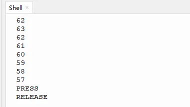
Rotate the encoder in different directions, the value will increase or decrease, pressing the button will print "press", and releasing the button will print "release"
Example 3 Control the Buzzer
Run the Buzzer.py
from machine import Pin
import time

# Define the GPIO pin number connected to the buzzer, GPIO 3 is used as an example
buzzer_pin = 3

# Create a Pin object and set it to output mode
buzzer = Pin(buzzer_pin, Pin.OUT)

# Define a function to make the buzzer beep at a certain frequency and for a certain duration
def buzz(freq, duration):
    # Calculate the period time (cycles per second)
    period = 1.0 / freq
    # Calculate the delay between interrupts (in microseconds)
    delay = int(period * 1e6)

    # Calculate the end time based on the current time and the duration
    end_time = time.ticks_ms() + duration

    # Generate a square wave signal to make the buzzer beep
    while time.ticks_ms() < end_time:
        buzzer.value(1)  # Turn on the buzzer
        time.sleep_us(delay // 2)
        buzzer.value(0)  # Turn off the buzzer
        time.sleep_us(delay // 2)

# Make the buzzer beep at a frequency of 1000Hz for a duration of 2000 milliseconds (2 seconds)
buzz(1000, 2000)
The on-board buzzer will sound at a frequency of 1000Hz for 2 seconds
Example 4 Read RTC time
-
Add library
Add bm8563rtc.py to the MicroPython device in the same way as in Example 2
from micropython import const _PCF8563_I2C_DEFAULT_ADDR = const(0x51) _PCF8563_CONTROL_STATUS1 = const(0x00) _PCF8563_CONTROL_STATUS1_TEST1 = const(0b1000_0000) _PCF8563_CONTROL_STATUS1_STOP = const(0b0010_0000) _PCF8563_CONTROL_STATUS1_TESTC = const(0b0000_1000) _PCF8563_CONTROL_STATUS2 = const(0x01) _PCF8563_CONTROL_STATUS2_TI_TP = const(0b0001_0000) _PCF8563_CONTROL_STATUS2_AF = const(0b0000_1000) _PCF8563_CONTROL_STATUS2_TF = const(0b0000_0100) _PCF8563_CONTROL_STATUS2_AIE = const(0b0000_0010) _PCF8563_CONTROL_STATUS2_TIE = const(0b0000_0001) _PCF8563_SECONDS = const(0x02) _PCF8563_MINUTES = const(0x03) _PCF8563_HOURS = const(0x04) _PCF8563_DAY = const(0x05) _PCF8563_WEEKDAY = const(0x06) _PCF8563_MONTH = const(0x07) _PCF8563_YEAR = const(0x08) _PCF8563_TIME_SIZE = const(7) _PCF8563_CENTURY_BIT = const(0b1000_0000) _PCF8563_MINUTE_ALARM = const(0x09) _PCF8563_HOUR_ALARM = const(0x0a) _PCF8563_DAY_ALARM = const(0x0b) _PCF8563_WEEKDAY_ALARM = const(0x0c) _PCF8563_ALARM_SIZE = const(4) _PCF8563_ALARM_DISABLE = const(0b1000_0000) _PCF8563_TIMER_CONTROL = const(0x0e) _PCF8563_TIMER_CONTROL_ENABLE = const(0b1000_0000) _PCF8563_TIMER_CONTROL_FREQ_4_096KHZ = const(0b0000_0000) _PCF8563_TIMER_CONTROL_FREQ_64HZ = const(0b0000_0001) _PCF8563_TIMER_CONTROL_FREQ_1HZ = const(0b0000_0010) _PCF8563_TIMER_CONTROL_FREQ_1_60HZ = const(0b0000_0011) _PCF8563_TIMER = const(0x0f) def _dec2bcd(decimal): high, low = divmod(decimal, 10) return (high << 4) | low def _bcd2dec(bcd): return (((bcd & 0xff) >> 4) * 10) + (bcd & 0x0f) class PCF8563: def __init__(self, i2c, *, addr=_PCF8563_I2C_DEFAULT_ADDR, alarm_irq=True): self.i2c = i2c self.addr = addr status = bytearray(1) self.i2c.writeto_mem(self.addr, _PCF8563_CONTROL_STATUS1, status) if alarm_irq: status[0] |= _PCF8563_CONTROL_STATUS2_AIE self.i2c.writeto_mem(self.addr, _PCF8563_CONTROL_STATUS2, status) def datetime(self, datetime=None): """ With no arguments, this method returns an 7-tuple with the current date and time. With 1 argument (being an 7-tuple) it sets the date and time. The 7-tuple has the following format: (year, month, mday, hour, minute, second, weekday) `year` is 1900..2099 `month` is 1..12 `mday` is 1..31 `hour` is 0..23 `minute` is 0..59 `second` is 0..59 `weekday` is 0..6 """ if datetime is None: data = self.i2c.readfrom_mem( self.addr, _PCF8563_SECONDS, _PCF8563_TIME_SIZE) # 0..59 bcd = data[0] & 0b01111111 second = _bcd2dec(bcd) # 0..59 bcd = data[1] & 0b01111111 minute = _bcd2dec(bcd) # 0..23 bcd = data[2] & 0b00111111 hour = _bcd2dec(bcd) # 1..31 bcd = data[3] & 0b00111111 mday = _bcd2dec(bcd) # 0..6 bcd = data[4] & 0b00000111 weekday = _bcd2dec(bcd) # 1..12 bcd = data[5] & 0b00011111 month = _bcd2dec(bcd) # If the century bit set, assume it is 2000. Note that it seems # that unlike PCF8563, the BM8563 does NOT automatically # toggle the century bit when year overflows from 99 to 00. # The BM8563 also wrongly treats 1900/2100 as leap years. century = 100 if (data[5] & _PCF8563_CENTURY_BIT) else 0 # Number of years since the start of the century bcd = data[6] & 0b11111111 year = _bcd2dec(bcd) + century + 1900 return (year, month, mday, hour, minute, second, weekday) (year, month, mday, hour, minute, second, weekday) = datetime data = bytearray(_PCF8563_TIME_SIZE) # 0..59 bcd = _dec2bcd(second) data[0] = bcd & 0b01111111 # 0..59 bcd = _dec2bcd(minute) data[1] = bcd & 0b01111111 # 0..23 bcd = _dec2bcd(hour) data[2] = bcd & 0b00111111 # 1..31 bcd = _dec2bcd(mday) data[3] = bcd & 0b00111111 # 0..6 bcd = _dec2bcd(weekday) data[4] = bcd & 0b00000111 # 1..12 bcd = _dec2bcd(month) data[5] = bcd & 0b00011111 # after 2000 set the century bit if year >= 2000: data[5] |= _PCF8563_CENTURY_BIT # 0..99 bcd = _dec2bcd(year % 100) data[6] = bcd & 0b11111111 return self.i2c.writeto_mem(self.addr, _PCF8563_SECONDS, data) def alarm(self, alarm=None): """ Sets or gets the alarm. If no arguments are provided, it returns the currently set alarm in the form of a 4-tuple. If 1 argument is provided (being a 4-tuple), the alarm is set. (hour, minute, mday, weekday) `hour` is 0..23 or None `minute` is 0..59 or None `mday` is 1..31 or None `weekday` is 0..6 or None If a tuple field is set to None then it is not considered for triggering the alarm. If all four fields are set to None, the alarm is disabled. """ if alarm is None: data = self.i2c.readfrom_mem( self.addr, _PCF8563_MINUTE_ALARM, _PCF8563_ALARM_SIZE) # 0..59 if _PCF8563_ALARM_DISABLE & data[0]: minute = None else: bcd = data[0] & 0b01111111 minute = _bcd2dec(bcd) # 0..23 if _PCF8563_ALARM_DISABLE & data[1]: hour = None else: bcd = data[1] & 0b00111111 hour = _bcd2dec(bcd) # 1..31 if _PCF8563_ALARM_DISABLE & data[2]: mday = None else: bcd = data[2] & 0b00111111 mday = _bcd2dec(bcd) # 0..6 if _PCF8563_ALARM_DISABLE & data[3]: weekday = None else: bcd = data[3] & 0b00000111 weekday = _bcd2dec(bcd) return (hour, minute, mday, weekday) (hour, minute, mday, weekday) = alarm data = bytearray(_PCF8563_ALARM_SIZE) # 0..59 if minute is None: data[0] = _PCF8563_ALARM_DISABLE else: data[0] = _dec2bcd(minute) data[0] &= 0b01111111 # 0..23 if hour is None: data[1] = _PCF8563_ALARM_DISABLE else: data[1] = _dec2bcd(hour) data[1] &= 0b00111111 # 1..31 if mday is None: data[2] = _PCF8563_ALARM_DISABLE else: data[2] = _dec2bcd(mday) data[2] &= 0b00111111 # 0..6 if weekday is None: data[3] = _PCF8563_ALARM_DISABLE else: data[3] = _dec2bcd(weekday) data[3] &= 0b00000111 return self.i2c.writeto_mem(self.addr, _PCF8563_MINUTE_ALARM, data) def alarm_active(self, clear=False): """ Returns True if the alarm is currently active. An active alarm can be cleared by setting the clear argument to True. """ data = bytearray(1) self.i2c.readfrom_mem_into(self.addr, _PCF8563_CONTROL_STATUS2, data) active = bool(data[0] & _PCF8563_CONTROL_STATUS2_AF) if clear: data[0] &= ~_PCF8563_CONTROL_STATUS2_AF # AF=0 means alarm cleared data[0] |= _PCF8563_CONTROL_STATUS2_TF # TF=1 mean timer unchanged self.i2c.writeto_mem(self.addr, _PCF8563_CONTROL_STATUS2, data) return active -
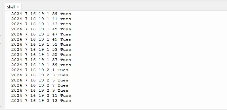
Open and run BM8563.py, the RTC time will be printed.
Example 5 I2C Device Sanner
Run the i2c_scan.py
from machine import Pin, I2C
import time

# Set up the I2C pins, using the default I2C pins for ESP32
sda = Pin(4)  # SDA pin
scl = Pin(5)  # SCL pin

# Initialize the I2C bus
i2c = I2C(0, scl=scl, sda=sda)

# Scan for devices on the I2C bus
print("Scanning I2C bus...")

# Iterate through the possible I2C address range
for addr in range(127):
    try:
        # Attempt to read a byte from the device at the current address
        i2c.readfrom(addr, 1)
        print("Found device at address:", hex(addr))
    except:
        # If an exception occurs, it means the device is not present at this address
        pass

print("Scan complete.")
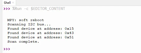
The I2C device will be printed.
Example 6 Control Vibration Motor
-
Add library
Add pi4ioe5v6408ztaex.py to the MicroPython device in the same way as in Example 2
# PI4IOE5V6408 I2C address PI4IOE5V6408_ADDR = 0x43 # Define register addresses using the 'const' function for clarity and to avoid magic numbers DEVICE_ID_AND_CONTROL = const(0x01) I_O_DIRECTION = const(0x03) OUTPUT_PORT = const(0x05) OUTPUT_HIGH_IMPEDANCE = const(0x07) INPUT_DEFAULT_STATE = const(0x09) PULL_UP_DOWN_ENABLE = const(0x0B) PULL_UP_DOWN_SELECT = const(0x0D) INPUT_STATUS = const(0x0F) INTERRUPT_MASK = const(0x11) INTERRUPT_STATUS = const(0x13) class PI4IOE5V6408: def __init__(self, i2c): # Initialize the I2C device and set up the I/O direction and output state self.i2c = i2c # Set all pins as outputs self.i2c.writeto_mem(PI4IOE5V6408_ADDR, I_O_DIRECTION, b'\xff') # Set all pins to output low by default (high impedance state) self.i2c.writeto_mem(PI4IOE5V6408_ADDR, OUTPUT_HIGH_IMPEDANCE, b'\x00') def write_pin(self, pin_number, value): # Read the current state of the output port rxdata = self.i2c.readfrom_mem(PI4IOE5V6408_ADDR, OUTPUT_PORT, 1) # Set the pin state based on the 'value' parameter if value: # Set the pin high new_state = rxdata[0] | (1 << pin_number) else: # Set the pin low new_state = rxdata[0] & ~(1 << pin_number) # Write the new state back to the output port self.i2c.writeto_mem(PI4IOE5V6408_ADDR, OUTPUT_PORT, new_state.to_bytes(1, 'big')) # Optionally read back the output state to verify the change rxdata = self.i2c.readfrom_mem(PI4IOE5V6408_ADDR, OUTPUT_PORT, 1) -
Open and run PI4IOE5V6408.py, the screen backlight and vibration motor will work for one second and then stop working.
Example 7 Initialize touch
-
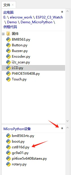
Add library
Add cst816d.py to the MicroPython device in the same way as in Example 2
from machine import Pin,I2C class Touch_CST816D(object): #Initialize the touch chip def __init__(self,address=0x15,mode=1,i2c_num=0,i2c_sda=4,i2c_scl=5,int_pin=0): self._bus = I2C(i2c_num,scl=Pin(i2c_scl),sda=Pin(i2c_sda)) #Initialize I2C self._address = address #Set slave address self.int=Pin(int_pin,Pin.IN, Pin.PULL_UP) bRet=self.WhoAmI() if bRet : print("Success:Detected CST816D.") Rev= self.Read_Revision() print("CST816D Revision = {}".format(Rev)) self.Stop_Sleep() else : print("Error: Not Detected CST816D.") return None self.Mode = mode self.Gestures="None" self.Flag = self.Flgh =self.l = 0 self.X_point = self.Y_point = 0 self.int.irq(handler=self.Int_Callback,trigger=Pin.IRQ_FALLING) def _read_byte(self,cmd): rec=self._bus.readfrom_mem(int(self._address),int(cmd),1) return rec[0] def _read_block(self, reg, length=1): rec=self._bus.readfrom_mem(int(self._address),int(reg),length) return rec def _write_byte(self,cmd,val): self._bus.writeto_mem(int(self._address),int(cmd),bytes([int(val)])) def WhoAmI(self): if (0xB6) != self._read_byte(0xA7): return False return True def Read_Revision(self): return self._read_byte(0xA9) #Stop sleeping def Stop_Sleep(self): self._write_byte(0xFE,0x01) #Set mode def Set_Mode(self,mode,callback_time=10,rest_time=5): # mode = 0 gestures mode # mode = 1 point mode # mode = 2 mixed mode if (mode == 1): self._write_byte(0xFA,0X41) elif (mode == 2) : self._write_byte(0xFA,0X71) else: self._write_byte(0xFA,0X11) self._write_byte(0xEC,0X01) #Get the coordinates of the touch def get_point(self): xy_point = self._read_block(0x03,4) x_point= ((xy_point[0]&0x0f)<<8)+xy_point[1] y_point= ((xy_point[2]&0x0f)<<8)+xy_point[3] self.X_point=x_point self.Y_point=y_point def Int_Callback(self,pin): if self.Mode == 0 : self.Gestures = self._read_byte(0x01) elif self.Mode == 1: self.Flag = 1 self.get_point() def Timer_callback(self,t): self.l += 1 if self.l > 100: self.l = 50 -
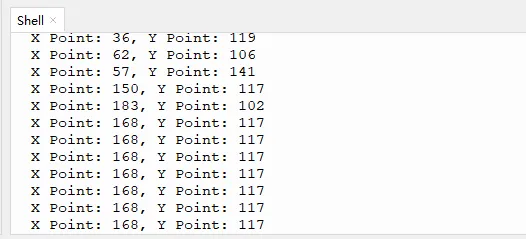
Open and run Touch.py.
from machine import Pin, I2C # Import the Pin and I2C classes from the machine module. from cst816d import Touch_CST816D # Import the Touch_CST816D class from the cst816d module. import time # Import the time module for delay functions. # Create an instance of the Touch_CST816D class, initializing in point mode (mode=1). Touch = Touch_CST816D(mode=1) # Set the mode attribute of the Touch object to 1, indicating point mode. Touch.Mode = 1 # Call the Set_Mode method to configure the touch chip in the specified mode. Touch.Set_Mode(Touch.Mode) # Main loop that keeps the program running. while True: # Call the get_point method to read the current touch point coordinates. Touch.get_point() # Print the X and Y coordinates of the touch point. print("X Point: {}, Y Point: {}".format(Touch.X_point, Touch.Y_point)) # Delay the loop for 100 milliseconds to reduce CPU usage and wait for the next reading. time.sleep_ms(100) # Use sleep_ms for a shorter delay. -
Touch the screen, the coordinates of the touched point will be printed.
Example 8 Initialize screen
-
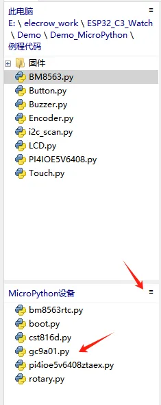
Add library
Add gc9a01.py to the MicroPython device in the same way as in Example 2
-
Open and run LCD.py
from machine import Pin,I2C from pi4ioe5v6408ztaex import PI4IOE5V6408 from gc9a01 import LCD_1inch28 import time # Initialize the I2C bus with the specified pins and frequency i2c = I2C(0, sda=Pin(4), scl=Pin(5), freq=400_000) # Create an instance of the PI4IOE5V6408 class with the I2C bus io_expander = PI4IOE5V6408(i2c) io_expander.write_pin(4, True) time.sleep(1) io_expander.write_pin(2, True) time.sleep(1) LCD = LCD_1inch28() LCD.text("Elecrow",90,120,LCD.blue) LCD.show() time.sleep(5) while True: LCD.fill(LCD.red) LCD.show() time.sleep(1) LCD.fill(LCD.green) LCD.show() time.sleep(1) LCD.fill(LCD.blue) LCD.show() time.sleep(1) -
There will be "Elecrow" shown on the screen, then the screen color will turn red, green, and blue in a cycle.
