Pico HMI 4.3-inch Arduino Tutorial
Overview
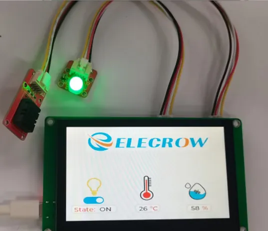
The example tutorial is an environmental monitoring project, demonstrate how to create a UI and use a DHT20 sensor to obtain the ambient temperature and humidity and display it on the screen; and how to control the LED on and off by the buttons on the screen.
In this tutorial, we will show you how to design the UI with SquareLine Studio, and show you how to upload the code with Arduino IDE.
Hardware Preparation
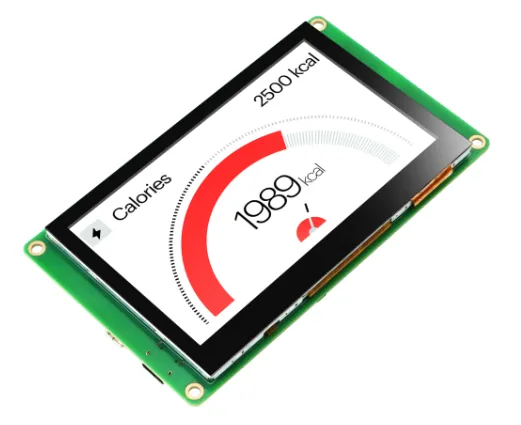
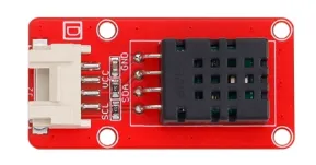
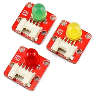
| CrowPanel PICO 4.3'' HMI | Crowtail-DHT20 | Crowtail-LED | USB-C Cable | 4 Pin Crowtail Cable |
|---|---|---|---|---|
 |  |  | 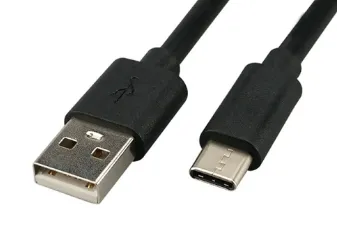 | 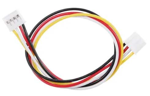 |
 | | | | |
Design UI file with SquareLine Studio
Get Started with SquareLine Studio
Please click the card below to learn how to download the SquareLine Studio, and how to export the demo UI file.

Design UI file with SquareLine Studio
Let's start learning how to create our own UI after getting an initial understanding of SquareLine Studio.
-
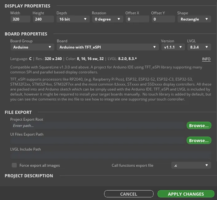
Open the SquareLine Studio and create a project. Select "Arduino"->"Arduino with TFT_eSPI".
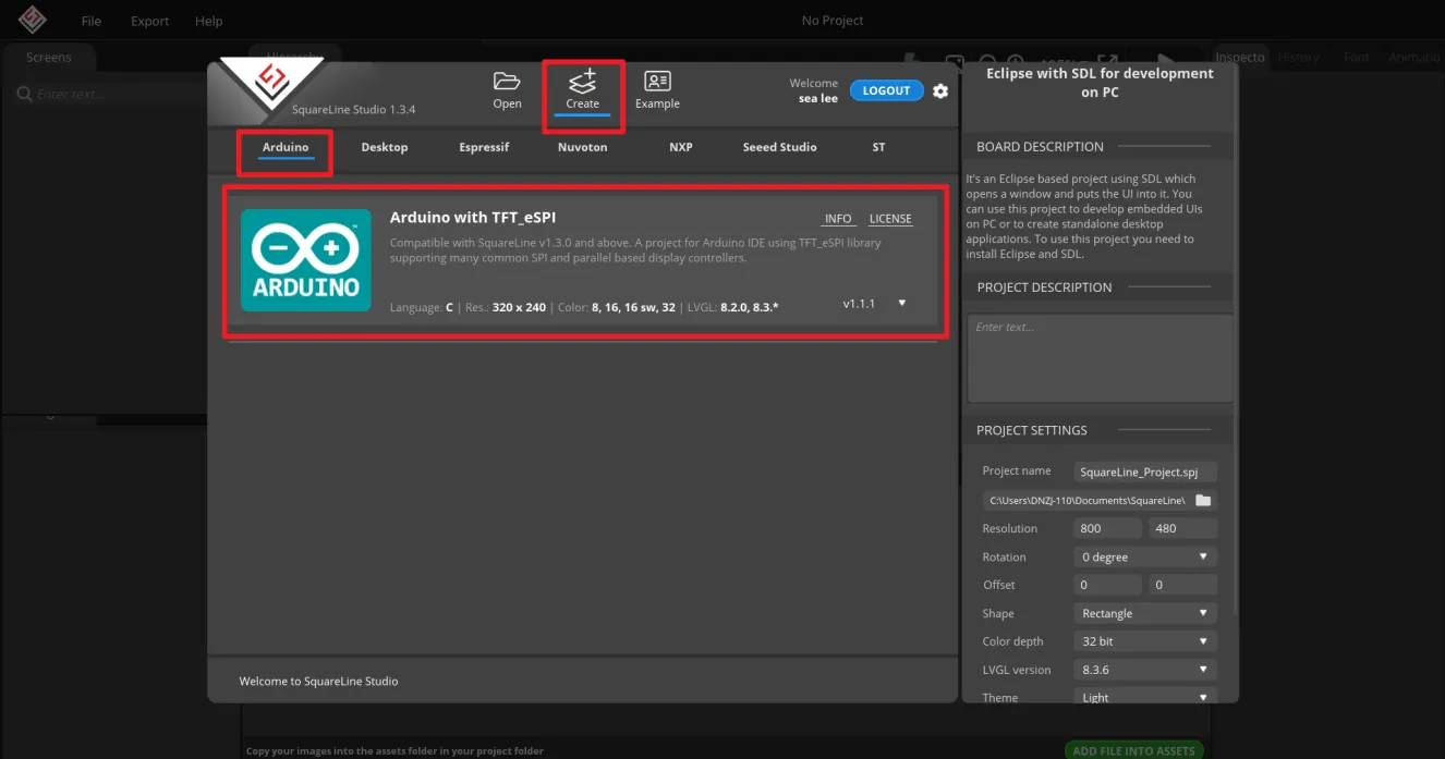
Note:
When select the Arduino framwork, there's only one option "Arduino with TFT_eSPI". By choosing this, the squareline studio will generate a template code suitable for the TFT_eSPI library. However, squareline studio not only supports the TFT_eSPI library, it supports a variety of libraries to suit different hardware and application needs. For example, Adafruit_GFX library, LovyanGFX etc.
After using SLS to generate UI code, we then use different graphics libraries according to different hardware and modify the corresponding code to display the content you design.
-
Set the name of the project, set the screen resolution to 320*240, set the color depth to 16bit, and keep other default settings. After setting, click CREATE to create the project.
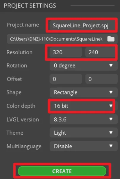
- 16-bit color depth: can represent 65,536 colors through RGB 5:6:5 sub-pixel representation, that is, each RGB channel occupies 5 bits and 1 bit (a total of 16 bits) to represent colors.
-
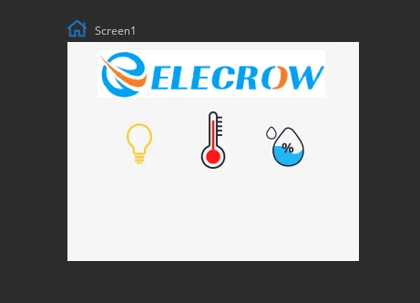
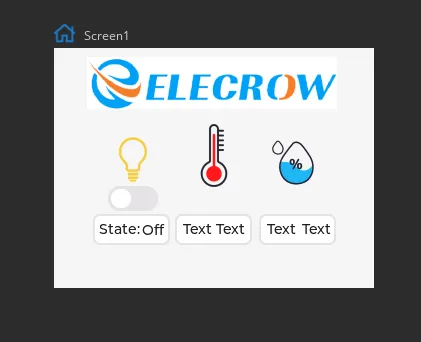
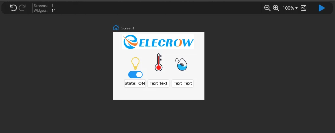
After creation, enter the following interface with a blank background.
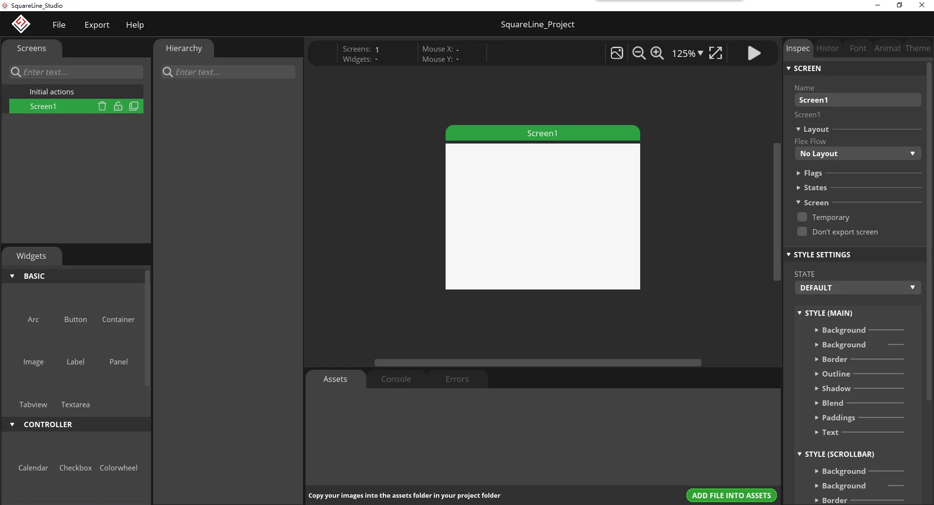
-
In the "Assets" area, click "ADD FILE TO ASSETS" to add custom images or icons.
Please click
 to download the custom images used in this tutorial.
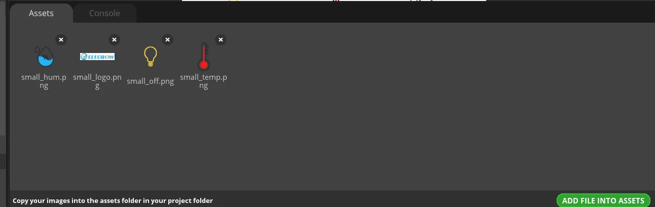
Note:
Images only support PNG format. The pixels of the image need to be smaller than the pixel size of the screen used in your project. The size of each image should not exceed 100k, preferably within 30k, to provide a smooth display effect.
-
Select "Image" to add icons.
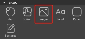
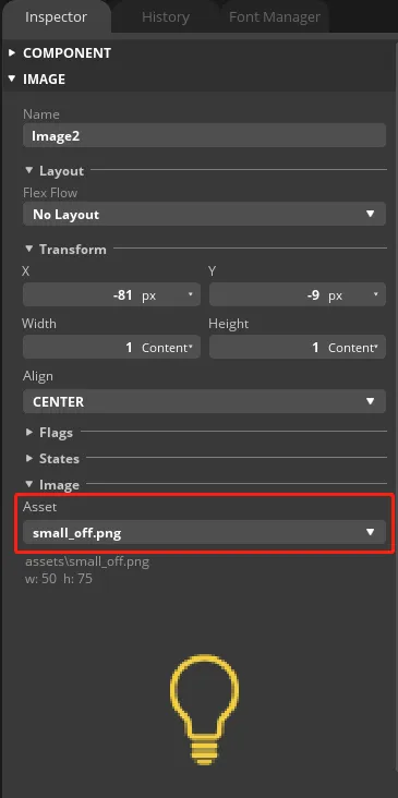
Repeat the above steps to add other icons.
-
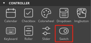
Find "CONTROLLER" and click "switch" , place the switch under small_off.webp
Then find "BASIC" and click "Panel", and add two "Label" at the "Panel".
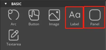
Note the hierarchy.

-
Selected the "Label", the contents of the label can be modified in the "Inspector". Modified as shown in the following picture.
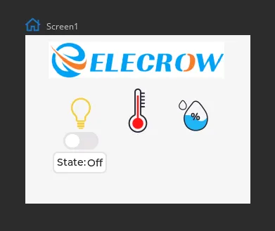
Please add a "Panel" and two "Label" for the remaining two icons.
-
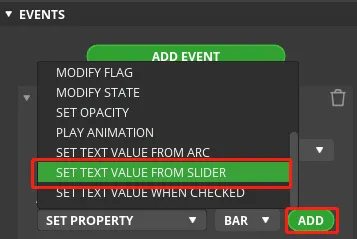
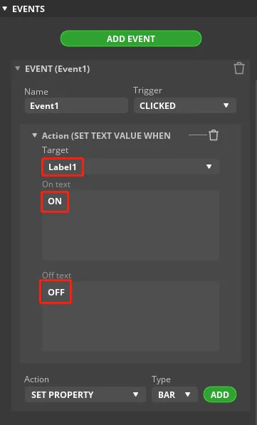
Select the "Switch" we built earlier, and add an event to "Switch". "Inspector"→"EVENTS"→"ADD EVENT"
-
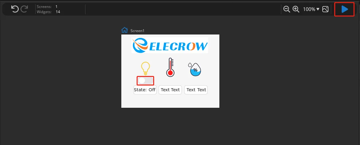
Click the Play button in the upper right corner to check whether the event is added successfully.
-
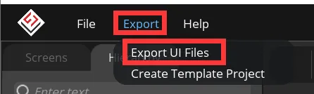
Export UI files.
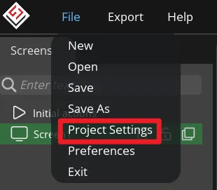
Click "File" -> "Project Settings" and make settings for the exported file.
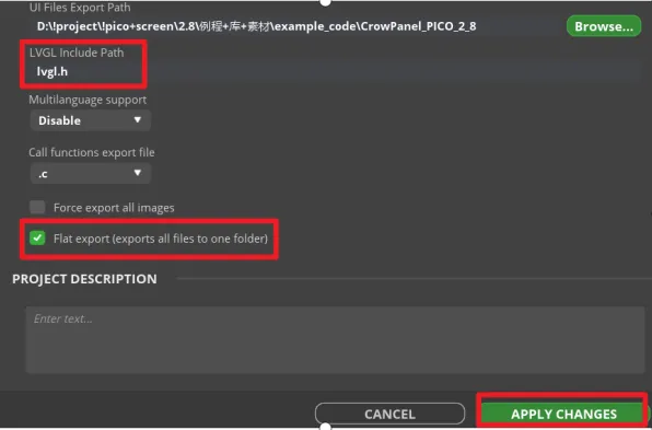
Set the export path of the file (set the path according to your own file).
Fill in lvgl.h in LVGL Include Path. Check "Flat export(exports all files to one folder )".
Then click "APPLY CHANGES".
Tips: After selecting the flat export, the output files will be in the same folder, so that the output code does not need to modify the path in the program. If not, the output files will be classified and placed in different folders. The compiler may not be able to recognize different paths, which will cause some trouble. In this case, the user needs to modify it manually, so it is recommended to select all files to be output to the same folder.
Export UI files. The exported files will be in the path we set earlier.
The following picture is the output UI file
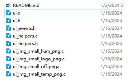
In order to be used with the main program, all UI files generated need to be placed in the same folder as the main program.
Please clickto download the main program(and the expert UI is included).
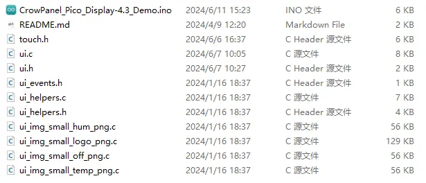
-
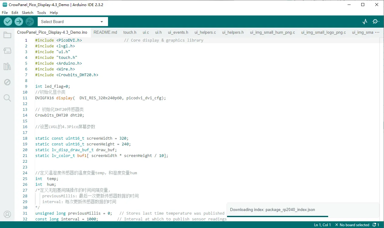
Open the main program. And all the UI file in the same folder will open too.
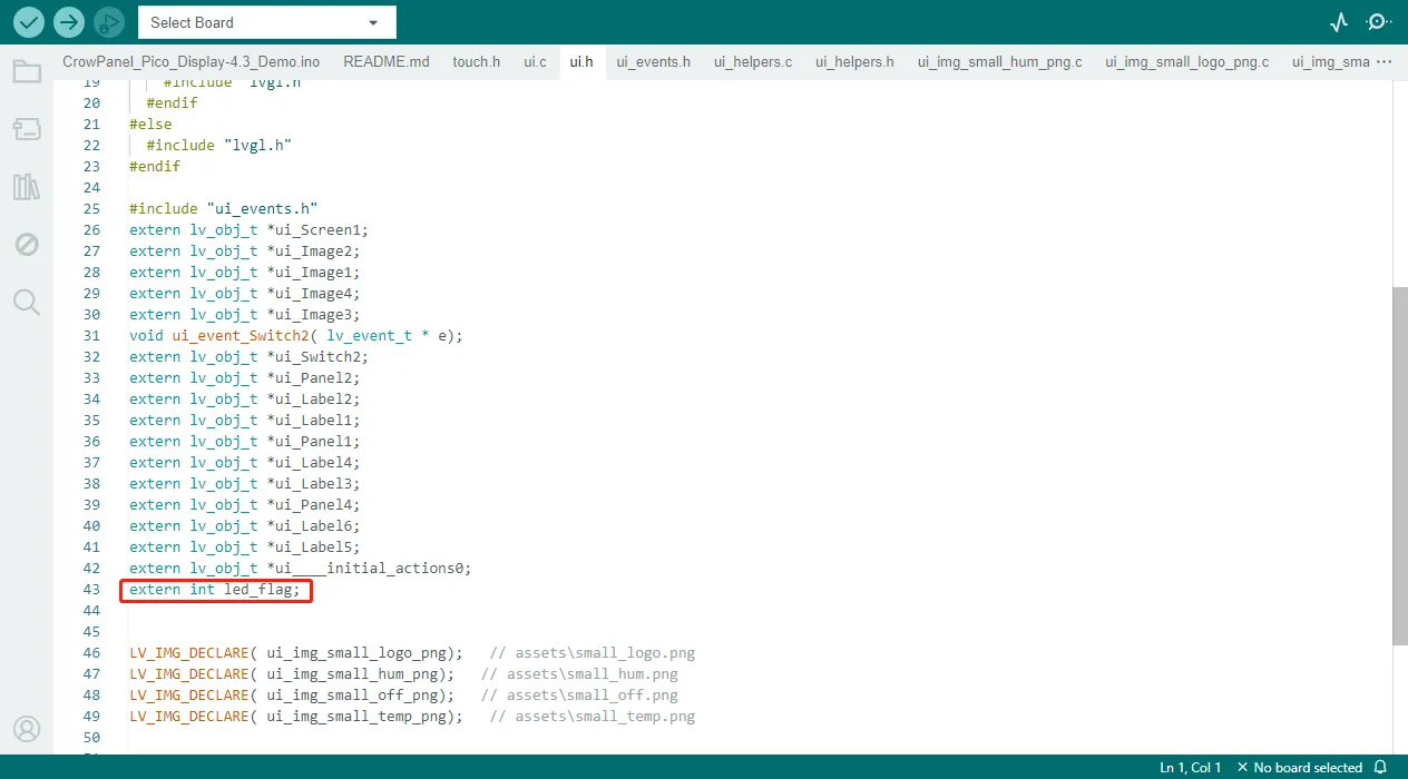
First, define a variable in the ui.h file to store the status of the LED. In the main program, the LED light is controlled to turn on and off by judging the status of this variable.
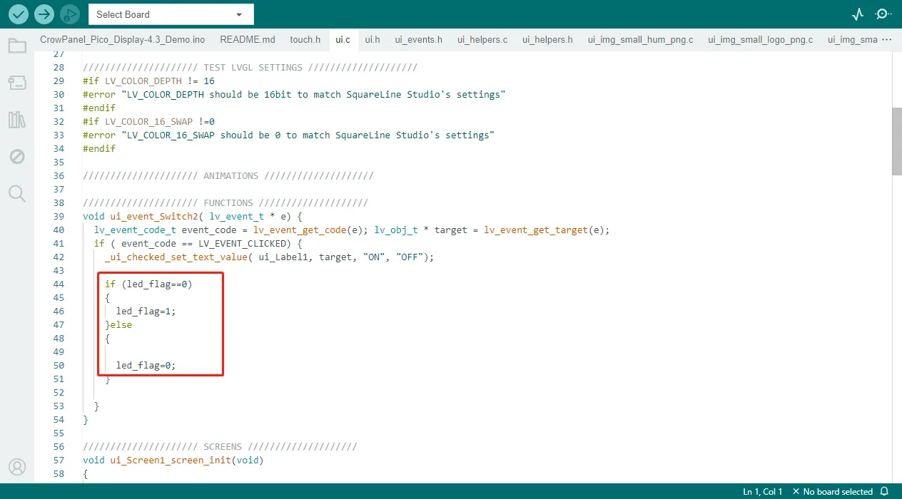
Then find "FUNCTION" in the ui. c file. Here is the corresponding code generated when we add events in SquareLine.
Next we're going to learn about the Arduino main program and learn how to upload the code to the board.
Build the Project with Arduino IDE
Get Started with Arduino IDE
Please click the card below to learn how to install Arduino IDE, and install RP2040 board in the Arduino IDE.

Add Libraries
In this project, we will use the following libraries:
#include <PicoDVI.h>
#include <lvgl.h>
#include "ui.h"
#include "touch.h"
#include <Arduino.h>
#include <Wire.h>
#include <Crowbits_DHT20.h>
#include <Arduino.h>: contains the Arduino core library, providing commonly used functions and data types.#include <lvgl.h>: is library for graphical interfaces, used for display control and drawing.- "ui.h": is a custom header file that contain UI-related functions or definitions.
#include <Wire.h>: here we use this library for I2C communication.- "DHT20.h": to read data from the DHT20 temperature and humidity sensor.
Please clickto download the libraries we modified.
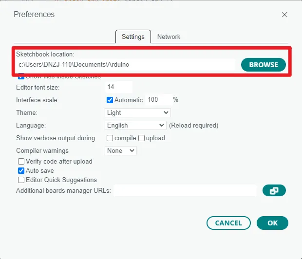
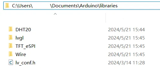
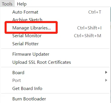
Then click "File" -> "Preferences" -> "Setting" to check the sketchbook location. Place the libraries downloaded to the sketchbook location.
Tips:
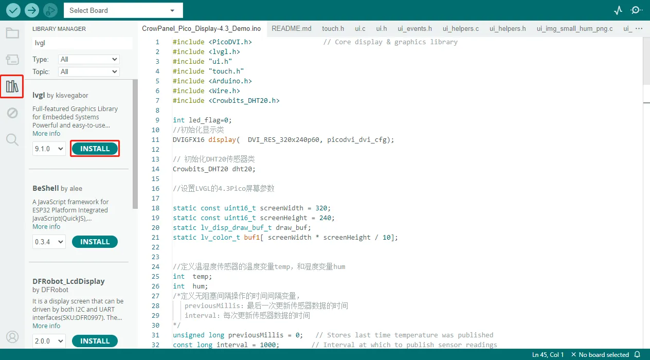
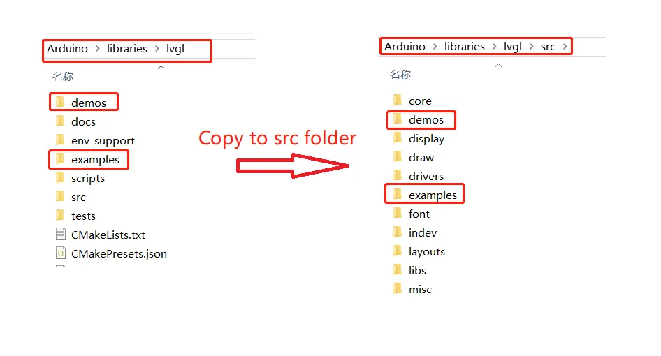
- If you install the lvgl libraries by Library Manager, you need to copy the demos folder and examples folder and paste them to src folder. And modify the lv_conf_template.h file and rename it to lv_conf.h, and place it in libraries folder.(Please refer to the library provided)
Code Explanation
Set Up Part
void setup()
{
      /*Sets the output mode of the TouchPin and ledPin
     TouchPin:INPUT
     ledPin:OUTPUT
  */
  pinMode(ledPin, OUTPUT);
  digitalWrite(ledPin, LOW);

  //Initialize the baud rate of the USB virtual serial port to 115200
  Serial.begin(115200); /*serial init */
      /*Due to the different pins of different boards, the SDA and SCL pins of the IIC need to be reset
     Wire.setSDA(2):Set SDA pin to 2
     Wire.setSCL(3):Set SCL pin to 3
  */
  Wire.setSDA(2);
  Wire.setSCL(3);
  //Initialize IIC
  Wire.begin();

  //Turn on the screen backlight
  pinMode(24, OUTPUT);
  digitalWrite(24, LOW); // Enable backlight
  //Initialize screen
  if (!display.begin()) {

  }
  //Set the rotation direction to 0
  display.setRotation(0);  // Takes effect on next drawing command
  //Fill the screen in black
  display.fillScreen(0x0000);

  delay(1000);

  //Initialize touch screen
  touch_init(screenWidth, screenHeight);
  //Initialize lvgl
  lv_init();
    /*Initializes the LCGL buffer
     draw_buf_t *draw_buf: A pointer to the initialized display buffer
     uint8_t *buf1: The address of the memory buffer
     lv_color_t *NULL1: The address of the optional second buffer
     screenWidth * screenHeight / 10: The size of the buffer, usually in bytes
  */
  lv_disp_draw_buf_init( &draw_buf, buf1, NULL, screenWidth * screenHeight / 10 );
  //Register LVGL to display callback functions
  /*Initialize the display*/
  static lv_disp_drv_t disp_drv;
  lv_disp_drv_init( &disp_drv );
  /*Change the following line to your display resolution*/
  disp_drv.hor_res = screenWidth;
  disp_drv.ver_res = screenHeight;
  disp_drv.flush_cb = my_disp_flush;
  disp_drv.draw_buf = &draw_buf;
  // disp_drv.full_refresh = 1;
  lv_disp_drv_register( &disp_drv );
  //Register the LVGL touch callback function
  /*Initialize the (dummy) input device driver*/
  static lv_indev_drv_t indev_drv;
  lv_indev_drv_init( &indev_drv );
  indev_drv.type = LV_INDEV_TYPE_POINTER;
  indev_drv.read_cb = my_touchpad_read;
  lv_indev_drv_register( &indev_drv );

  //Initialize the UI interface
  ui_init();        //LVGL UI init
  Serial.println( "Setup done" );
  delay(200);


}
Main Program Part
void loop()
{

  //According to the button status to determine whether to light
    if (led_flag == 1)
    {
      digitalWrite(ledPin, HIGH);
      lv_obj_add_state(ui_Switch2, LV_STATE_CHECKED);

    }
    else
    {
      digitalWrite(ledPin, LOW);
      lv_obj_clear_state(ui_Switch2, LV_STATE_CHECKED);
    }
//The LVGL timer task function is called to update the status of the UI
  lv_timer_handler();
  delay(10);
      //Get touch sensor data without blocking, if the interval is too short it will cause the program to stall

    unsigned long currentMillis = millis();
    if (currentMillis - previousMillis >= interval)
    {
      previousMillis = currentMillis;
      // Reading humidity data
      hum = (int)dht20.getHumidity();
      // Read temperature data
      temp = (int)dht20.getTemperature();
      Serial.print("hum:");
      Serial.println( hum);
      Serial.print("temp:");
      Serial.println( temp);
      /*Convert temperature and humidity values to update UI. itoa function parameters are described as follows:
       hum,temp:The value to be converted
       buffer_h,buffer_h:Stores the converted variable
       10:Stores the size of the converted variable
    */
      itoa(hum, buffer_h, 10);
      itoa(temp, buffer_t, 10);
      //Update the UI data
      lv_label_set_text(ui_Label3, buffer_t);
      lv_label_set_text(ui_Label5, buffer_h);
      //Check whether the temperature and humidity data is successfully read
      if (isnan(temp) || isnan(hum))
      {
        Serial.println(F("Failed to read from DHT20 sensor!"));
        return;
      }


    }
}
The Complete Code
#include <PicoDVI.h>                  // Core display & graphics library
#include <lvgl.h>
#include "ui.h"
#include "touch.h"
#include <Arduino.h>
#include <Wire.h>
#include <Crowbits_DHT20.h>

int led_flag=0;
//Initializes the display class
DVIGFX16 display(  DVI_RES_320x240p60, picodvi_dvi_cfg);

// Initializes the DHT20 sensor class
Crowbits_DHT20 dht20;

//Set the LVGL's 4.3inch Pico screen parameters

static const uint16_t screenWidth = 320;
static const uint16_t screenHeight = 240;
static lv_disp_draw_buf_t draw_buf;
static lv_color_t buf1[ screenWidth * screenHeight / 10];


//Define the temperature variable temp and the humidity variable hum for the temperature and humidity sensor
int  temp;
int  hum;
/*Defines a time interval variable for a non-blocking interval operation
   previousMillis:the sensor data was last updated
   interval:Everytime the sensor data is updated
*/
unsigned long previousMillis = 0;   // Stores last time temperature was published
const long interval = 1000;        // Interval at which to publish sensor readings

/*Define the variables that store the converted temperature and humidity data
   buffer_t[10]:A variable that stores the converted temperature data
   buffer_h[10]:A variable that stores the converted humidity data
*/
char buffer_t[10];
char buffer_h[10];

/*Define pins for touch sensors and LED lights
   ledPin:LED pin
*/
const int ledPin = 28;

/*LVGL displays the callback function
   Parameter immutable
*/
/* Display flushing */
void my_disp_flush( lv_disp_drv_t *disp, const lv_area_t *area, lv_color_t *color_p )
{
  uint32_t w = ( area->x2 - area->x1 + 1 );
  uint32_t h = ( area->y2 - area->y1 + 1 );
  display.drawRGBBitmap(area->x1, area->y1, (uint16_t *)&color_p->full, w, h);
  lv_disp_flush_ready( disp );
}
/*LVGL touches the callback function
   Parameter immutable
*/
void my_touchpad_read(lv_indev_drv_t *indev_driver, lv_indev_data_t *data)
{
  if (touch_has_signal()) {
    if (touch_touched()) {
      data->state = LV_INDEV_STATE_PRESSED;

      /*Set the coordinates*/
      data->point.x = touch_last_x;
      data->point.y = touch_last_y;
      // Serial2.print( "Data x " );
      // Serial2.println( data->point.x );
      // Serial2.print( "Data y " );
      // Serial2.println( data->point.y );
    } else if (touch_released()) {
      data->state = LV_INDEV_STATE_RELEASED;
    }
  } else {
    data->state = LV_INDEV_STATE_RELEASED;
  }
}
void setup()
{
      /*Sets the output mode of the TouchPin and ledPin
     TouchPin:INPUT
     ledPin:OUTPUT
  */
  pinMode(ledPin, OUTPUT);
  digitalWrite(ledPin, LOW);

  //Initialize the baud rate of the USB virtual serial port to 115200
  Serial.begin(115200); /*serial init */
      /*Due to the different pins of different boards, the SDA and SCL pins of the IIC need to be reset
     Wire.setSDA(2):Set SDA pin to 2
     Wire.setSCL(3):Set SCL pin to 3
  */
  Wire.setSDA(2);
  Wire.setSCL(3);
  //Initialize IIC
  Wire.begin();

  //Turn on the screen backlight
  pinMode(24, OUTPUT);
  digitalWrite(24, LOW); // Enable backlight
  //Initialize screen
  if (!display.begin()) {

  }
  //Set the rotation direction to 0
  display.setRotation(0);  // Takes effect on next drawing command
  //Fill the screen in black
  display.fillScreen(0x0000);

  delay(1000);

  //Initialize touch screen
  touch_init(screenWidth, screenHeight);
  //Initialize lvgl
  lv_init();
    /*Initializes the LCGL buffer
     draw_buf_t *draw_buf: A pointer to the initialized display buffer
     uint8_t *buf1: The address of the memory buffer
     lv_color_t *NULL1: The address of the optional second buffer
     screenWidth * screenHeight / 10: The size of the buffer, usually in bytes
  */
  lv_disp_draw_buf_init( &draw_buf, buf1, NULL, screenWidth * screenHeight / 10 );
  //Register LVGL to display callback functions
  /*Initialize the display*/
  static lv_disp_drv_t disp_drv;
  lv_disp_drv_init( &disp_drv );
  /*Change the following line to your display resolution*/
  disp_drv.hor_res = screenWidth;
  disp_drv.ver_res = screenHeight;
  disp_drv.flush_cb = my_disp_flush;
  disp_drv.draw_buf = &draw_buf;
  // disp_drv.full_refresh = 1;
  lv_disp_drv_register( &disp_drv );
  //Register the LVGL touch callback function
  /*Initialize the (dummy) input device driver*/
  static lv_indev_drv_t indev_drv;
  lv_indev_drv_init( &indev_drv );
  indev_drv.type = LV_INDEV_TYPE_POINTER;
  indev_drv.read_cb = my_touchpad_read;
  lv_indev_drv_register( &indev_drv );

  //Initialize the UI interface
  ui_init();        //LVGL UI init
  Serial.println( "Setup done" );
  delay(200);


}


void loop()
{

  //According to the button status to determine whether to light
    if (led_flag == 1)
    {
      digitalWrite(ledPin, HIGH);
      lv_obj_add_state(ui_Switch2, LV_STATE_CHECKED);

    }
    else
    {
      digitalWrite(ledPin, LOW);
      lv_obj_clear_state(ui_Switch2, LV_STATE_CHECKED);
    }
//The LVGL timer task function is called to update the status of the UI
  lv_timer_handler();
  delay(10);
      //Get touch sensor data without blocking, if the interval is too short it will cause the program to stall

    unsigned long currentMillis = millis();
    if (currentMillis - previousMillis >= interval)
    {
      previousMillis = currentMillis;
      // Reading humidity data
      hum = (int)dht20.getHumidity();
      // Read temperature data
      temp = (int)dht20.getTemperature();
      Serial.print("hum:");
      Serial.println( hum);
      Serial.print("temp:");
      Serial.println( temp);
      /*Convert temperature and humidity values to update UI. itoa function parameters are described as follows:
       hum,temp:The value to be converted
       buffer_h,buffer_h:Stores the converted variable
       10:Stores the size of the converted variable
    */
      itoa(hum, buffer_h, 10);
      itoa(temp, buffer_t, 10);
      //Update the UI data
      lv_label_set_text(ui_Label3, buffer_t);
      lv_label_set_text(ui_Label5, buffer_h);
      //Check whether the temperature and humidity data is successfully read
      if (isnan(temp) || isnan(hum))
      {
        Serial.println(F("Failed to read from DHT20 sensor!"));
        return;
      }


    }
}
Upload the Code
-
After completing the installation of the RP2040 board according to "Get Started with Arduino IDE" and the installation of the library according to "Add Libraries", open the program and connect the PICO HMI 3.5-inch to the computer via a USB-C cable.
-
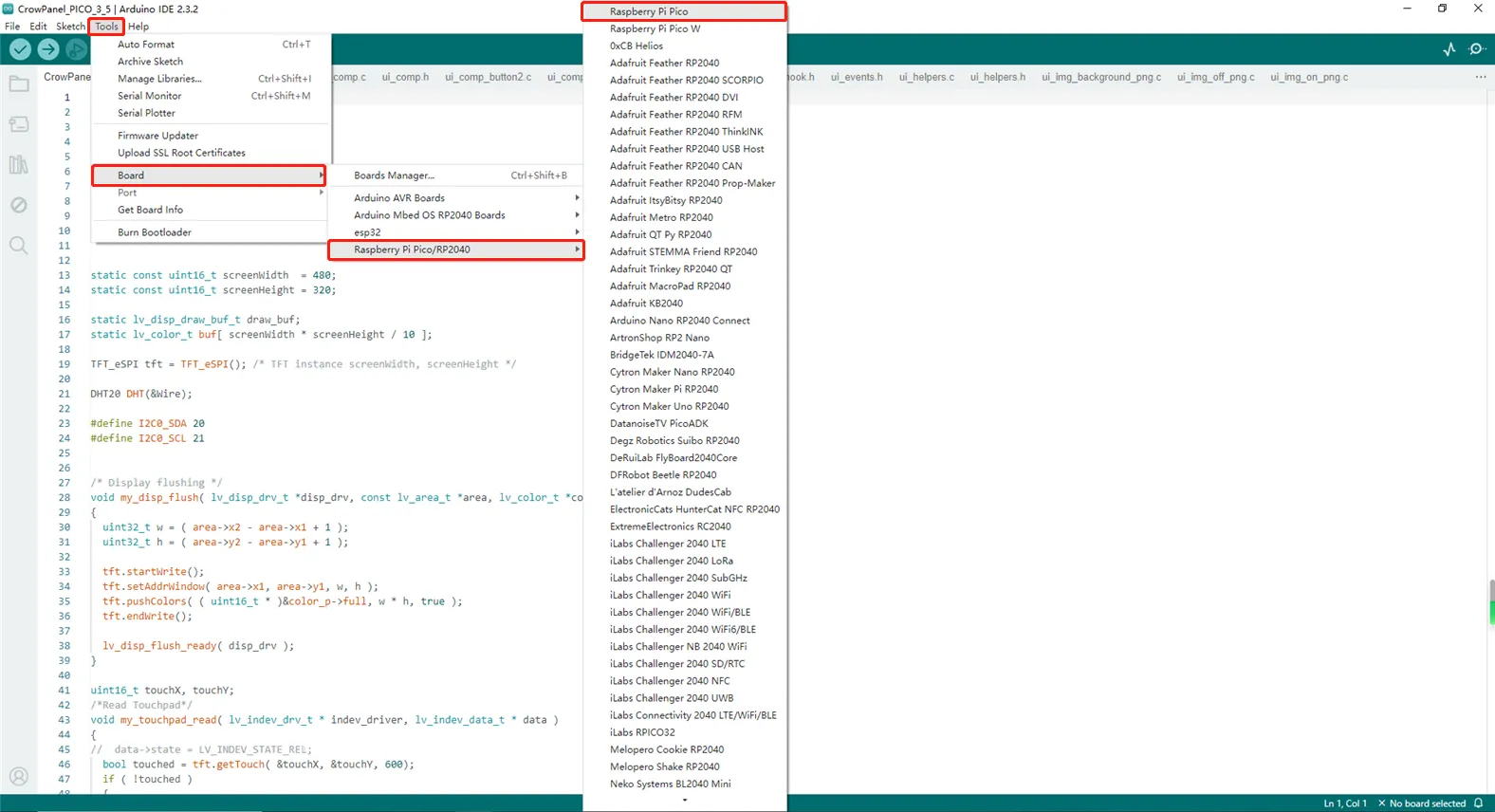
Select Board: click "Tools" -> "Board" -> "Raspberry Pi Pico/RP2040" and select "Raspberry Pi Pico"
-
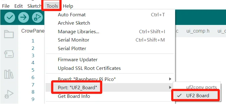
Select Port: Please hold the BOOT button and press the RESET button first, and the PICO HMI board will turn into a U disk. Then click "Tools" -> "Port" and select UF2...(Note: you need to press the button every time you need to connect the board with computer through serial communication.)
-
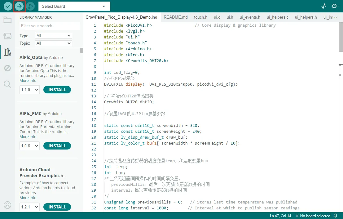
Upload the code
-
After the program is successfully uploaded, connect the DHT20 sensor to the IIC port and the LED to GPIO_D.
Click the Switch. When the State is ON, the LED is on. When the State is OFF, the LED is off. Temperature and humidity values are monitored in real time.
Example Demo of PICO HMI Function
Example1: ADC Module
Connect ADC module to ADC interface of development board. The detected ADC pin voltage value will output to the serial port. Note:"Tools"→ "Board" need to select Raspberry Pi Pico W
void setup() {
  // put your setup code here, to run once:
  Serial.begin(115200);

}

void loop() {
  // put your main code here, to run repeatedly:
//  int sensorValue =  analogRead(28);
  int sensorValue1 =  analogRead(27);
  Serial.print("sensorValue1:");
  Serial.println(sensorValue1);
  delay(1000);
}
Example2: Buzzer
Use a buzzer to play a piece of music on a loop.
 #define NOTE_D0 -1
 #define NOTE_DL1 261
 #define NOTE_DL2 293
 #define NOTE_DL3 311
 #define NOTE_DL4 349
 #define NOTE_DL5 391
 #define NOTE_DL6 440
 #define NOTE_DL7 493

 #define NOTE_D1 523
 #define NOTE_D2 587
 #define NOTE_D3 659
 #define NOTE_D4 698
 #define NOTE_D5 783
 #define NOTE_D6 880
 #define NOTE_D7 987

 #define NOTE_DH1 1046
 #define NOTE_DH2 1174
 #define NOTE_DH3 1318
 #define NOTE_DH4 1396
 #define NOTE_DH5 1567
 #define NOTE_DH6 1760
 #define NOTE_DH7 1975

 #define WHOLE 1
 #define HALF 0.5
 #define QUARTER 0.25
 #define EIGHTH 0.25
 #define SIXTEENTH 0.625

 int tune[] =
 {
   NOTE_DH1, NOTE_D6, NOTE_D5, NOTE_D6, NOTE_D0,
   NOTE_DH1, NOTE_D6, NOTE_D5, NOTE_DH1, NOTE_D6, NOTE_D0, NOTE_D6,
   NOTE_D6, NOTE_D6, NOTE_D5, NOTE_D6, NOTE_D0, NOTE_D6,
   NOTE_DH1, NOTE_D6, NOTE_D5, NOTE_DH1, NOTE_D6, NOTE_D0,

   NOTE_D1, NOTE_D1, NOTE_D3,
   NOTE_D1, NOTE_D1, NOTE_D3, NOTE_D0,
   NOTE_D6, NOTE_D6, NOTE_D6, NOTE_D5, NOTE_D6,
   NOTE_D5, NOTE_D1, NOTE_D3, NOTE_D0,
   NOTE_DH1, NOTE_D6, NOTE_D6, NOTE_D5, NOTE_D6,
   NOTE_D5, NOTE_D1, NOTE_D2, NOTE_D0,
   NOTE_D7, NOTE_D7, NOTE_D5, NOTE_D3,
   NOTE_D5,
   NOTE_DH1, NOTE_D0, NOTE_D6, NOTE_D6, NOTE_D5, NOTE_D5, NOTE_D6, NOTE_D6,
   NOTE_D0, NOTE_D5, NOTE_D1, NOTE_D3, NOTE_D0,
   NOTE_DH1, NOTE_D0, NOTE_D6, NOTE_D6, NOTE_D5, NOTE_D5, NOTE_D6, NOTE_D6,
   NOTE_D0, NOTE_D5, NOTE_D1, NOTE_D2, NOTE_D0,
   NOTE_D3, NOTE_D3, NOTE_D1, NOTE_DL6,
   NOTE_D1,
   NOTE_D3, NOTE_D5, NOTE_D6, NOTE_D6,
   NOTE_D3, NOTE_D5, NOTE_D6, NOTE_D6,
   NOTE_DH1, NOTE_D0, NOTE_D7, NOTE_D5,
   NOTE_D6,
 };

 float duration[] =
 {
   1, 1, 0.5, 0.5, 1,
   0.5, 0.5, 0.5, 0.5, 1, 0.5, 0.5,
   0.5, 1, 0.5, 1, 0.5, 0.5,
   0.5, 0.5, 0.5, 0.5, 1, 1,

   1, 1, 1 + 1,
   0.5, 1, 1 + 0.5, 1,
   1, 1, 0.5, 0.5, 1,
   0.5, 1, 1 + 0.5, 1,
   0.5, 0.5, 0.5, 0.5, 1 + 1,
   0.5, 1, 1 + 0.5, 1,
   1 + 1, 0.5, 0.5, 1,
   1 + 1 + 1 + 1,
   0.5, 0.5, 0.5 + 0.25, 0.25, 0.5 + 0.25, 0.25, 0.5 + 0.25, 0.25,
   0.5, 1, 0.5, 1, 1,
   0.5, 0.5, 0.5 + 0.25, 0.25, 0.5 + 0.25, 0.25, 0.5 + 0.25, 0.25,
   0.5, 1, 0.5, 1, 1,
   1 + 1, 0.5, 0.5, 1,
   1 + 1 + 1 + 1,
   0.5, 1, 0.5, 1 + 1,
   0.5, 1, 0.5, 1 + 1,
   1 + 1, 0.5, 0.5, 1,
   1 + 1 + 1 + 1
 };
  int length;
 int tonePin = 19;

 void setup()
 {
   pinMode(tonePin, OUTPUT);
   length = sizeof(tune) / sizeof(tune[0]);
 }
 void loop()
 {
   for (int x = 0; x < length; x++)
   {
     tone(tonePin, tune[x]);
     delay(400 * duration[x]);
     noTone(tonePin);
   }
   delay(5000);
 }
Example3: BW16 Communication
Sending AT instructions via serial port uses the function of the BW16 module
void setup() {
  // put your setup code here, to run once:
//  pinMode(25, OUTPUT);
//  digitalWrite(25, HIGH);   // turn the LED on (HIGH is the voltage level)
//  delay(1000);
  Serial.begin(115200);
  Serial2.setRX(5);
  Serial2.setTX(4);
  Serial2.begin(115200);
}

void loop() {
  if (Serial.available())
  {
    Serial2.write(Serial.read());
  }

  if (Serial2.available())
  {
    Serial.write(Serial2.read());
  }
}
Example4: Connect LED
Connect the LED to GPIO_D. The pins available for testing are 0,1,2,3,6,7,16,17,22,26,27,29. Achieve LED on and off.
#define GPIO0 0
#define GPIO1 1
#define GPIO2 2
#define GPIO3 3
#define GPIO4 6
#define GPIO5 7
#define GPIO6 16
#define GPIO7 17
#define GPIO8 22
#define GPIO9 26
#define GPIO10 27
#define GPIO11 29

void setup() {
  // put your setup code here, to run once:
  pinMode(GPIO0, OUTPUT);
  pinMode(GPIO1, OUTPUT);
  pinMode(GPIO2, OUTPUT);
  pinMode(GPIO3, OUTPUT);
  pinMode(GPIO4, OUTPUT);
  pinMode(GPIO5, OUTPUT);
  pinMode(GPIO6, OUTPUT);
  pinMode(GPIO7, OUTPUT);
  pinMode(GPIO8, OUTPUT);
  pinMode(GPIO9, OUTPUT);
  pinMode(GPIO10, OUTPUT);
  pinMode(GPIO11, OUTPUT);
}

void loop() {
  // put your main code here, to run repeatedly:
  digitalWrite(GPIO0, HIGH);
  digitalWrite(GPIO1, HIGH);
  digitalWrite(GPIO2, HIGH);
  digitalWrite(GPIO3, HIGH);
  digitalWrite(GPIO4, HIGH);
  digitalWrite(GPIO5, HIGH);
  digitalWrite(GPIO6, HIGH);
  digitalWrite(GPIO7, HIGH);
  digitalWrite(GPIO8, HIGH);
  digitalWrite(GPIO9, HIGH);
  digitalWrite(GPIO10, HIGH);
  digitalWrite(GPIO11, HIGH);
  delay(1000);
  digitalWrite(GPIO0, LOW);
  digitalWrite(GPIO1, LOW);
  digitalWrite(GPIO2, LOW);
  digitalWrite(GPIO3, LOW);
  digitalWrite(GPIO4, LOW);
  digitalWrite(GPIO5, LOW);
  digitalWrite(GPIO6, LOW);
  digitalWrite(GPIO7, LOW);
  digitalWrite(GPIO8, LOW);
  digitalWrite(GPIO9, LOW);
  digitalWrite(GPIO10, LOW);
  digitalWrite(GPIO11, LOW);
  delay(1000);
}
Example5: Test I2C
Connect the DHT20 temperature and humidity sensor to the I2C. Read data from the DHT20 temperature and humidity sensor and send the data to the serial port. Note:"Tools"→ "Board" need to select Adafruit Feather RP2040 DVI
//
//    FILE: DHT20_test_rp2040.ino
//  AUTHOR: Rob Tillaart
// PURPOSE: Demo for DHT20 I2C humidity & temperature sensor
//     URL: https://github.com/RobTillaart/DHT20
//
//  Always check datasheet - front view
//
//          +--------------+
//  VDD ----| 1            |
//  SDA ----| 2    DHT20   |
//  GND ----| 3            |
//  SCL ----| 4            |
//          +--------------+


#include <Crowbits_DHT20.h>
#include <Wire.h>

Crowbits_DHT20 DHT;  //  or use 2nd I2C interface &Wire1


void setup()
{
  Serial.begin(115200);


  Wire.setSDA(2);  //  select your pin numbers here
  Wire.setSCL(3);  //  select your pin numbers here
  Wire.begin();

  delay(2000);


}


void loop()
{


  //  DISPLAY DATA, sensor has only one decimal.
  Serial.print("Humidity: ");
  Serial.print((int)DHT.getHumidity(), 1);
  Serial.print(",\t");
  Serial.print("Temperature: ");
  Serial.println((int)DHT.getTemperature(), 1);

  delay(2000);
}


//  -- END OF FILE --
Example6: Use PWM to control the LED on and off
Connect the LED to the GPIO_D on pin 22. After compiling the program, it will achieve the effect of breathing light.
#define PWM_PIN 22

void setup ()
{
  pinMode(PWM_PIN,OUTPUT);
}

void loop()
{

  for (int brightness=0; brightness<=255;brightness++)
  {
    analogWrite(PWM_PIN,brightness);
    delay(8);
  }

  for (int brightness=255; brightness>=0;brightness--)
  {
    analogWrite(PWM_PIN,brightness);
    delay(8);
  }
  delay(800);
}
Example7: Use SD card
Read the SD card information
/*
  SD card read/write

  This example shows how to read and write data to and from an SD card file
  The circuit:
   SD card attached to SPI bus as follows:
   ** MISO - pin 4
   ** MOSI - pin 7
   ** CS   - pin 5
   ** SCK  - pin 6

  created   Nov 2010
  by David A. Mellis
  modified 9 Apr 2012
  by Tom Igoe

  This example code is in the public domain.

*/

// This are GP pins for SPI0 on the Raspberry Pi Pico board, and connect
// to different *board* level pinouts.  Check the PCB while wiring.
// Only certain pins can be used by the SPI hardware, so if you change
// these be sure they are legal or the program will crash.
// See: https://datasheets.raspberrypi.com/picow/PicoW-A4-Pinout.pdf
const int _MISO = 16;
const int _MOSI = 7;
const int _CS = 17;
const int _SCK = 6;

#include <SPI.h>
#include <SD.h>

File myFile;

void setup() {
  // Open Serial1 communications and wait for port to open:
//  Serial.setRX(1);
//  Serial.setTX(0);
  Serial.begin(115200);
  //delay(1000);
  Serial.println("\nInitializing SD card...");
//  SD_test();
}

void loop() {
  delay(100);
  bool sdInitialized = false;
  // Ensure the SPI pinout the SD card is connected to is configured properly
  // Select the correct SPI based on _MISO pin for the RP2040
  if (_MISO == 0 || _MISO == 4 || _MISO == 16) {
    SPI.setRX(_MISO);
    SPI.setTX(_MOSI);
    SPI.setSCK(_SCK);

    sdInitialized = SD.begin(_CS);
  } else if (_MISO == 8 || _MISO == 12) {
    SPI1.setRX(_MISO);
    SPI1.setTX(_MOSI);
    SPI1.setSCK(_SCK);
    sdInitialized = SD.begin(_CS, SPI1);
  } else {
    Serial.println(F("ERROR: Unknown SPI Configuration"));
    return;
  }

  // nothing happens after setup
  if (!sdInitialized) {
    Serial.println("initialization failed. Things to check:");
    Serial.println("* is a card inserted?");
    Serial.println("* is your wiring correct?");
    Serial.println("* did you change the chipSelect pin to match your shield or module?");
    return;
  } else {
    Serial.println("Wiring is correct and a card is present.");
  }
  // 0 - SD V1, 1 - SD V2, or 3 - SDHC/SDXC
  // print the type of card
  Serial.println();
  Serial.print("Card type:         ");
  switch (SD.type()) {
    case 0:
      Serial.println("SD1");
      break;
    case 1:
      Serial.println("SD2");
      break;
    case 3:
      Serial.println("SDHC/SDXC");
      break;
    default:
      Serial.println("Unknown");
  }

  Serial.print("Cluster size:          ");
  Serial.println(SD.clusterSize());
  Serial.print("Blocks x Cluster:  ");
  Serial.println(SD.blocksPerCluster());
  Serial.print("Blocks size:  ");
  Serial.println(SD.blockSize());

  Serial.print("Total Blocks:      ");
  Serial.println(SD.totalBlocks());
  Serial.println();

  Serial.print("Total Cluster:      ");
  Serial.println(SD.totalClusters());
  Serial.println();

  // print the type and size of the first FAT-type volume
  uint32_t volumesize;
  Serial.print("Volume type is:    FAT");
  Serial.println(SD.fatType(), DEC);

  volumesize = SD.totalClusters();
  volumesize *= SD.clusterSize();
  volumesize /= 1000;
  Serial.print("Volume size (Kb):  ");
  Serial.println(volumesize);
  Serial.print("Volume size (Mb):  ");
  volumesize /= 1024;
  Serial.println(volumesize);
  Serial.print("Volume size (Gb):  ");
  Serial.println((float)volumesize / 1024.0);

  Serial.print("Card size:  ");
  Serial.println((float)SD.size() / 1000);
  delay(5000);
}
Example8: Touch
Read the touch screen coordinates and send them to the serial port. Note:"Tools"→ "Board" need to select Adafruit Feather RP2040 DVI
#include "touch.h"

void setup() {
  Serial.begin(115200);

  touch_init();
}

void loop() {
  while (touch_has_signal())
  {
    if (touch_touched())
    {
      Serial.print( "Data x :" );
      Serial.print( touch_last_x );
      Serial.print( "  Data y :" );
      Serial.println( touch_last_y );
      break;
    }
  }
  delay(10);
}
Example9: UART0 communication
Connect one end to UART0 and the other end to a PC. Send and receive messages.
#define  Serial1_RX 1
#define  Serial1_TX 0

char BW16_temp;
char BW16_buf[128];
int8_t bufindex;
int flag =  1;
void UART1_Init()
{
  Serial1.setRX(Serial1_RX);
  Serial1.setTX(Serial1_TX);
  Serial1.begin(115200);
  delay(1000);
}

void setup() {
  // put your setup code here, to run once:
  //  Serial.begin(115200);
  UART1_Init();
//  pinMode(25, OUTPUT);
}

void loop() {
  // put your main code here, to run repeatedly:
  UART1_test();
  //  Serial1.println("Hello");
  //  delay(1000);
  //  if (flag == 1)
  //  {
  //    digitalWrite(25, HIGH);
  //    flag = 0;
  //  }
  //  else
  //  {
  //    digitalWrite(25, LOW);
  //    flag = 1;
  //  }
  //  delay(1000);
}


void UART1_test()
{
  while (Serial.available())
  {
    BW16_temp = Serial.read();
    //Serial.print(BW16_temp);
    BW16_buf[bufindex++] = BW16_temp;
    Serial1.write(BW16_temp);
  }
  if (BW16_buf[0] == 'I' && BW16_buf[1] == 'I')
  {
    //    Close_Flag = 0;
    memset(BW16_buf, 0, 128);
    bufindex = 0;
  }
  else
  {
    memset(BW16_buf, 0, 128);
    bufindex = 0;
  }
  while (Serial1.available())
  {
    Serial.write(Serial1.read());
  }
}