ESP32 HMI 5.0-inch MicroPython Tutorial
Overview
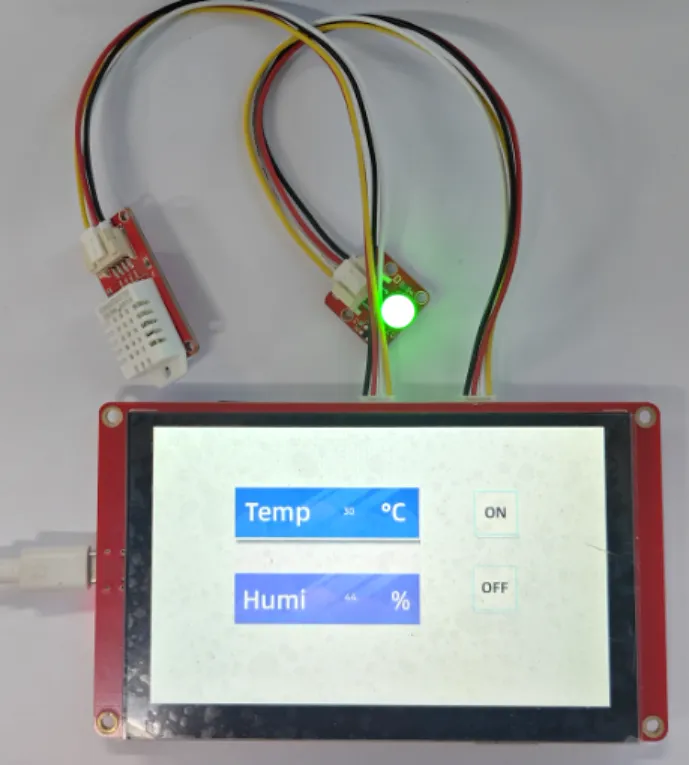
he example tutorial is an environmental monitoring project, demonstrate how to create a UI and use a sensor to obtain the environment temperature and humidity and display it on the screen; and how to control the LED on and off by the buttons on the screen.
In this tutorial, we will show you how to design the UI with SquareLine Studio, and show you how to upload the code with Thonny IDE.
Hardware Preparation
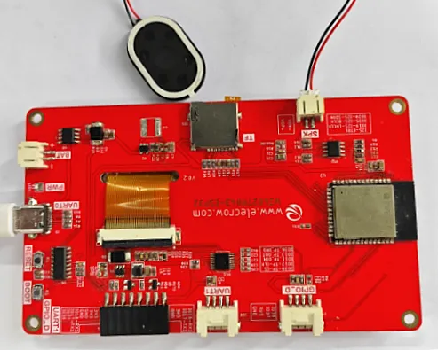
| CrowPanel ESP32 5.0'' HMI | Crowtail-AM2302 | Crowtail-LED | Crowtail Cable |
|---|---|---|---|
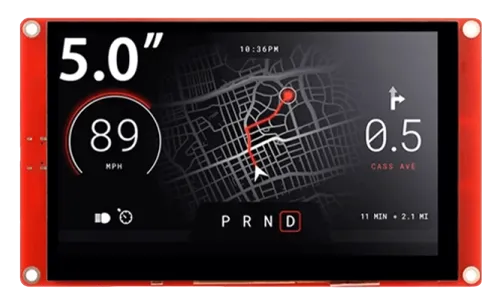 | 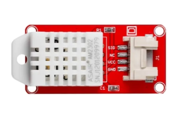 | 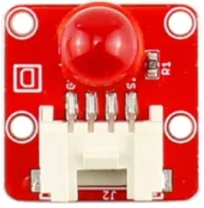 | 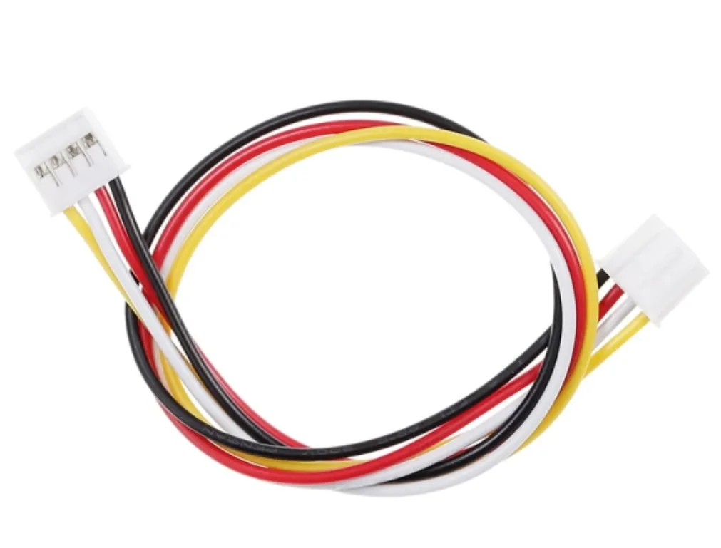 |
 | | | |
Design UI file with SquareLine Studio
Get Started with SquareLine Studio
Please click the card below to learn how to download the SquareLine Studio, and how to export the demo UI file.

Design UI file with SquareLine Studio
Let's start learning how to create our own UI after getting an initial understanding of SquareLine Studio.
-
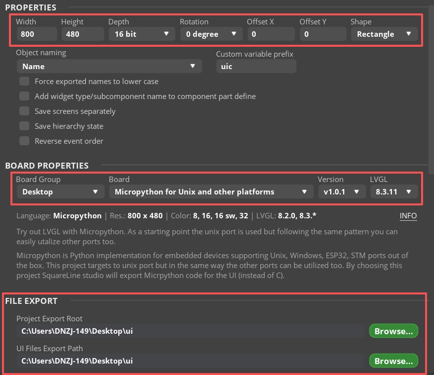
Open the SquareLine Studio and create a project. Select "Desktop"->"Micropython for Unix and other platform".

-
Set the name of the project, set the screen resolution to 800*480, set the color depth to 16bit, and keep other default settings. After setting, click CREATE to create the project.
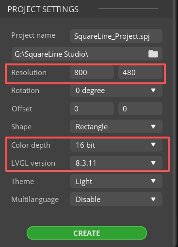
- 16-bit color depth: can represent 65,536 colors through RGB 5:6:5 sub-pixel representation, that is, each RGB channel occupies 5 bits and 1 bit (a total of 16 bits) to represent colors.
-
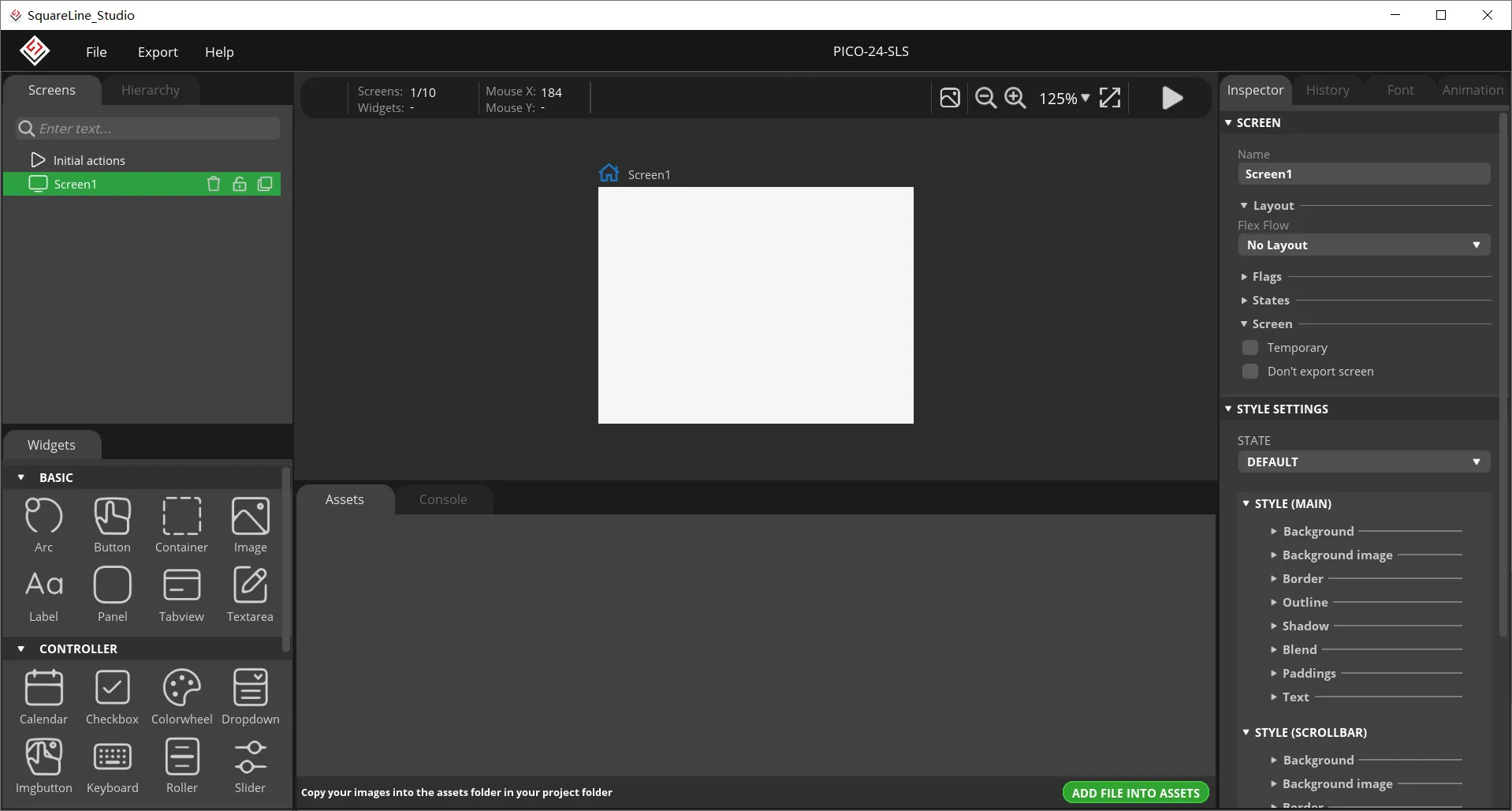
After creation, enter the following interface with a blank background.
-
In the "Assets" area, click "ADD FILE TO ASSETS" to add custom images or icons.
Please click
 to download the custom images used in this tutorial.
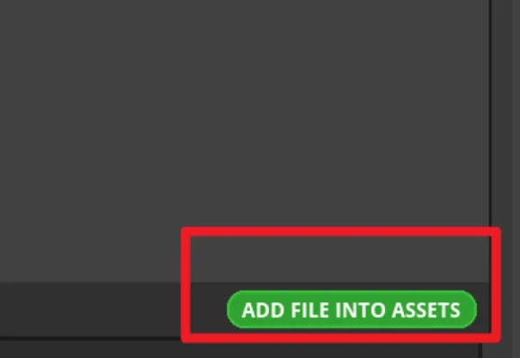
-
Add background.
Drag the image into the interface.
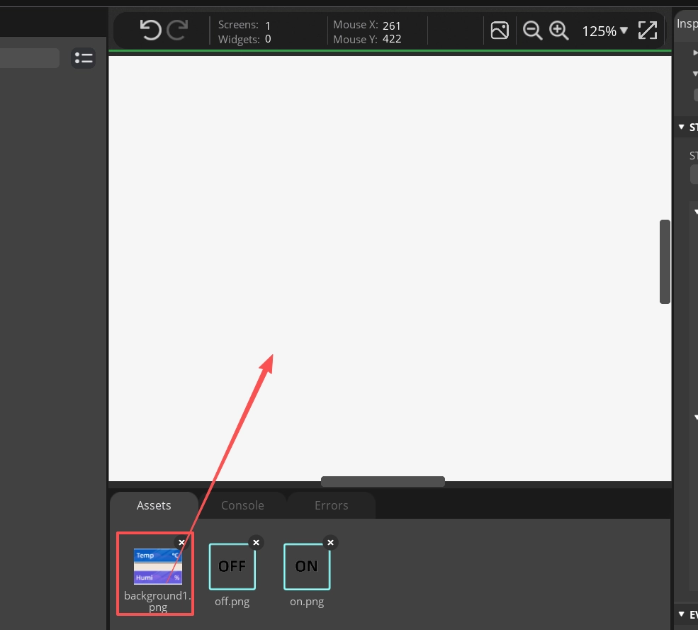
Select the fill background color (make sure not to select the image; this is for filling the main interface's background color).
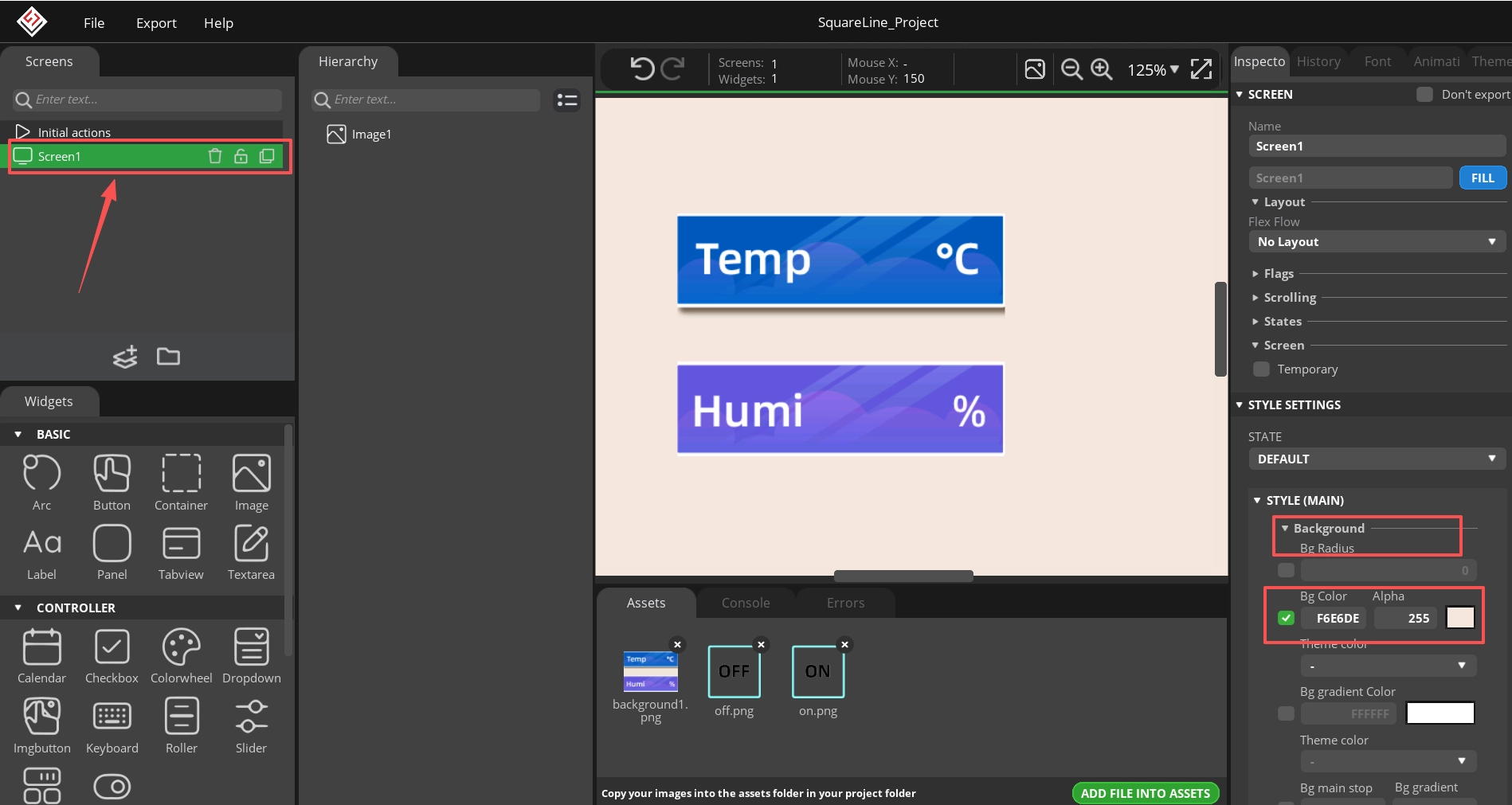
Adjust the position of the image.

Note: Because it requires a large amount of memory when running in Thonny IDE, the UI background resolution of this tutorial is small and not full screen, so it is necessary to modify the background to the same color as the image.
-
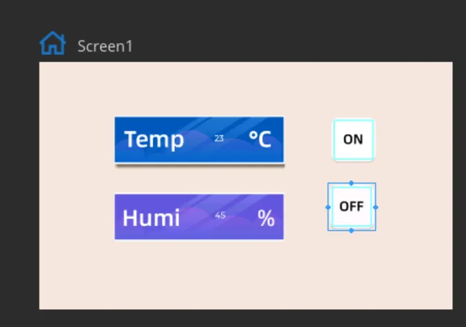
Add Label widget to show temperature and humidity value
Click "Label" in the "Widgets" area, and "Label1" will be added to the current Screen.
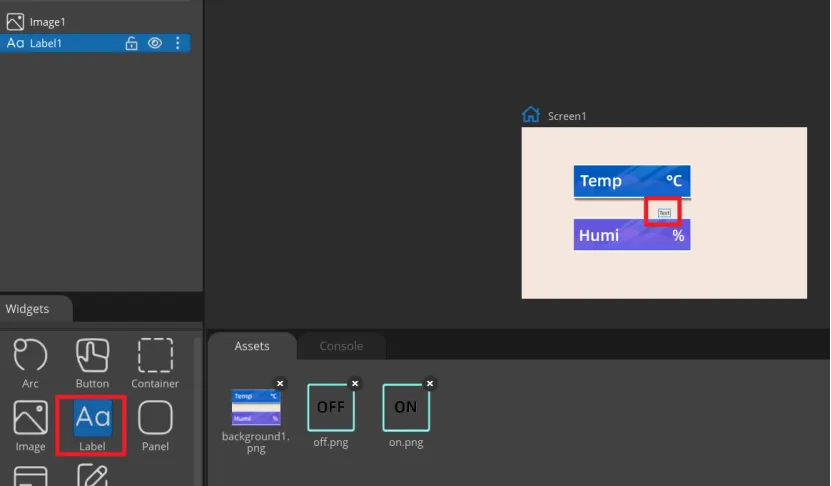
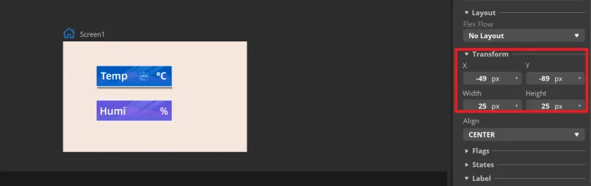
The content, position and size of the label can be adjusted by dragging the mouse. You can also directly enter numbers in the Inspector→LABEL→Transform to adjust. You can set the font color and other attributes in STYLE SETTING→STYLE(MAIN).
You can set the color and other attributes of the font in STYLE SETTING ->STYLE (MAIN).

Duplicate a Label2 to show humidity value.
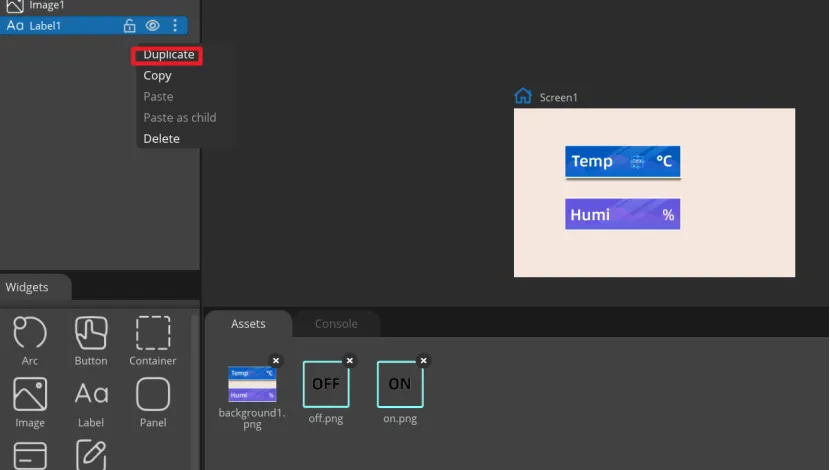
Adjust the position.
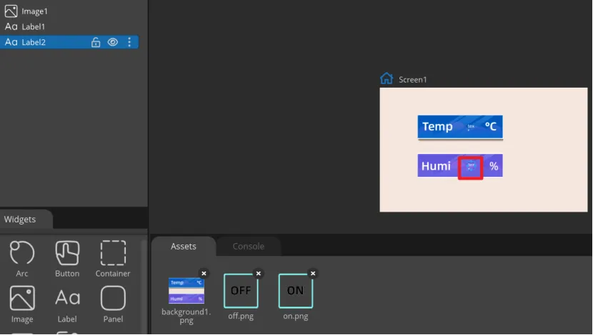
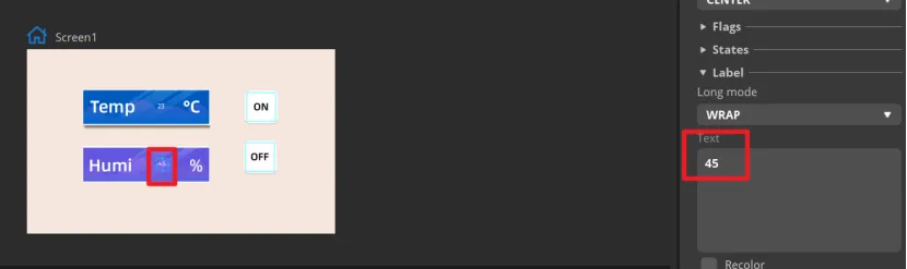
You can change the text of the label to set a default value.
-
Add Button widget to control the LED.
Click "Button" in the "Widgets" area, and "Button1" will be added to the current Screen.
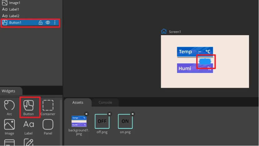
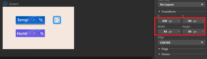
The position and size of the label can be adjusted by dragging the mouse. You can also directly enter numbers in the Inspector→BUTTON→Transform to adjust.
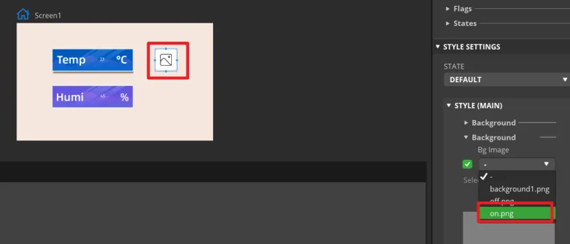
Add an identification symbol to the button. The button in this tutorial controls the LED switch, so you only need to mark the button "on" and "off". You can add LABEL widgets or add a background images to the button. This tutorial will demonstrate how to add a background image to a button.
Click the Button1, then find Inspector->STYLE SETTINGS ->STYLE(MAIN) ->Background, and select the image.
Duplicate a Button2 for "OFF".


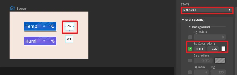
Set the status of the button to identify different states.
In "Inspector"->"STYLE SETTINGS"->"STATE", set display white background color by DEFAULT and red when on the PRESSED state.

-
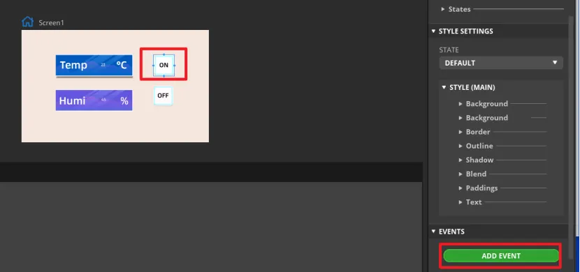
Add events to buttons.
Note: Because the button controls the on and off of the LED, we can add any event here to generate the code framework for the button event when exporting the UI file. We will modify the code of the button event to control the LED latter.
Select the button and click "ADD EVENT".
Select "released" as the trigger condition, select a trigger event in "Action". It will be modified in the generated program to achieve the LED control function.
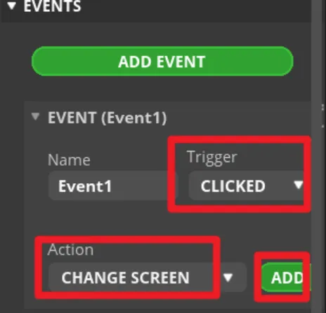
Complete the event. Here I choose to change the screen, and the screen to be switched is Screen1.
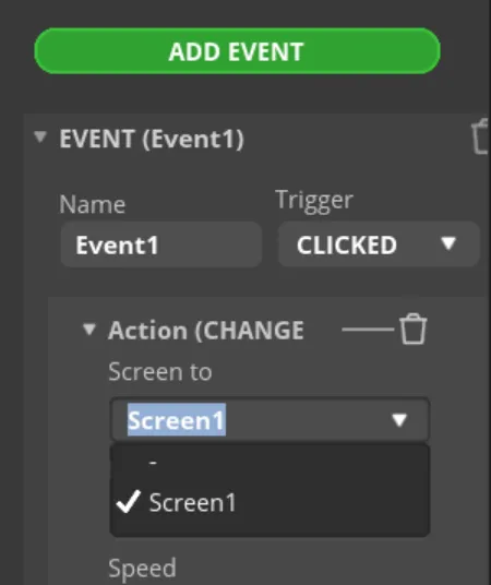
Make the same settings for the "OFF" button.
-
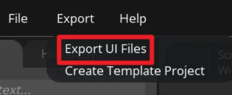
Export UI files.
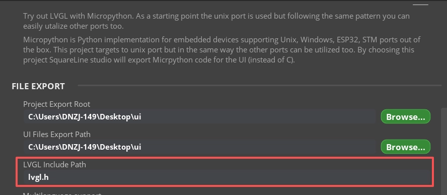
Click "File" -> "Project Settings" and make settings for the exported file.
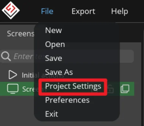
Set the export path of the file (set the path according to your own file).
Fill in lvgl.h in LVGL Include Path. Check "Flat export(exports all files to one folder )".
Then click "APPLY CHANGES".
Export UI files. The exported files will be in the path we set earlier.
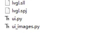
The UI file export is completed. Next we're going to learn about the main program and learn how to upload the code to the board with Thonny IDE.
Build the Project with Thonny IDE
Download Thonny IDE
-
Go to the website https://thonny.org/ and download the corresponding software version (here we take the Windows version as an example)
Note: If the latest version of Thonny cannot run this project, please roll back to version 4.1.7.(https://github.com/thonny/thonny/releases/tag/v4.1.7)

-
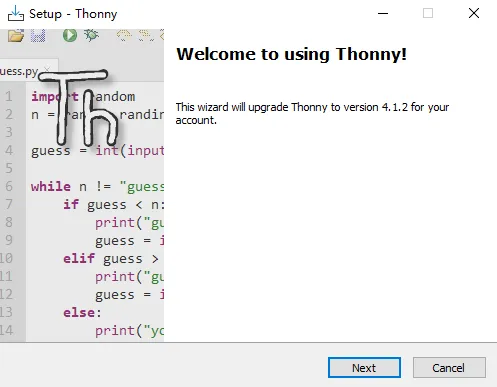
Double-click the downloaded exe file to install the software.
Upload firmware
Please click to download the bin file.
-
Connect the CrowPanel ESP32 HMI with your computer.
-
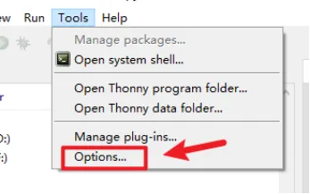
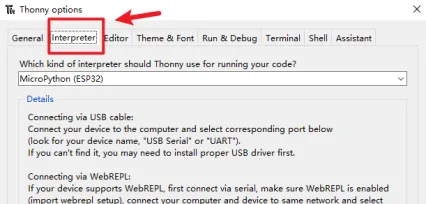
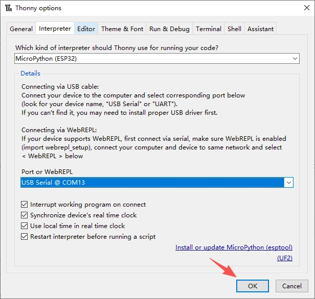
Open Thonny IDE and click "Tools"->"Options"->"Interpreter".
-
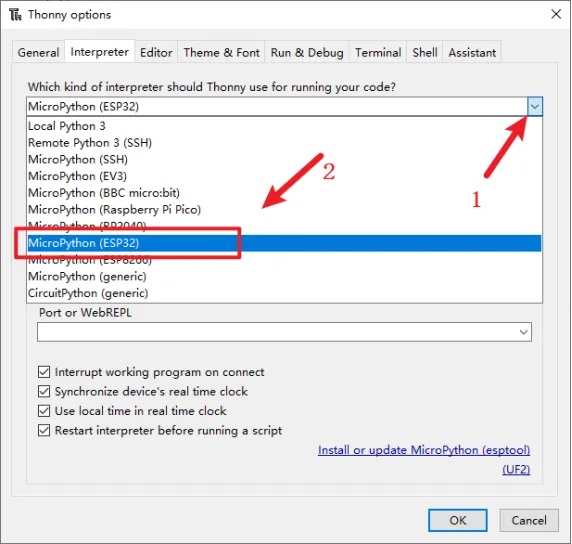
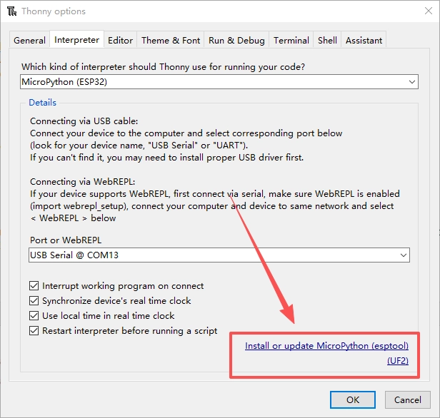
Select "MicroPython(ESP32)" for interpreter.
-
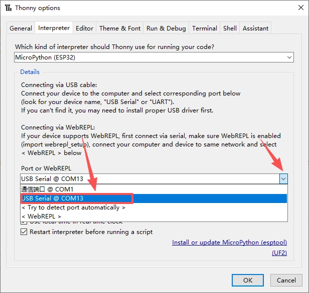
Select the corresponding serial port(or Try to detect port automatically).
-
Click "Install or update MicroPython (esptool)"
-
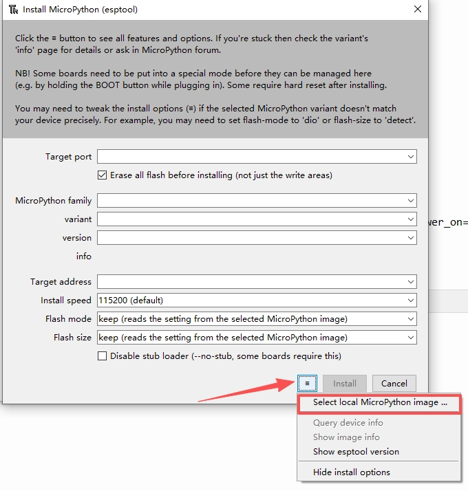
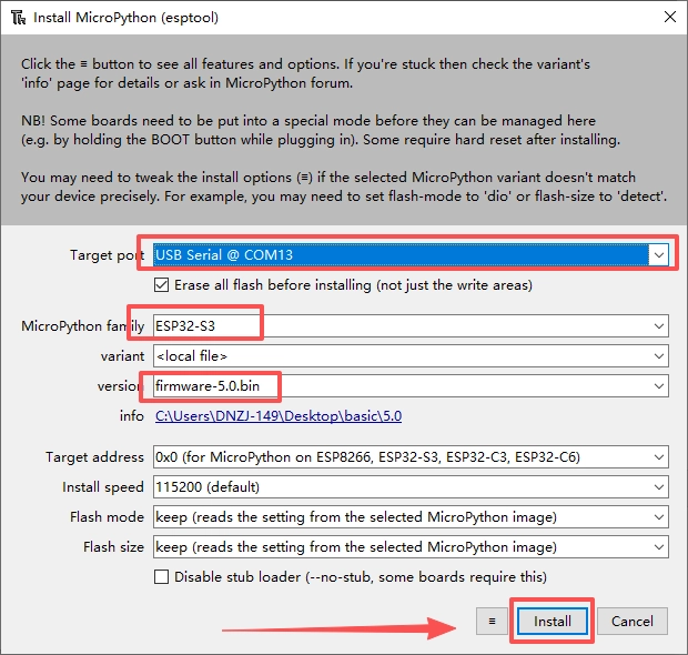
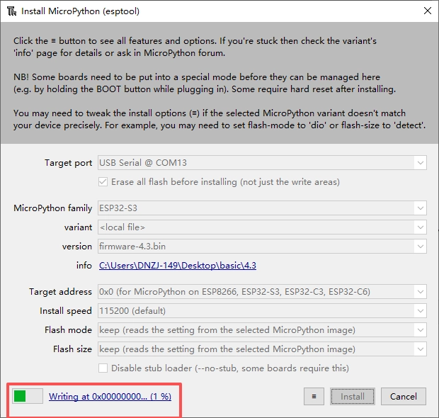
Click the icon with 3 lines, and click "select local MicroPython image...".Select the "firmware-5.0-A.bin" and install.
-
Waiting for downloading...
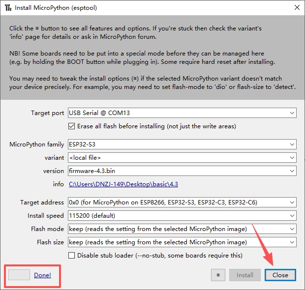
After successful addition, a boot.py file will appear in the lower-left corner.
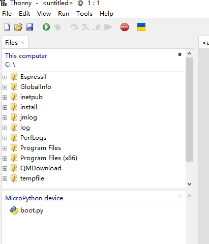
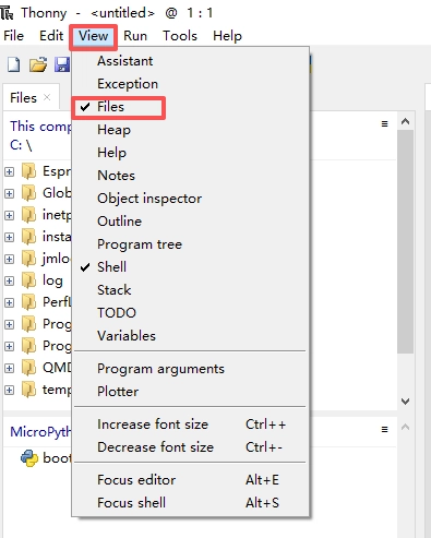
If it does not appear, check whether the extension files are enabled.
Upload the code
Please click to download the code file and libraries.
Upload the libraries
ui_image.py
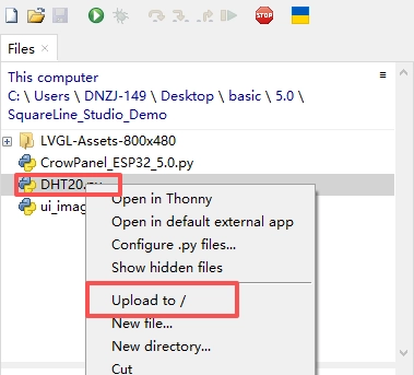
- In the upper left corner of the thonny, enter the path where ui_image.py is located, right-click ui_image.py, and click Upload to/

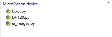
- ui_image.py is added to MicroPython device successfully.

- Import the DHT20.py file.
Upload the code
Double-click to open the main program.Click the "run" icon.
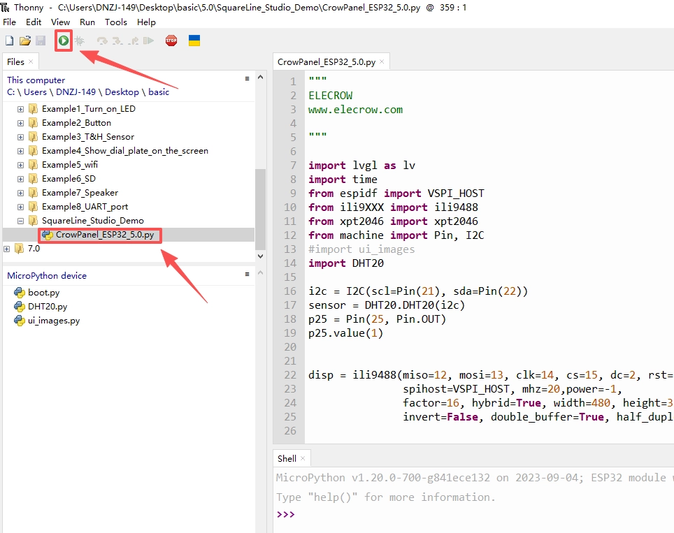
Successfully uploaded.

Code Explanation
Libraries imported in this example
import lvgl as lv
import lv_utils
import tft_config
import time
import fs_driver
import gt911
from machine import Pin, I2C
import ui_images
from DHT20 import DHT20
- lvgl: This is an open-source embedded graphics library used to create cross platform GUI. LVGL is written in C, but provides bindings for multiple languages, including Python. It supports multiple display types and input devices, making it ideal for touch screen applications on microcontrollers.
- lv_utils: This library may be an auxiliary library for LVGL, providing additional utilities or functions to help developers use LVGL more easily. Specific functions may include simplified API calls, universal configuration functions, etc.
- tft_config: This library may be used to configure TFT (Thin Film Transistor) displays. In embedded systems, TFT displays are commonly used to display graphical interfaces.The
tft_configlibrary may contain functions for initializing the display, setting resolution, color depth, and other configurations. - machine : This is a standard library for MicroPython used for interacting with hardware devices. It provides methods for accessing and controlling hardware interfaces such as GPIO (General Purpose Input/Output) pins, SPI (Serial Peripheral Interface) bus, I2C (Integrated Circuit Bus) of microcontrollers.
- time: This is the standard library in Python used for time related operations, such as pausing program execution (sleep function), retrieving the current time, etc.
- fs_deriver: This library may refer to a file system driver used to manage file systems on microcontrollers. It may include functions such as reading and writing files, directory operations, etc.
- ui_images: This library may be used to manage image resources in the user interface. It may include functions such as loading images into memory and displaying images on the GUI.
- GT911: This may be a touch controller library used to interact with the touch chip of the GT911 model and obtain touch events.
- DHT: This library is used to interact with temperature and humidity sensors of DHT models, reading temperature and humidity data.
Basic Definition
Set up LED and sensor.
pin38 = Pin(38, Pin.OUT)# Set GPIO pin 38 to output mode
pin38.value(0)

#Initialize DHT20 temperature and humidity sensor
i2c = I2C(1, scl=Pin(20), sda=Pin(19), freq=400000)

sensor = DHT20(i2c)
Screen and touch driver initialization
# Define the width and height of the LCD display
WIDTH = 800
HEIGHT = 480

# tft drvier
tft = tft_config.config()

# touch drvier
# Initialize I2C bus for touch driver communication
i2c = I2C(1, scl=Pin(20), sda=Pin(19), freq=400000) # Create an I2C object, specify the I2C port number, clock and data line pins, and frequency

# Initialize GT911 touch controller and set screen resolution
tp = gt911.GT911(i2c, width=800, height=480) # Create GT911 object, pass in I2C bus and screen resolution

# Set screen rotation direction of touch controller
tp.set_rotation(tp.ROTATION_INVERTED) # Set rotation direction to inverted

# Initialize LVGL graphics library
lv.init() # Initialize LVGL

# Check if LVGL event loop is running, if not, create one
if not lv_utils.event_loop.is_running():
event_loop = lv_utils.event_loop() # Create event loop object
print(event_loop.is_running()) # Print if event loop is running

# Create display driver buffer
disp_buf0 = lv.disp_draw_buf_t() # Create display driver buffer object
buf1_0 = bytearray(WIDTH * 50) # Allocate buffer memory, where WIDTH is the width of the screen
disp_buf0.init(buf1_0, None, len(buf1_0) // lv.color_t.__SIZE__) # Initialize buffer

# Register display driver
disp_drv = lv.disp_drv_t() # Create display driver object
disp_drv.init() # Initialize display driver
disp_drv.draw_buf = disp_buf0 # Set the display driver buffer
disp_drv.flush_cb = tft.flush # Set refresh callback function to refresh display content to TFT
disp_drv.hor_res = WIDTH # Set the horizontal resolution of the display driver
disp_drv.ver_res = HEIGHT # Set the vertical resolution of the display driver
# disp_drv.user_data = {"swap": 0} # Optional: Set user data, such as swapping color channels
disp0 = disp_drv.register() # Register display driver
lv.disp_t.set_default(disp0) # Set default display driver

# Initialize touch input device driver
indev_drv = lv.indev_drv_t() # Create input device driver object
indev_drv.init() # Initialize input device driver
indev_drv.disp = disp0 # Associate display driver
indev_drv.type = lv.INDEV_TYPE.POINTER # Set input device type to pointer
indev_drv.read_cb = tp.lvgl_read # Set callback function for reading touch data
indev = indev_drv.register() # Register input device driver
UI code
This part copies the code of ui.py generated by Squareline Studio. We need to modify the part that control the button.
Modify from
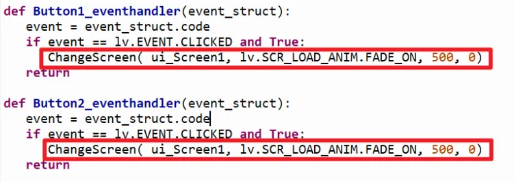
to
def Button1_eventhandler(event_struct):
   event = event_struct.code
   if event == lv.EVENT.CLICKED and True:
      pin38.value(1)
   return

def Button2_eventhandler(event_struct):
   event = event_struct.code
   if event == lv.EVENT.CLICKED and True:
      pin38.value(0)
   return
GPIO Examples
Please click to download the code files.
Note! You need to reflash the firmware for each project, otherwise errors may occur.
Example 1 Turn on/off the LED automatically in a loop
Connect an LED module to the D port(pin38) of ESP32 5.0'' HMI, and upload the following code. The LED will turn on and off in a loop.
#Make by Elecrow
#Web:www.elecrow.com

import time
from machine import Pin
pin38 = Pin(38, Pin.OUT)
while True:

    pin38.value(1)
    time.sleep(0.5)
    pin38.value(0)
    time.sleep(0.5)
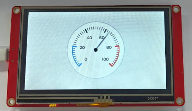
Example 2 Show dial plate on the screen
Upload the following code to the module, there will be a dial plate show on the screen.
#Make by Elecrow
#Web:www.elecrow.com
import lvgl as lv
import lv_utils
import tft_config
import time
import fs_driver
import gt911
from machine import Pin, I2C

WIDTH = 800
HEIGHT = 480


# tft drvier
tft = tft_config.config()

# touch drvier
i2c = I2C(1, scl=Pin(20), sda=Pin(19), freq=400000)

tp = gt911.GT911(i2c, width=800, height=480)
tp.set_rotation(tp.ROTATION_NORMAL)

lv.init()

if not lv_utils.event_loop.is_running():
    event_loop=lv_utils.event_loop()
    print(event_loop.is_running())

# create a display 0 buffer
disp_buf0 = lv.disp_draw_buf_t()
buf1_0 = bytearray(WIDTH * 50)
disp_buf0.init(buf1_0, None, len(buf1_0) // lv.color_t.__SIZE__)

# register display driver
disp_drv = lv.disp_drv_t()
disp_drv.init()
disp_drv.draw_buf = disp_buf0
disp_drv.flush_cb = tft.flush
disp_drv.hor_res = WIDTH
disp_drv.ver_res = HEIGHT
# disp_drv.user_data = {"swap": 0}
disp0 = disp_drv.register()
lv.disp_t.set_default(disp0)

# touch driver init
indev_drv = lv.indev_drv_t()
indev_drv.init()
indev_drv.disp = disp0
indev_drv.type = lv.INDEV_TYPE.POINTER
indev_drv.read_cb = tp.lvgl_read
indev = indev_drv.register()


# 1. Create a display screen. Will need to display the component added to the screen to display
scr = lv.obj()  # scr====> screen
fs_drv = lv.fs_drv_t()
fs_driver.fs_register(fs_drv, 'S')
scr = lv.scr_act()
scr.clean()


# 2. Encapsulate the component to display
class MyWidget():
    def __init__(self, scr):
        # 1. Create the dashboard object
        self.meter = lv.meter(scr)
        self.meter.center()
        self.meter.set_size(200, 200)  # width: 200 height: 200

        # 2. To create calibration object
        scale = self.meter.add_scale()

        self.meter.set_scale_ticks(scale, 51, 2, 10, lv.palette_main(lv.PALETTE.GREY))

        self.meter.set_scale_major_ticks(scale, 10, 4, 15, lv.color_black(), 20)

        # 3. Add warning scale line

        blue_arc = self.meter.add_arc(scale, 2, lv.palette_main(lv.PALETTE.BLUE), 0)
        self.meter.set_indicator_start_value(blue_arc, 0)
        self.meter.set_indicator_end_value(blue_arc, 20)


        blue_arc_scale = self.meter.add_scale_lines(scale, lv.palette_main(lv.PALETTE.BLUE), lv.palette_main(lv.PALETTE.BLUE), False, 0)
        self.meter.set_indicator_start_value(blue_arc_scale, 0)
        self.meter.set_indicator_end_value(blue_arc_scale, 20)


        red_arc = self.meter.add_arc(scale, 2, lv.palette_main(lv.PALETTE.RED), 0)
        self.meter.set_indicator_start_value(red_arc, 80)
        self.meter.set_indicator_end_value(red_arc, 100)


        red_arc_scale = self.meter.add_scale_lines(scale, lv.palette_main(lv.PALETTE.RED), lv.palette_main(lv.PALETTE.RED), False, 0)
        self.meter.set_indicator_start_value(red_arc_scale, 80)
        self.meter.set_indicator_end_value(red_arc_scale, 100)

        # 4. meter needle
        self.indic = self.meter.add_needle_line(scale, 4, lv.palette_main(lv.PALETTE.GREY), -10)

        # 5. Creating animated objects
        a = lv.anim_t()
        a.init()
        a.set_var(self.indic)
        a.set_values(0, 100)
        a.set_time(2000)
        a.set_repeat_delay(100)
        a.set_playback_time(500)
        a.set_playback_delay(100)
        a.set_repeat_count(lv.ANIM_REPEAT.INFINITE)
        a.set_custom_exec_cb(self.set_value)
        lv.anim_t.start(a)

    def set_value(self, anmi_obj, value):
        """Animation callbacks"""
        self.meter.set_indicator_value(self.indic, value)


# 3. Create the component to display
MyWidget(scr)

# 4. Displays the contents of the screen object
lv.scr_load(scr)


# ------------------------------ Guard dog to restart ESP32 equipment --start------------------------
try:
    from machine import WDT
    wdt = WDT(timeout=1000)  # enable it with a timeout of 2s
    print("Hint: Press Ctrl+C to end the program")
    while True:
        wdt.feed()
        time.sleep(0.9)
except KeyboardInterrupt as ret:
    print("The program stopped running, ESP32 has restarted...")
    tft.deinit()
    time.sleep(10)
# ------------------------------ Guard dog to restart ESP32 equipment --stop-------------------------
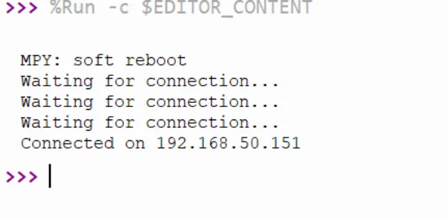
Example 3 Connect WiFi
Upload the following code to ESP32 HMI(note to modify the WiFi ssid and password to yours)
import network
import time

def connect():
    ssid = 'yanfa_software'
    password = 'yanfa-123456'

    wlan = network.WLAN(network.STA_IF)  # Create a WLAN object in station mode
    wlan.active(True)  # Activate the network interface
    wlan.connect(ssid, password)  # Connect to the specified WiFi network

    while not wlan.isconnected():  # Wait for the connection to be established
        print('Waiting for connection...')
        time.sleep(1)

    print('Connected on {ip}'.format(ip=wlan.ifconfig()[0]))  # Print the IP address

connect()
Running result:
Example 4 Initialize SD card
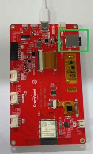
Note: Please use an SD card formatted in FAT; otherwise, it may not be recognized.
import machine
import os
import sdcard
import uos

#  SD Card Initialization
def init_sd():
    # Creating SPI Objects
    spi = machine.SPI(2, baudrate=1000000, polarity=0, phase=0, sck=machine.Pin(12), mosi=machine.Pin(11), miso=machine.Pin(13))
    cs = machine.Pin(10, machine.Pin.OUT)

    # SD Card Initialization
    sd = sdcard.SDCard(spi, cs)
    vfs = uos.VfsFat(sd)
    uos.mount(vfs, "/sd")

    print("SD card initialization complete")
    print("List of documents:", os.listdir("/sd"))

# write to a file
def write_file(filename, data):
    with open("/sd/" + filename, "w") as file:
        file.write(data)
    print("Data has been written to file:", filename)

# Read file
def read_file(filename):
    with open("/sd/" + filename, "r") as file:
        data = file.read()
    print("readout:", data)
    return data

# Example: Initialize SD card and read/write files
def main():
    init_sd()

    filename = "example.txt"
    data = "Hello, SD Card!"

    write_file(filename, data)
    read_file(filename)

if __name__ == "__main__":
    main()
Example 5 Playing music
Connect a speaker to the ESP32 HMI. Upload the following code.
import os
import math
import struct
from machine import I2S
from machine import Pin

# ========== NOTE FREQUENCY TABLE (C4 = 261.63Hz) ==========
NOTES = {
    'C4': 261.63, 'D4': 293.66, 'E4': 329.63, 'F4': 349.23,
    'G4': 392.00, 'A4': 440.00, 'B4': 493.88,
    'C5': 523.25, 'D5': 587.33, 'E5': 659.25, 'F5': 698.46,
    'G5': 783.99, 'A5': 880.00, 'B5': 987.77,
    'REST': 0,
}

# ========== HAPPY BIRTHDAY MELODY ==========
# Each element: (note, duration_in_beats)
# Beat unit is a quarter note
MELODY = [
    ('G4', 0.5), ('G4', 0.5), ('A4', 1.0), ('G4', 1.0), ('C5', 1.0), ('B4', 2.0),
    ('G4', 0.5), ('G4', 0.5), ('A4', 1.0), ('G4', 1.0), ('D5', 1.0), ('C5', 2.0),
    ('G4', 0.5), ('G4', 0.5), ('G5', 1.0), ('E5', 1.0), ('C5', 1.0), ('B4', 1.0), ('A4', 2.0),
    ('F5', 0.5), ('F5', 0.5), ('E5', 1.0), ('C5', 1.0), ('D5', 1.0), ('C5', 2.0),
]

def make_tone(rate, bits, frequency, duration_ms):
    """Generate sine wave samples for a given frequency and duration."""
    if frequency == 0:
        # Rest note: generate silence
        samples = bytearray(rate * (bits // 8) * duration_ms // 1000)
        return samples

    samples_per_cycle = int(rate / frequency)
    sample_size_in_bytes = bits // 8
    total_samples = int(rate * duration_ms / 1000)

    # Ensure total samples is an integer multiple of samples_per_cycle to avoid clicking
    cycles = total_samples // samples_per_cycle
    total_samples = cycles * samples_per_cycle

    samples = bytearray(total_samples * sample_size_in_bytes)
    volume_reduction_factor = 8  # Adjust volume level
    amplitude = int((pow(2, bits) // 2 - 1) / volume_reduction_factor)

    if bits == 16:
        fmt = "<h"
    else:
        fmt = "<l"

    for i in range(total_samples):
        sample = int(amplitude * math.sin(2 * math.pi * i / samples_per_cycle))
        struct.pack_into(fmt, samples, i * sample_size_in_bytes, sample)

    return samples

def make_silence(rate, bits, duration_ms):
    """Generate silence samples."""
    sample_size = bits // 8
    num_samples = rate * duration_ms // 1000
    return bytearray(num_samples * sample_size)

# ========== BOARD CONFIGURATION ==========
if os.uname().machine.count("PYBv1"):
    SCK_PIN = "Y6"
    WS_PIN = "Y5"
    SD_PIN = "Y8"
    I2S_ID = 2
    BUFFER_LENGTH_IN_BYTES = 2000

elif os.uname().machine.count("PYBD"):
    import pyb
    pyb.Pin("EN_3V3").on()  # Provide 3.3V on 3V3 output pin

    SCK_PIN = "Y6"
    WS_PIN = "Y5"
    SD_PIN = "Y8"
    I2S_ID = 2
    BUFFER_LENGTH_IN_BYTES = 2000

elif os.uname().machine.count("ESP32"):
    SCK_PIN = 42
    WS_PIN = 18
    SD_PIN = 17
    I2S_ID = 0
    BUFFER_LENGTH_IN_BYTES = 2000

elif os.uname().machine.count("Raspberry"):
    SCK_PIN = 16
    WS_PIN = 17
    SD_PIN = 18
    I2S_ID = 0
    BUFFER_LENGTH_IN_BYTES = 1000

elif os.uname().machine.count("MIMXRT"):
    SCK_PIN = 4
    WS_PIN = 3
    SD_PIN = 2
    I2S_ID = 2
    BUFFER_LENGTH_IN_BYTES = 2000

else:
    print("Warning: program not tested with this board")

# ========== AUDIO CONFIGURATION ==========
TEMPO_MS = 400  # Duration of one beat in milliseconds
SAMPLE_SIZE_IN_BITS = 16
FORMAT = I2S.MONO  # Only mono supported in this example
SAMPLE_RATE_IN_HZ = 22_050

audio_out = I2S(
    I2S_ID,
    sck=Pin(SCK_PIN),
    ws=Pin(WS_PIN),
    sd=Pin(SD_PIN),
    mode=I2S.TX,
    bits=SAMPLE_SIZE_IN_BITS,
    format=FORMAT,
    rate=SAMPLE_RATE_IN_HZ,
    ibuf=BUFFER_LENGTH_IN_BYTES,
)

# ========== PRE-GENERATE ALL NOTE SAMPLES ==========
print("Generating audio data...")

# Pre-generate note cache to avoid real-time computation during playback
note_cache = {}
for note_name, freq in NOTES.items():
    for beats in [0.5, 1.0, 2.0]:
        duration_ms = int(TEMPO_MS * beats)
        key = (note_name, beats)
        note_cache[key] = make_tone(SAMPLE_RATE_IN_HZ, SAMPLE_SIZE_IN_BITS, freq, duration_ms)

# Short silence between notes to prevent slurring
GAP_MS = 50
silence = make_silence(SAMPLE_RATE_IN_HZ, SAMPLE_SIZE_IN_BITS, GAP_MS)

# ========== PLAYBACK ==========
print("==========  PLAYING HAPPY BIRTHDAY  ==========")
print("Press Ctrl+C to stop")

try:
    while True:
        for note_name, beats in MELODY:
            key = (note_name, beats)
            samples = note_cache[key]

            # Write note samples
            audio_out.write(samples)

            # Add brief silence between notes for clearer rhythm
            audio_out.write(silence)

        # Pause 1 second after each full melody loop
        audio_out.write(make_silence(SAMPLE_RATE_IN_HZ, SAMPLE_SIZE_IN_BITS, 1000))

except (KeyboardInterrupt, Exception) as e:
    print("Stopped: {} {}".format(type(e).__name__, e))

# Cleanup
audio_out.deinit()
print("Done")
For more demo of the i2s speaker please refer to: https://github.com/miketeachman/micropython-i2s-examples
Example 6 Initialize UART port
Upload the following code
import machine
import time

# Initialize UART
uart = machine.UART(1, baudrate=115200, tx=43, rx=44)

def send_data(data):
    uart.write(data)  # Send data via UART
    print("Sent:", data)

def receive_data():
    if uart.any():  # Check for readable data
        data = uart.read()  # retrieve data
        print("Received:", data)
        return data
    return None

# Example: Sending and Receiving Data
send_data('Hello, UART!\n')

while True:
    received = receive_data()
    if received:
        # do something about it
        pass
    time.sleep(1)
Running result:
