Currency
Toggle Nav


THE ANALOG SYNTHESIZER PCB
$12.00
Availability:
In stock
SKU
PDE25412P
Weight
20g
Related Products:


×
 Add to cart successfully!


Customers Who View This Item Also Bought
ANALOG is an analog synthesizer composed of 100% analog circuits.
Description
ANALOG is an analog synthesizer composed of 100% analog circuits.
ANALOG is made up of only very common parts. You can collect all the parts at general electronic parts stores and general mail order sites. Would you like to become an analog synth builder?
1.First of all, let's collect parts.
Align the parts in the Parts List below.
You can also collect all parts at general electronic parts stores and general web order sites.
|
|
Value |
Package |
Parts |
Qty |
|
NPN Transistror |
2SC1815 Y |
TO92-ECB |
T1, T2, T3, T4, T6, T7, T8, T9, T10, T11, T12, T13, T14, T15, T16 |
15 |
|
PNP Transistror |
2SA1015 Y |
TO92-ECB |
T5 |
1 |
|
RESISTOR |
100k |
0207/7 |
R1, R2, R12, R14, R17, R18, R19, R20, R21, R22, R26, R27, R29, R30, R41, R44, R49, R50, R51, R52 |
20 |
|
RESISTOR |
10k |
0207/7 |
R3, R4, R16, R23, R28, R47, R48, R53, R54, R55 |
10 |
|
RESISTOR |
1k |
0207/7 |
R6, R7, R8, R9, R10, R11, R13, R15, R31, R32, R33, R34, R35, R36, R37, R38, R39, R40, R42, R43, R45, R46 |
22 |
|
VR |
10k |
B25P |
R5, R24, R25 |
3 |
|
Potentiometer |
10k |
16K4 |
POT1, POT3, POT4, POT5, POT7 |
5 |
|
Potentiometer |
1M |
16K4 |
POT2 |
1 |
|
CAPACITOR |
1n |
C050-024X044 |
C1, C3 |
2 |
|
CAPACITOR |
100n |
C050-024X044 |
C5, C6, C7, C8 |
4 |
|
CAPACITOR |
1u |
C050-024X044 |
C2, C9, C10, C11 |
4 |
|
CAPACITOR |
10u |
C050-024X044 |
C4, C12, C13 |
3 |
|
OPAMP |
LM358N |
DIL08 |
IC1, IC3, IC4, IC5 |
4 |
|
OPAMP(FET) |
TL072P |
DIL08 |
IC2 |
1 |
|
SW |
TACT SWITCH |
B3F-10XX |
S1 |
1 |
|
LED3MM |
LED |
LED3MM |
LED |
1 |
|
OPAMP SOCKET |
8P |
DIL08 |
|
5 |
|
3.5mm |
JACK |
|
CV_IN, GATE_IN, VCC, VSS |
3 |
|
Toggle SW |
POWER SWITCH |
|
|
1 |
|
006P 9V |
BATT SANP |
|
|
1 |
|
KNOB |
KNOB |
|
|
6 |
|
HAMMOND CASE |
1590BB |
|
|
1 |
|
WIRE |
15cm |
|
|
1 |
2.Make
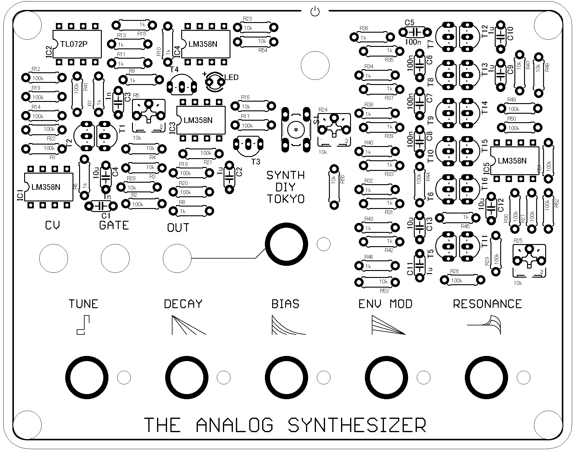
① Referring to the figure, place the electronic components on the board and solder them.
< a thing to note>
*IC and transistors are not soldered directly, but are recommended to use sockets.
Make sure that the parts are below 230 degrees Celsius and within 10 seconds.
In particular, please note that the operational amplifier is easily damaged by heat.
*POT2 is a 1MΩ potentiometer, others are 10k.
*Only IC2 is TL072 (high-impedance input type), and LM358 (single-supply type) is used for others.
② About the wiring on the back side
There are multiple putts on the back. Please wire as follows.
VCC Connect to the center terminal of the power switch.
VSS Connect with the negative side of the battery snap.
The positive end of the battery snap is routed to the other side of the power switch.
CV_IN CV Input terminals (3.5mm jack) to the chip side.
GATE_IN GATE Input terminals (3.5mm jack) to the chip side.
OUT Audio output jack (3.5mm jack) to the chip side.
<Tips>
If you think it's completed but it doesn't work, try the following.
☑ Try to remelt the solder
→ solder may not be fused to the part
Be careful not to let the temperature rise too high so that the parts do not break.
☑ Make sure the soldered parts are not wrong
☑ Make sure that the wires to the jack are connected to the chip.
3.Adjust
VCF Adjustment
(1) Set Cutoff to the minimum value.
(2) Turn R25 to the right until you hear a sound.
(3) Turn R25 to the left and stop immediately after the sound stops. (It is around 12 o'clock.) )
(4) Turn the cutoff all the way to the right.
(5) Press and hold ENV TRG SW.
(6) Turn R24 to the left.
(7) Turn R24 to the right. Stop immediately after the sound stops changing. (It is around 8 o'clock.) )
VCO Tuning
(1) Connect to the CV device and continue to input the octave pitch.
(2) Adjust R5 until the octave fits. (The approximate direction is from 9 o'clock to 12 o'clock.) )
Write Your Own Review