Currency
Toggle Nav


THE ANALOG SYNTHESIZER XL PCB
$22.00
Availability:
In stock
SKU
PDE25413P
Weight
30g
Related Products:


×
 Add to cart successfully!


Customers Who View This Item Also Bought
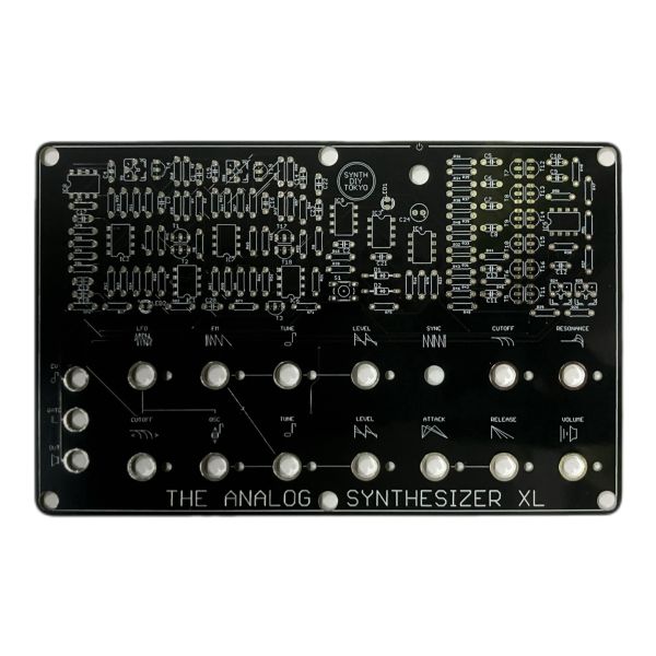
ANALOG is an analog synthesizer kit consisting of 100% analog circuitry.
The XL version has 2OSC, 1VCF, 1LFO, and 1ENV, making it a full-fledged synthesizer.
ANALOG is an analog synthesizer kit consisting of 100% analog circuitry.
ANALOG consists only of very common parts. You can also collect all parts at general electronic parts stores and general mail order sites.
The XL version has 2OSC, 1VCF, 1LFO, and 1ENV, making it a full-fledged synthesizer.
1.Collect
First of all, let's collect parts.
Align the parts in the Parts List below.
ANALOG consists only of electronic components that are very common in Japan.
You can also collect all parts at general electronic parts stores and general mail order sites.

2.Make
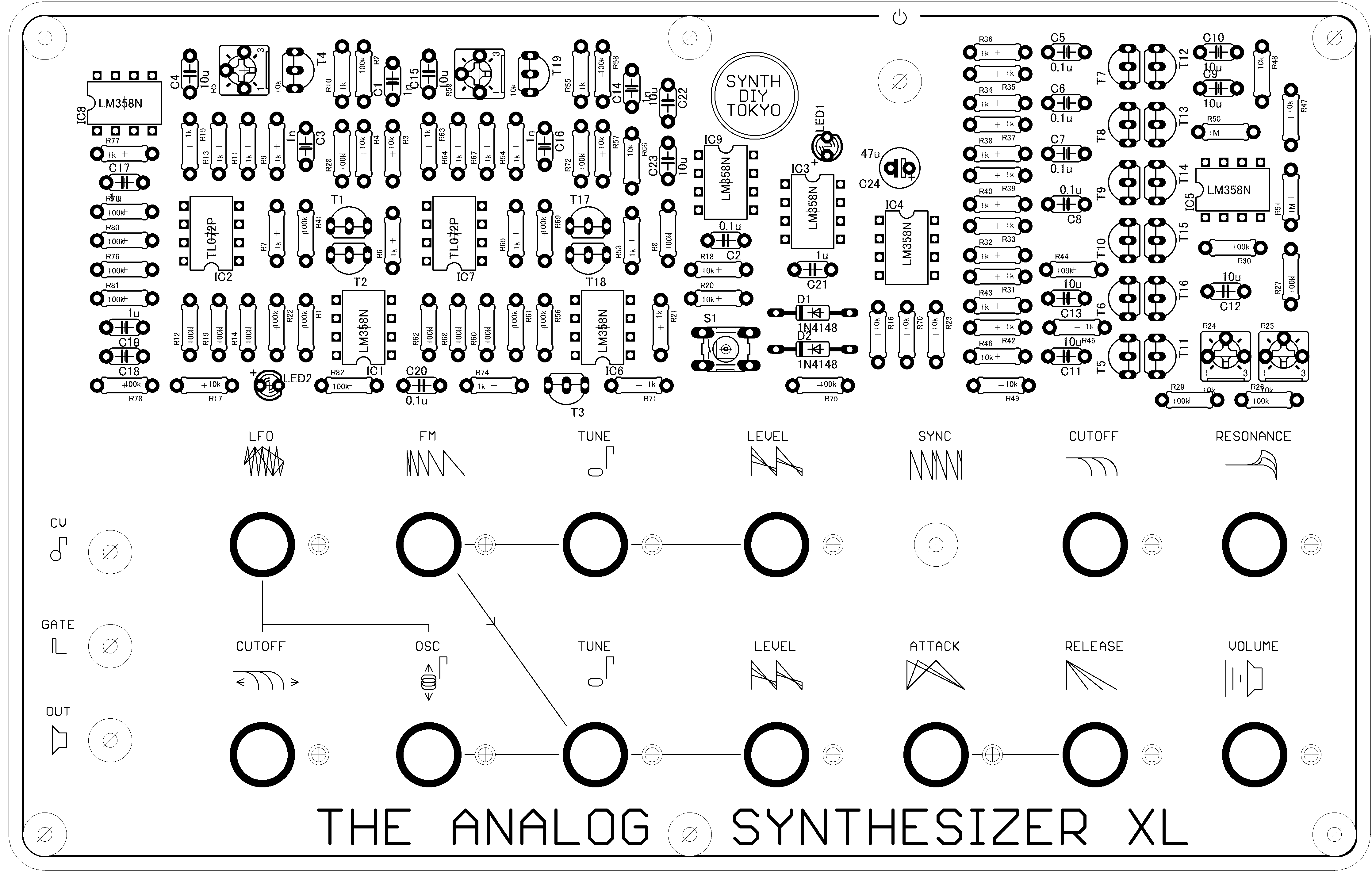
① Referring to the figure, place the electronic components on the board and solder them.
< a thing to note>
*IC and transistors are not soldered directly, but are recommended to use sockets.
Make sure that the parts are below 230 degrees Celsius and within 10 seconds.
In particular, please note that the operational amplifier is easily damaged by heat.
② About the wiring on the back side
There are multiple putts on the back. Please wire as follows.
VCC Connect to the center terminal of the power switch.
VSS Connect with the negative side of the battery snap.
The positive end of the battery snap is routed to the other side of the power switch.
CV_IN CV Input terminals (3.5mm jack) to the chip side.
GATE_IN GATE Input terminals (3.5mm jack) to the chip side.
OUT Audio output jack (3.5mm jack) to the chip side.
<Tips>
If you think it's completed but it doesn't work, try the following.
☑ Try to remelt the solder
→ solder may not be fused to the part
Be careful not to let the temperature rise too high so that the parts do not break.
☑ Make sure the soldered parts are not wrong
☑ Make sure that the wires to the jack are connected to the chip.
< Caution >
● If the battery is used incorrectly, it may generate heat, rupture, or leak. Please note the following:
● Set + / − (plus / minus) correctly.
● After use, remove the battery and store it.
● If you notice any abnormalities such as the main unit or battery becoming hot or emitting smoke, stop using it immediately and remove the battery.
● Keep out of reach of small children.
● Since we use parts that are vulnerable to static electricity, please put them in an antistatic bag when storing.
3. Adjustment
VCF Adjustment
(1) Set Cutoff to the minimum value.
(2) Turn R25 to the right until you hear a sound.
(3) Turn R25 to the left and stop immediately after the sound stops. (It is around 12 o'clock.) )
(4) Turn the cutoff all the way to the right.
(5) Press and hold ENV TRG SW.
(6) Turn R24 to the left.
(7) Turn R24 to the right. Stop immediately after the sound stops changing. (It is around 8 o'clock.) )
VCO1 Adjustment
1. Set the LEVEL of VCO2 to 0.
2.Connect to the CV device and continue to input the octave pitch.
3.Adjust R5 until the octave fits. (The approximate direction is from 9 o'clock to 12 o'clock.) )
VCO2 Adjustment
1. Set the LEVEL of VCO1 to 0.
2.Connect to the CV device and continue to input the octave pitch.
3.Adjust R59 until the octave fits. (The approximate direction is from 9 o'clock to 12 o'clock.) )
Write Your Own Review