
An infrared thermometer is an essential tool for rapid, accurate, and contactless temperature measurements. I used this tech to create a DIY smart coaster. That project inspired me to build a wearable infrared thermometer ring.
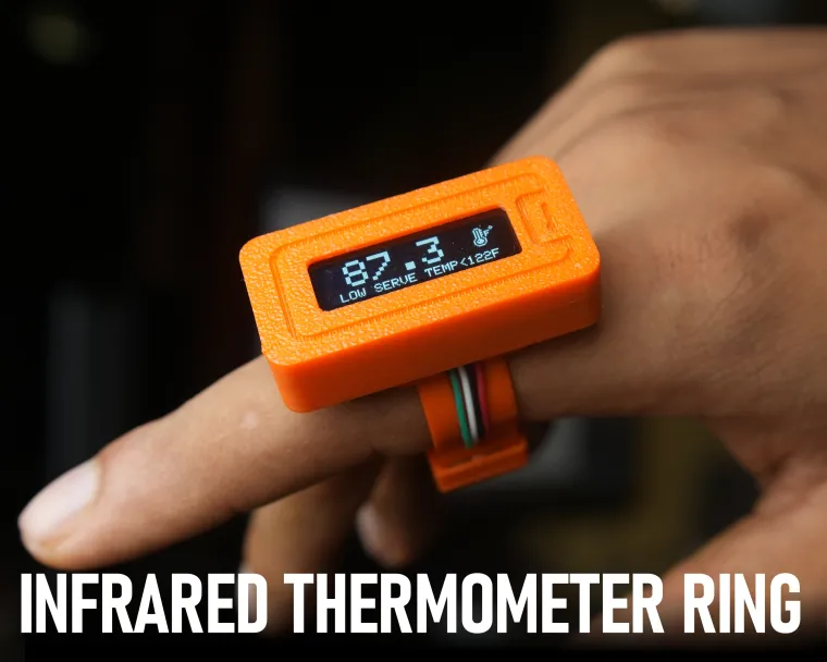
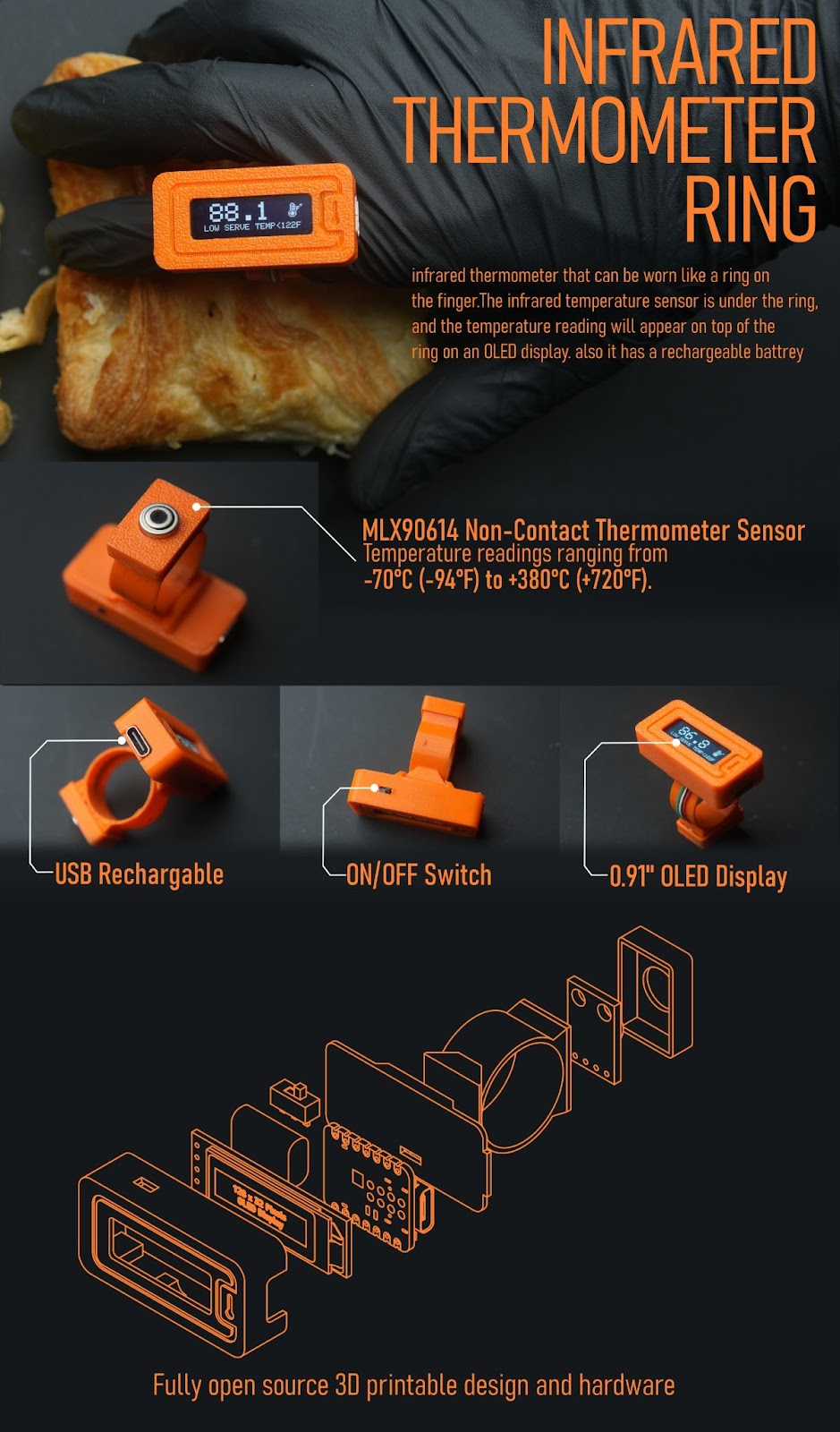
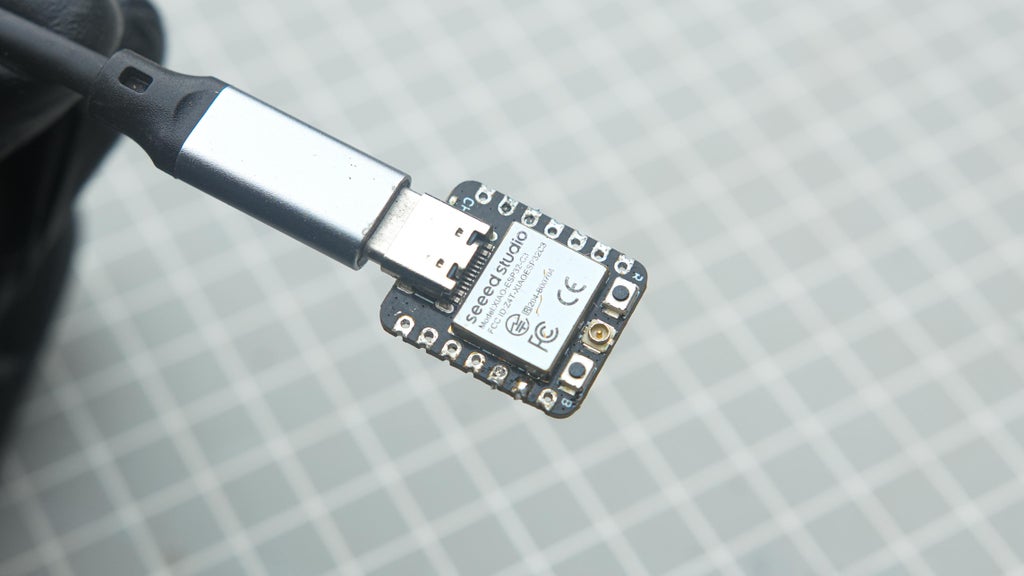
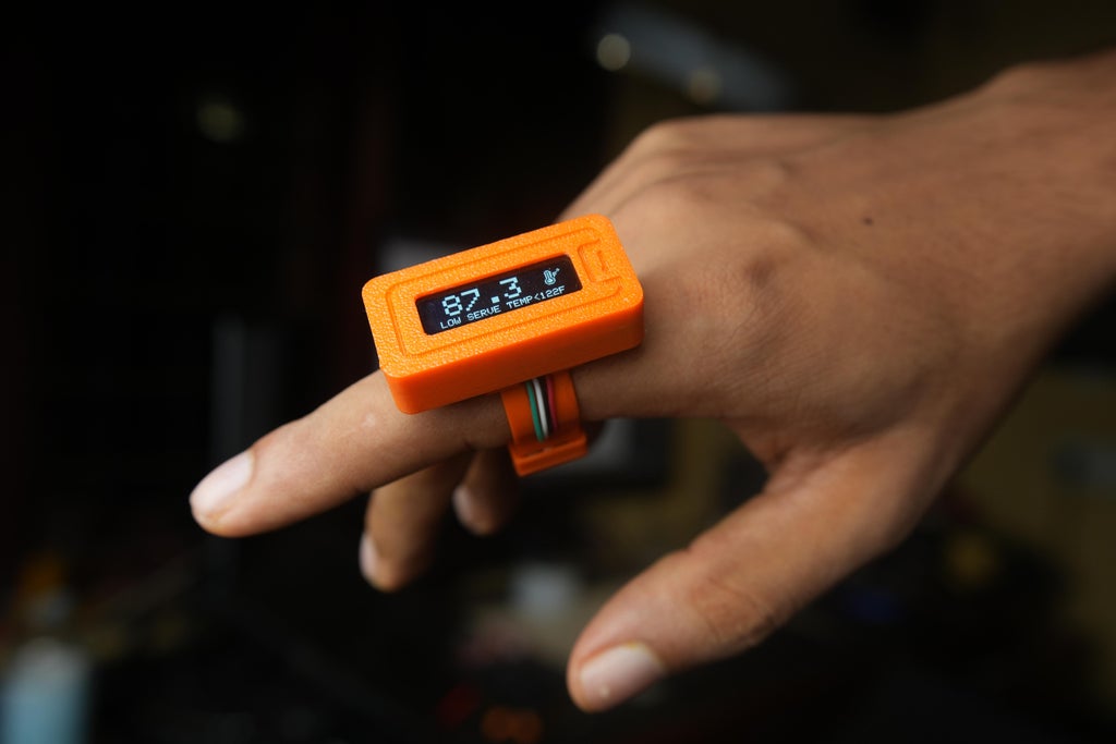
As the name suggests it is an infrared thermometer that can be worn like a ring on the finger. The thermometer has an infrared temperature sensor under the ring, and the temperature reading is displayed on an OLED screen on top of the ring. For this project, I used the Xiao esp32c3 microcontroller, and I incorporated a built-in BMS for recharging the battery. Additionally, I used the MLX90614 Non-Contact Precision Thermometer Module, which provides fast temperature readings ranging from -70°C (-94°F) to +380°C (+720°F).The sensor does not need to have contact with the subject to measure the temperature. You can get a reliable measurement from 2cm to 5cm away from the subject.
I thought this would be useful for restaurant or food truck workers. With this setup, the worker can still take readings while handling food or drinks for the customer. No need to grab another thermometer and use it. This can save time on the order because the worker can do other tasks while wearing this. It is a great use case for this project
This tool can be customized by changing a few lines of code. For example, you can pre-set different temperature values or ranges and display a message if the sensor reaches these readings. This customization can be helpful for various purposes like baby food motoring, baking, scientific analysis, manufacturing, etc. I can guide you on how to edit the program to fit your specific needs in Step 3
so let's start the build
Note: Please wait a moment for all the GIFs on the web page to load.
Supplies
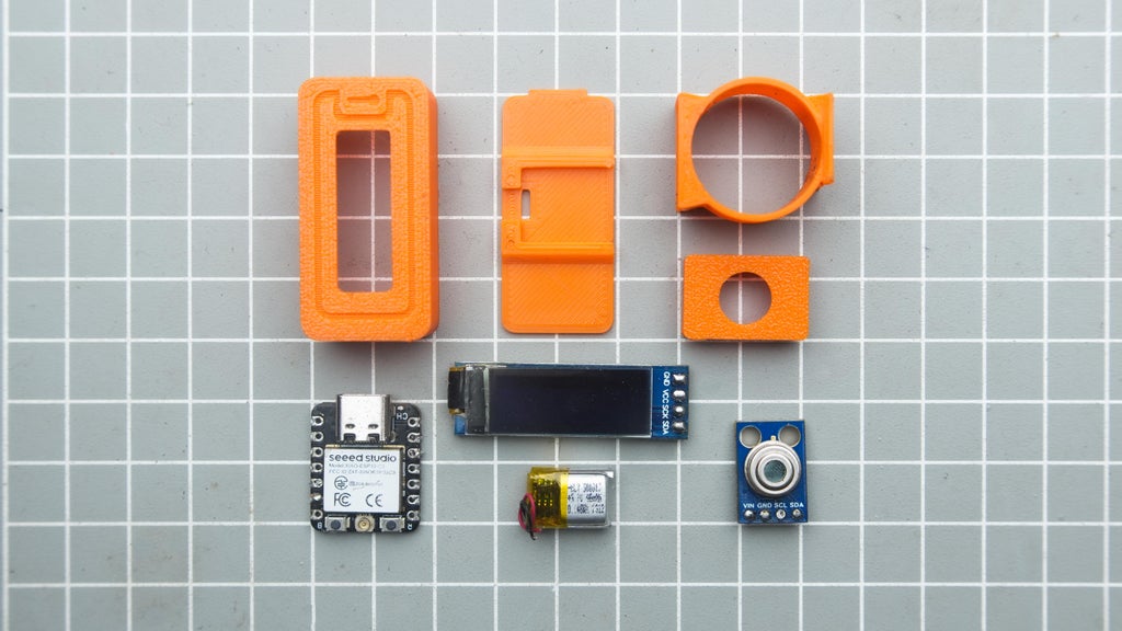
Things You Need
Click the part name to open the purchase link (Just experimenting with new ways of presenting)


Tools used
- Soldering kit
- Soldering helping hand
- Tweezer
- Wire cutter
- Utility knife
- 3d printer
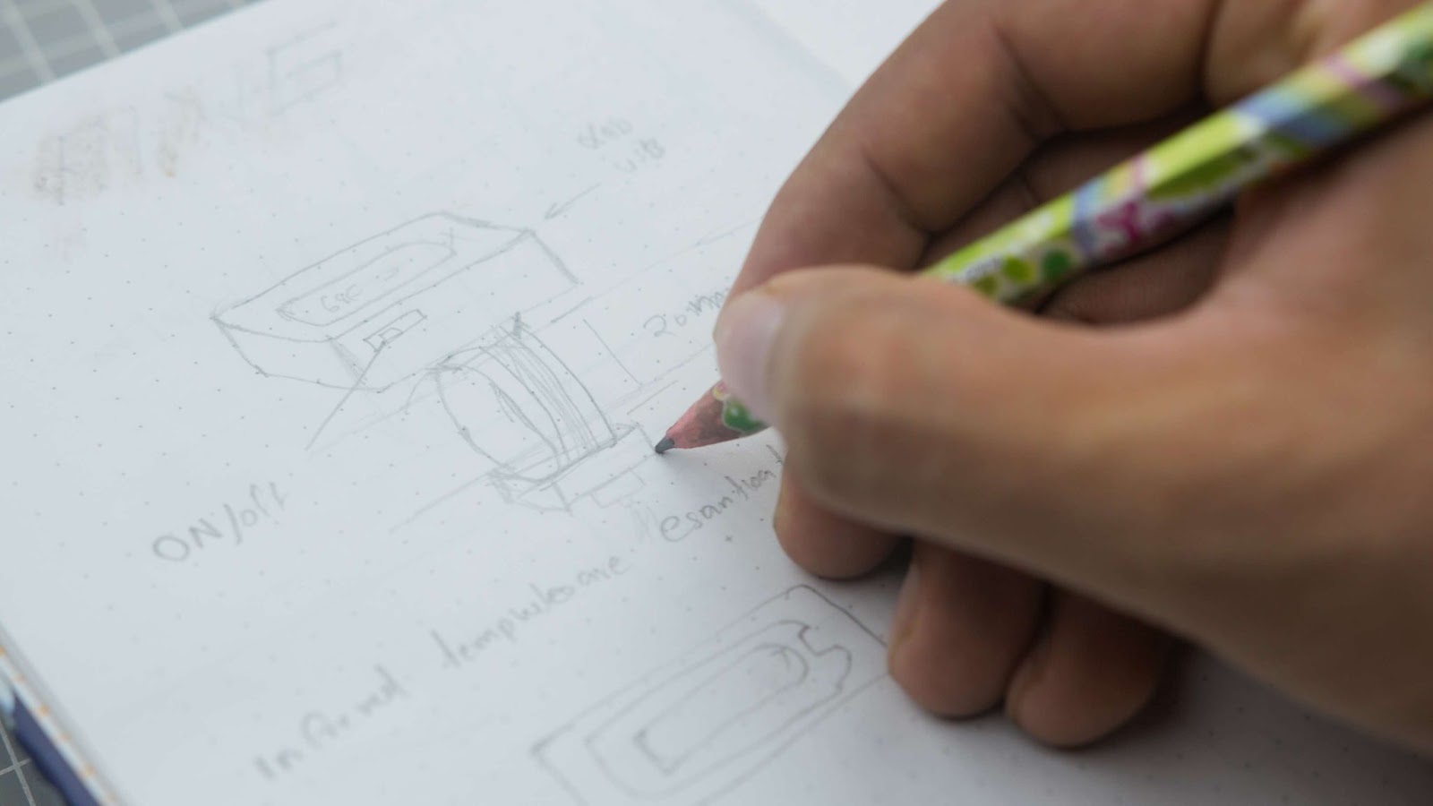
Step1:Idea to Reality
Initially, I created a preliminary sketch of the project to visualize its appearance.
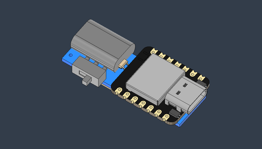
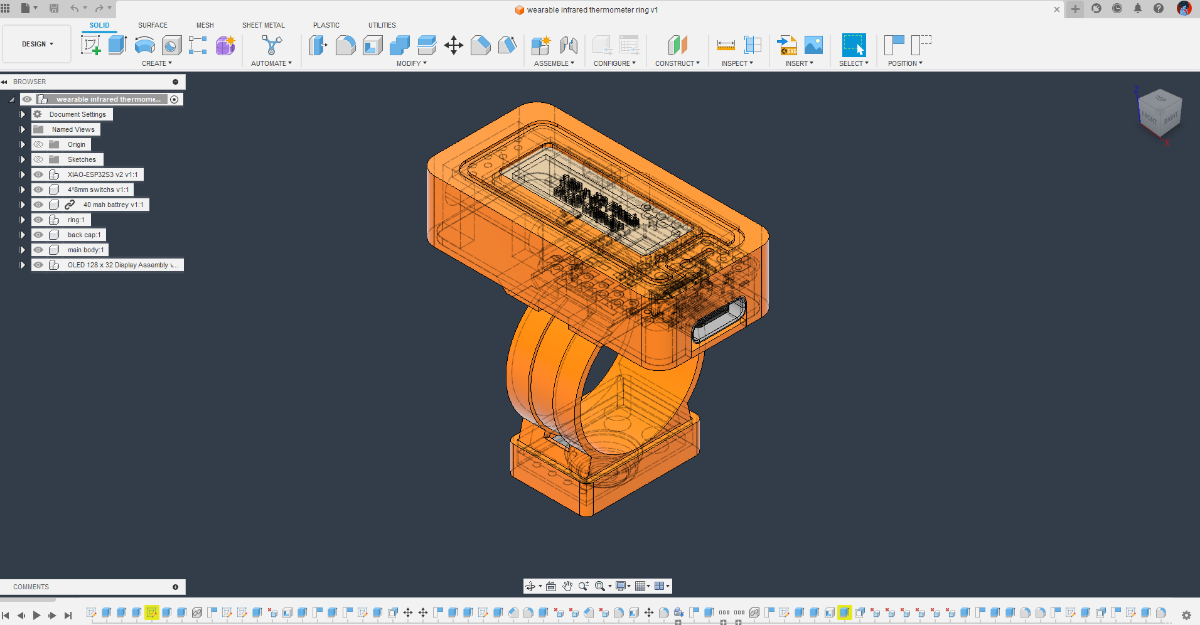
Then I used Autodesk Fusion 360 to design this project. I started by importing the 3d model of each component and moved them around to get them in close as possible. also, it needs to be easy to assemble.
After finding a good configuration, I built the enclosure around it. Also, my ring size is 20mm. I designed the ring part with this measurement
.Step and .f3z 3D design files are attached to this project
Step 2: 3D Printing
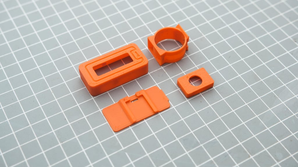
used my Anycubic Kobra to 3D print all the files. I printed them in PLA+. I also designed all the parts with 3D printing in mind, so none of the parts are challenging to 3D print. You can find the STL files attached in this step
.STL files are attached to this project
Step 3: Customizing the Code
As an example, we will configure it to find the right serving temperature for the food item
The parameters we need are as follows:
- If the measured food temperature is lower than 122F, we need to display a "Low serve temperature" warning.
- If it is between 122F and 140F, we need to show a "Good serve temperature" message.
- If it is higher than 140F, we need to display a "High serve temperature" warning.
Now let's look at how to modify the code to achieve our speciation
To set the low temperature
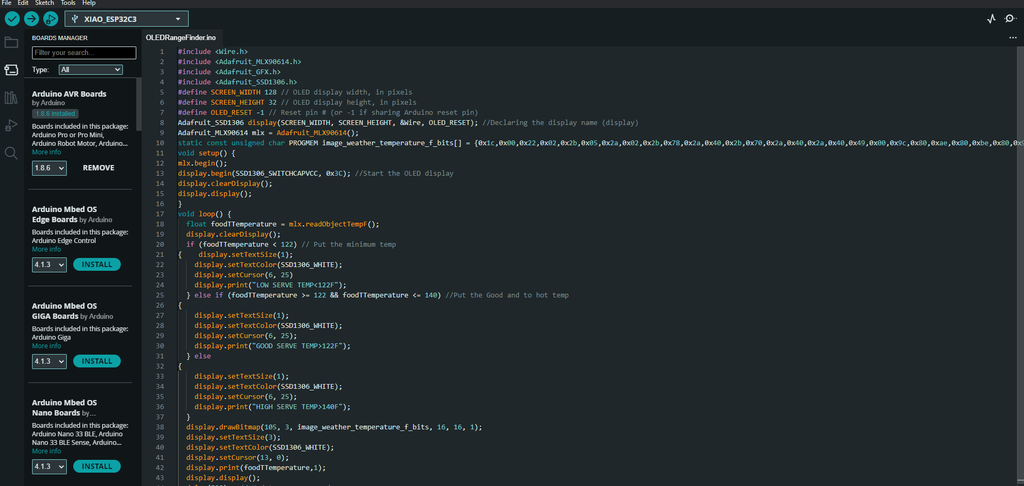
Edit the value in the line number 20
if (foodTTemperature < 122) // Put the minimum tempAlso, the message that needs to be displayed can be added in line number 24
display.print("LOW SERVE TEMP<122F");To set a good temperature range
Edit the value in the line number 25
else if (foodTTemperature >= 122 && foodTTemperature <= 140)Also, the message that needs to be displayed can be added in line number 30
display.print("GOOD SERVE TEMP>122F");To set the high temperature
If the value range configured in line number 25 surpasses 140F we can display the message through line number 36
display.print("HIGH SERVE TEMP>140F");Here is the completed code for a quick look. I attached this.ino file in this step
I also include a Celsius version of it Infrared_Temp_Ring_C_Food.ino
full code
#include <Wire.h>
#include <Adafruit_MLX90614.h>
#include <Adafruit_GFX.h>
#include <Adafruit_SSD1306.h>
#define SCREEN_WIDTH 128 // OLED display width, in pixels
#define SCREEN_HEIGHT 32 // OLED display height, in pixels
#define OLED_RESET -1 // Reset pin # (or -1 if sharing Arduino reset pin)
Adafruit_SSD1306 display(SCREEN_WIDTH, SCREEN_HEIGHT, &Wire, OLED_RESET); //Declaring the display name (display)
Adafruit_MLX90614 mlx = Adafruit_MLX90614();
static const unsigned char PROGMEM image_weather_temperature_f_bits[] = {0x1c,0x00,0x22,0x02,0x2b,0x05,0x2a,0x02,0x2b,0x78,0x2a,0x40,0x2b,0x70,0x2a,0x40,0x2a,0x40,0x49,0x00,0x9c,0x80,0xae,0x80,0xbe,0x80,0x9c,0x80,0x41,0x00,0x3e,0x00};
void setup() {
mlx.begin();
display.begin(SSD1306_SWITCHCAPVCC, 0x3C); //Start the OLED display
display.clearDisplay();
display.display();
}
void loop() {
  float foodTTemperature = mlx.readObjectTempF();
  display.clearDisplay();
  if (foodTTemperature < 122) // Put the minimum temp
{    display.setTextSize(1);
    display.setTextColor(SSD1306_WHITE);
    display.setCursor(6, 25);
    display.print("LOW SERVE TEMP<122F");
  } else if (foodTTemperature >= 122 && foodTTemperature <= 140) //Put the Good and to hot temp
{
    display.setTextSize(1);
    display.setTextColor(SSD1306_WHITE);
    display.setCursor(6, 25);
    display.print("GOOD SERVE TEMP>122F");
  } else
{
    display.setTextSize(1);
    display.setTextColor(SSD1306_WHITE);
    display.setCursor(6, 25);
    display.print("HIGH SERVE TEMP>140F");
  }
  display.drawBitmap(105, 3, image_weather_temperature_f_bits, 16, 16, 1);
  display.setTextSize(3);
  display.setTextColor(SSD1306_WHITE);
  display.setCursor(13, 0);
  display.print(foodTTemperature,1);
  display.display();
  delay(500);  // Update every second
}
Step 4: Uploading Code to XIAO ESP32C3
I always like to upload the code to the microcontroller before assembly. I am using Arduino IDE to flash the code. follow these tutorials for setting up IDE for Seeed Studio XIAO esp32c3 and learn more about this board
Please download and install the Adafruit_MLX90614.h library before compiling
How to install library tutorial video link
After this, I connected Xiao to a USB and flashed the program
Step 5: Wiring Diagram
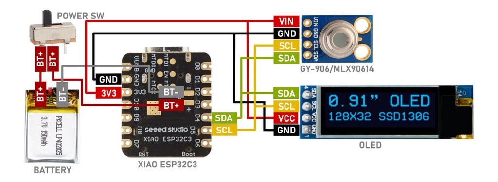
it is a simple circuit
- D4 of xiao to SDA of OLED and GY-906
- D5 of xiao to SCL of OLED and GY-906
- 3v3 of xiao to VCC of OLED and GY-906
- GND of xiao to GND of OLED and GY-906
Step 6: Why Glue ?
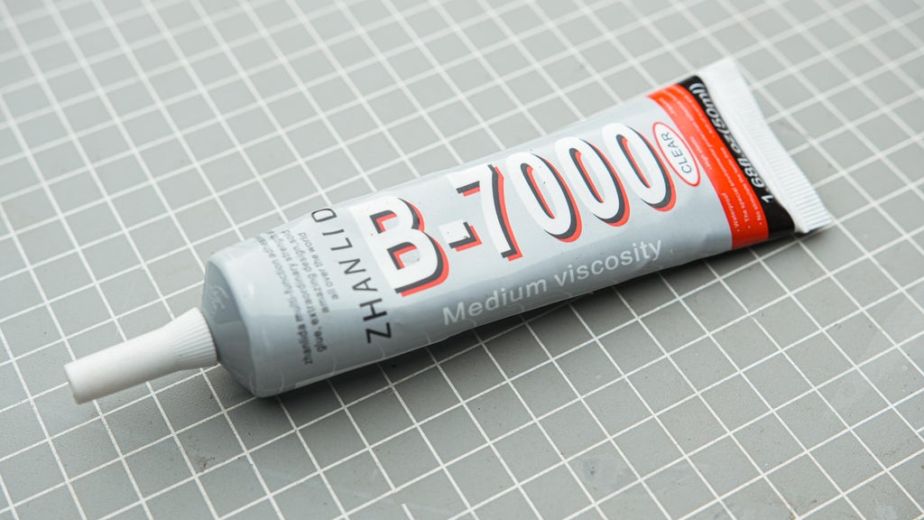
Due to the small size of our project, we need to use a different approach for assembly. Since we don't have any screw holes on the parts, we can't use tiny screws to hold everything together. The best method to use is glue, which is the same manufacturing method used in most compact tech products like the AirPods, for example. We are not using hot glue here but a B-7000 multi-purpose glue. Now let's start the assembly.
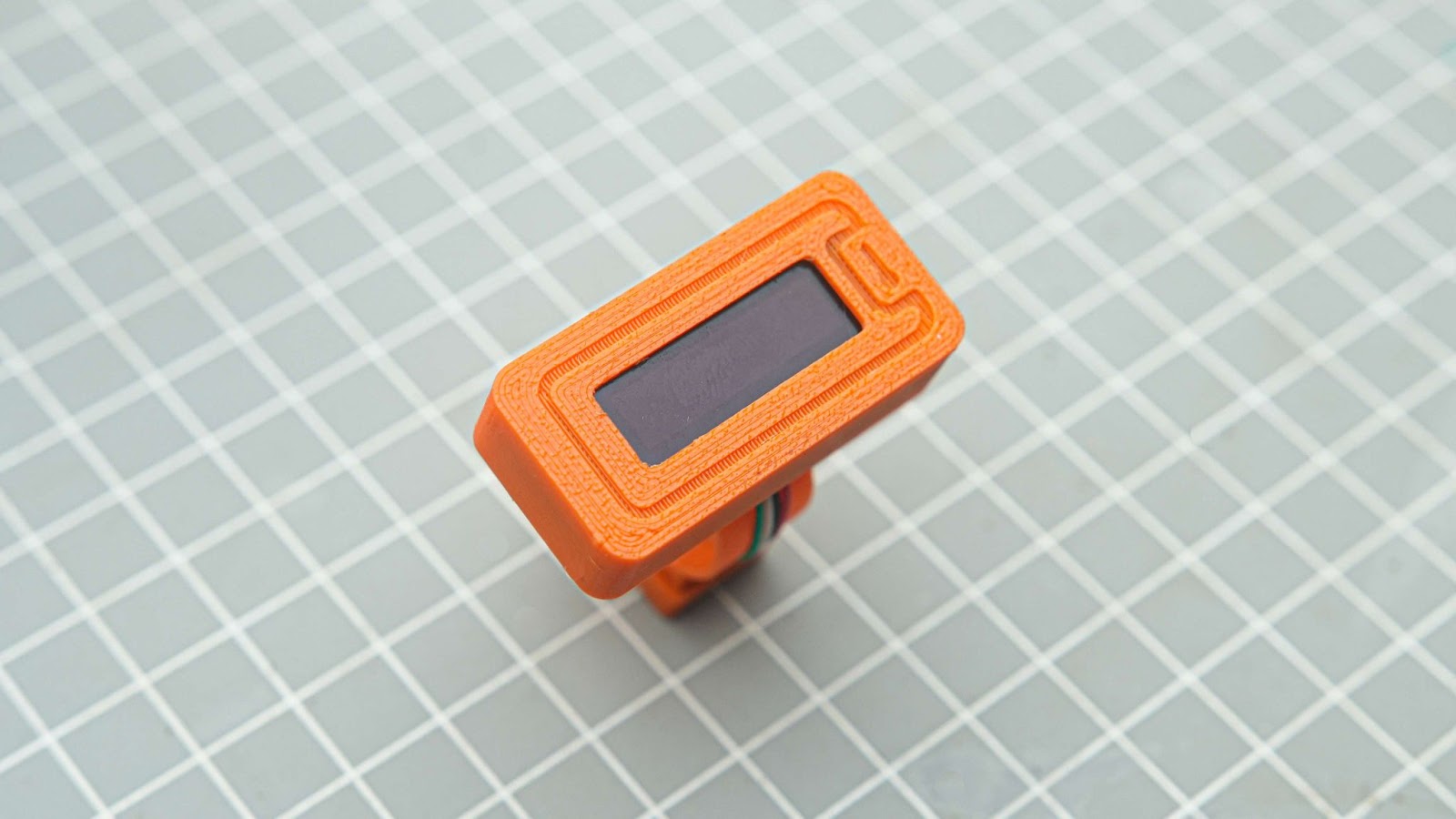
Step 7: OLED Display
We can start the assembly by soldering 4 wires on the back side of the OLED display
1. GND, VCC, SCK, SDA. Using different color-coded wires makes wiring easier. It helps us remember the correct wiring connections.
2. Now push the screen into the 3d print.
3. apply some glue on the sides of the display
4. Use some Kapton tape to isolate all exposed contacts on display pcb
Step 8: Battery and Power Switch
1. Trim the switch terminals using a wire cutter.
2. Solder the battery +Ve wire to one of the switch terminals. Additionally, solder a small wire from the other terminal of the switch
3. Now place the switch into 3d 3D-printed slot and glue it
4. Apply some glue to the battery and place it on top of the display PCB
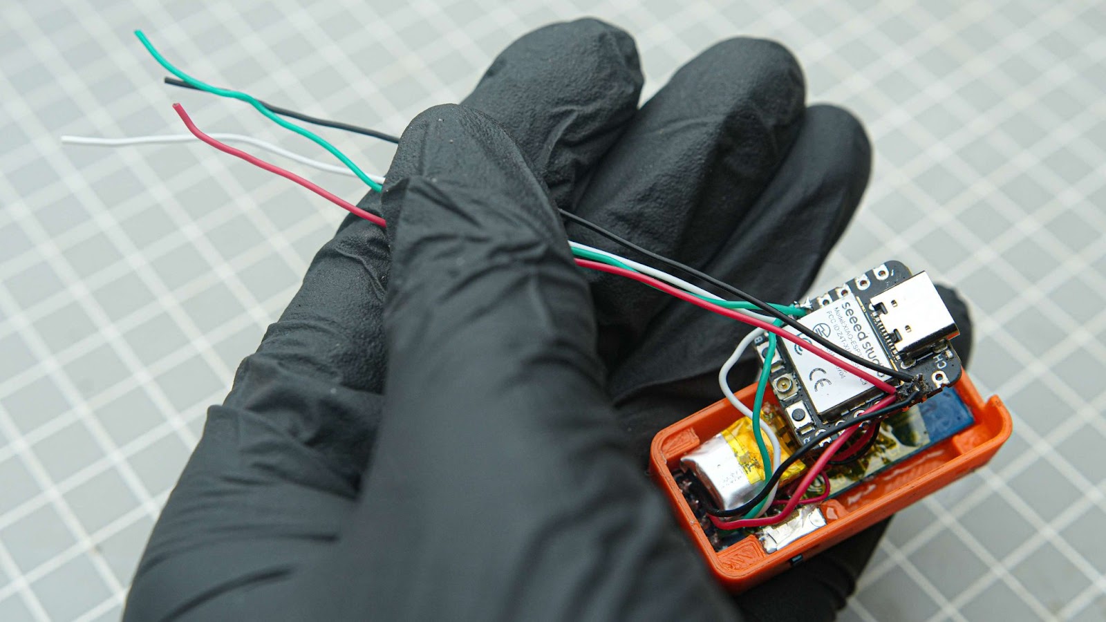
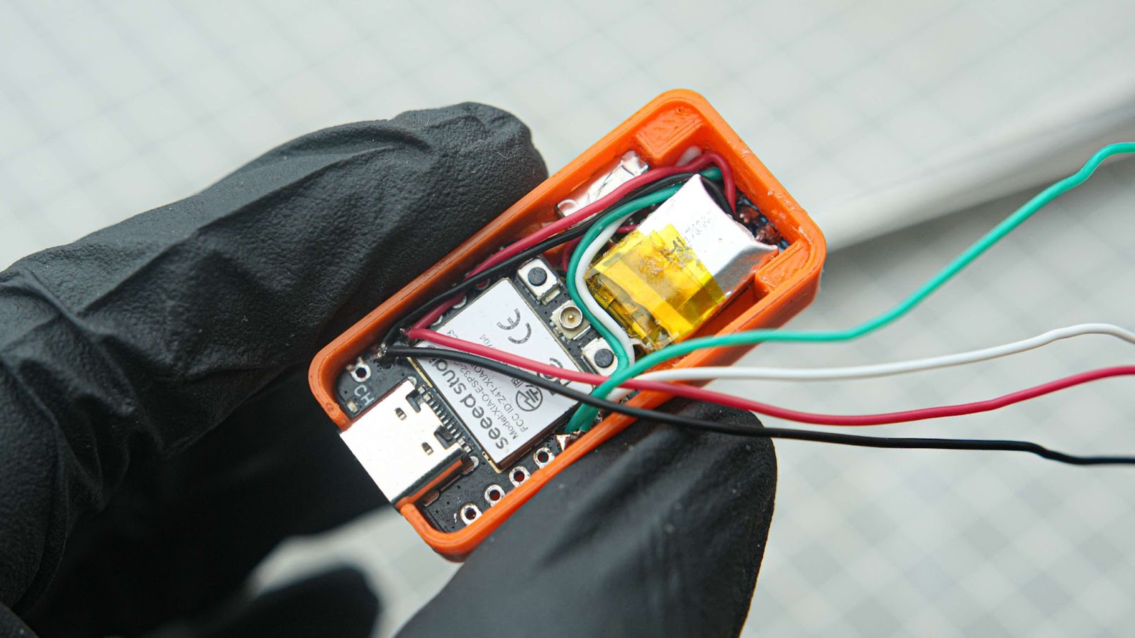
Step 9: Wiring XIAO ESP32C3
Next, we should solder the wire connections to the Xiao board following the circuit diagram provided in Step 5. I utilized a helping hand to secure the Xiao in position for easier soldering.
1. soldered the battery power and switch wire into XIAO ESP32C3
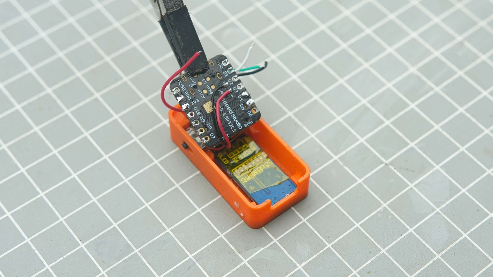
2.Next solder the OLED wires into XIAO
3.Now, cut four wires and solder them into the xiao GPIO pins - 3v3, GND, SDA, SCL. These wires will be used to connect the temperature sensor.
4.Insert the xiao into the 3d printed body and glue it
5.I did some wire management with my Tweezer
6.Now, run the four wires through the small gap in the back cap.
7.Apply some glue on the edges of the back cap
8.And close the back cap
Step 10: Adding Temperature Sensor and Ring
1. Slide the ring into the slot on the back cap
2. Now run wire through the gap on the ring
3. Cut and solder these 4 wires into the sensor. I used a helping hand to hold the sensor board
4. Now use the sensor cap to hold the sensor into the ring. This will snape fit without the glue
5. Yes we just completed the assembly
Step 11: Power It on and Test It !!
You can power on the device using a switch on the side. No calibration is needed as the device is factory-calibrated and precise. you can recharge the battery through the USB port of Xiao, Make sure that the device is powered on during charging. there will be a red LED near the USB port which indicates the the battery is charging.
Final Thought
I hope this project can help you complete your tasks more efficiently. There are numerous possibilities for this project - you can easily edit it and add custom functions to your application. If you need any help, let me know in the comments or just send me a dm.