


Story
Opportunities
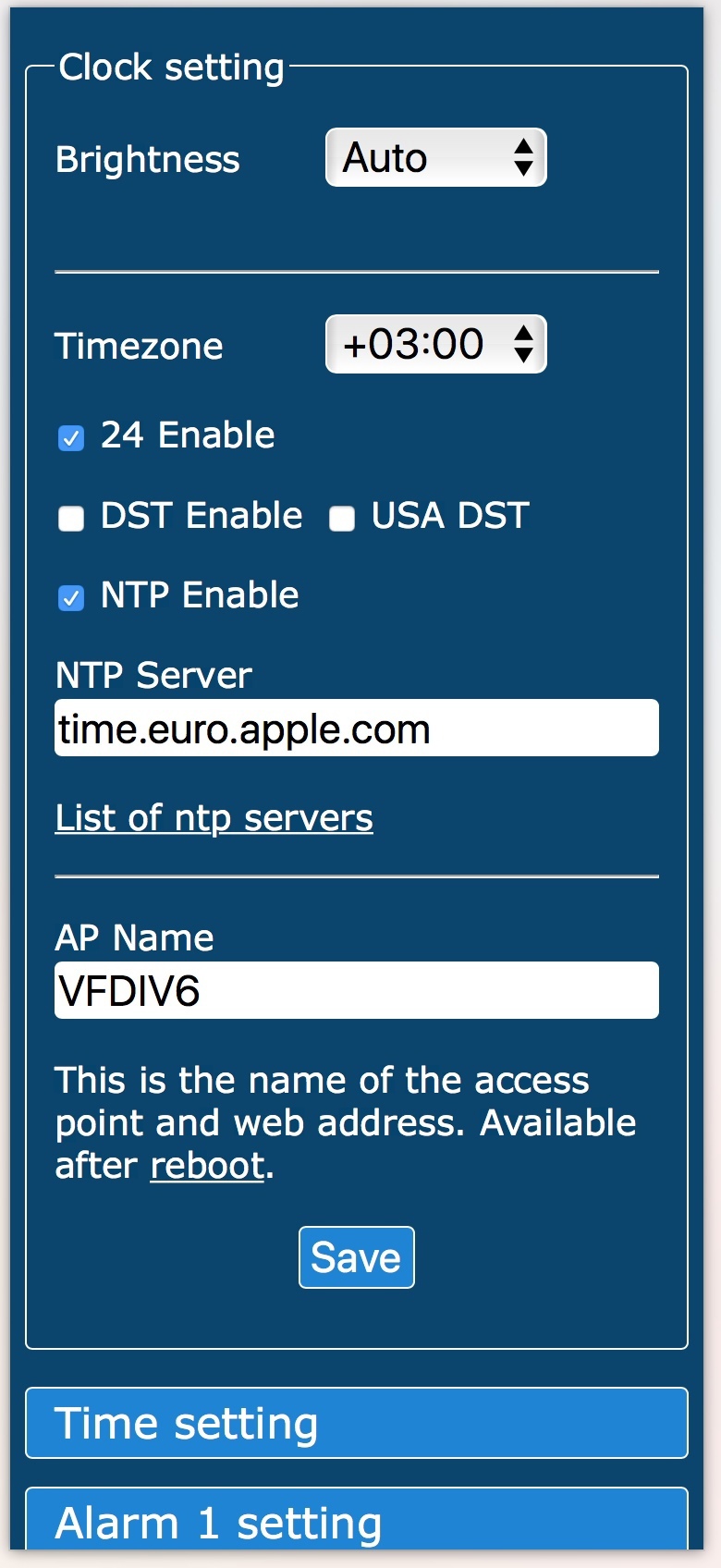
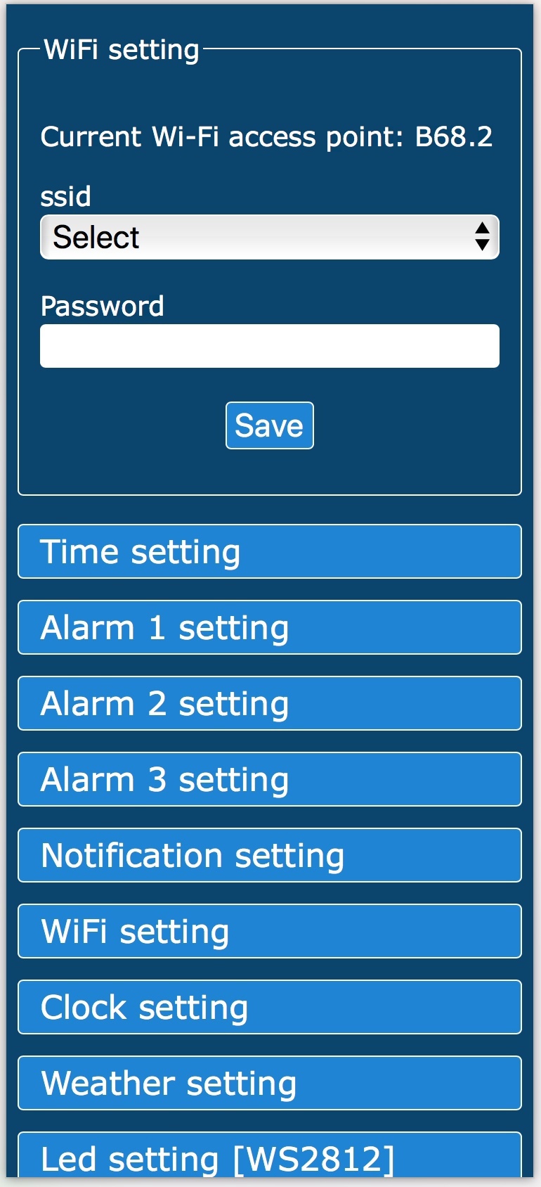
- Automatic setting and synchronization of the exact time when connected to the network.
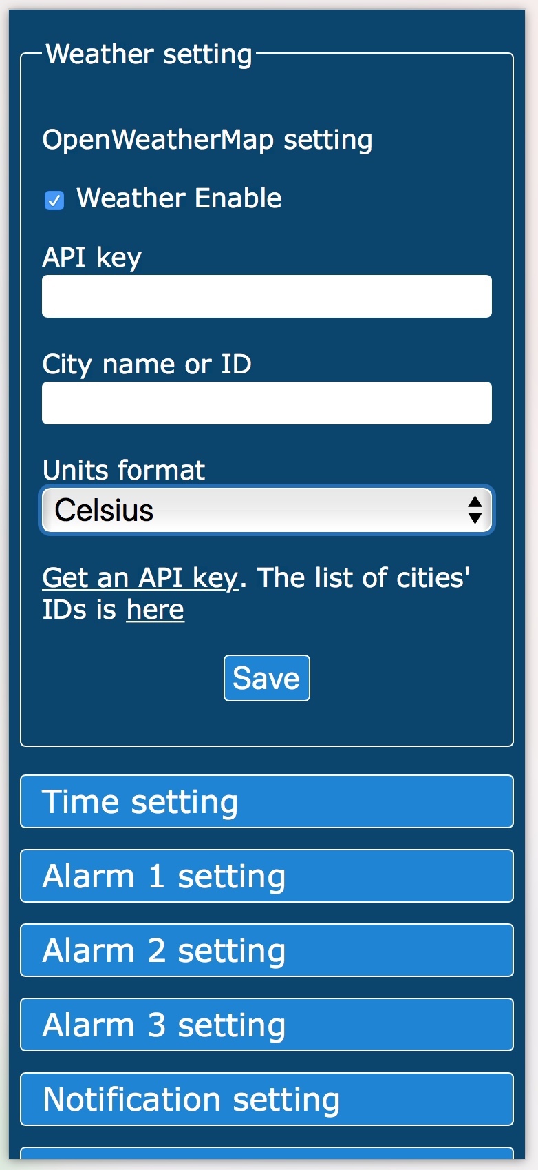
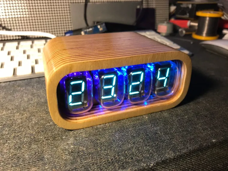
- Getting weather information from the OpenWeatherMap service and cyclically displaying the temperature every 15 seconds
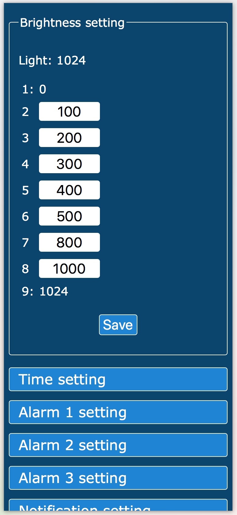
- Manual or automatic adjustment of the brightness of the indicators and LEDs depending on the illumination.
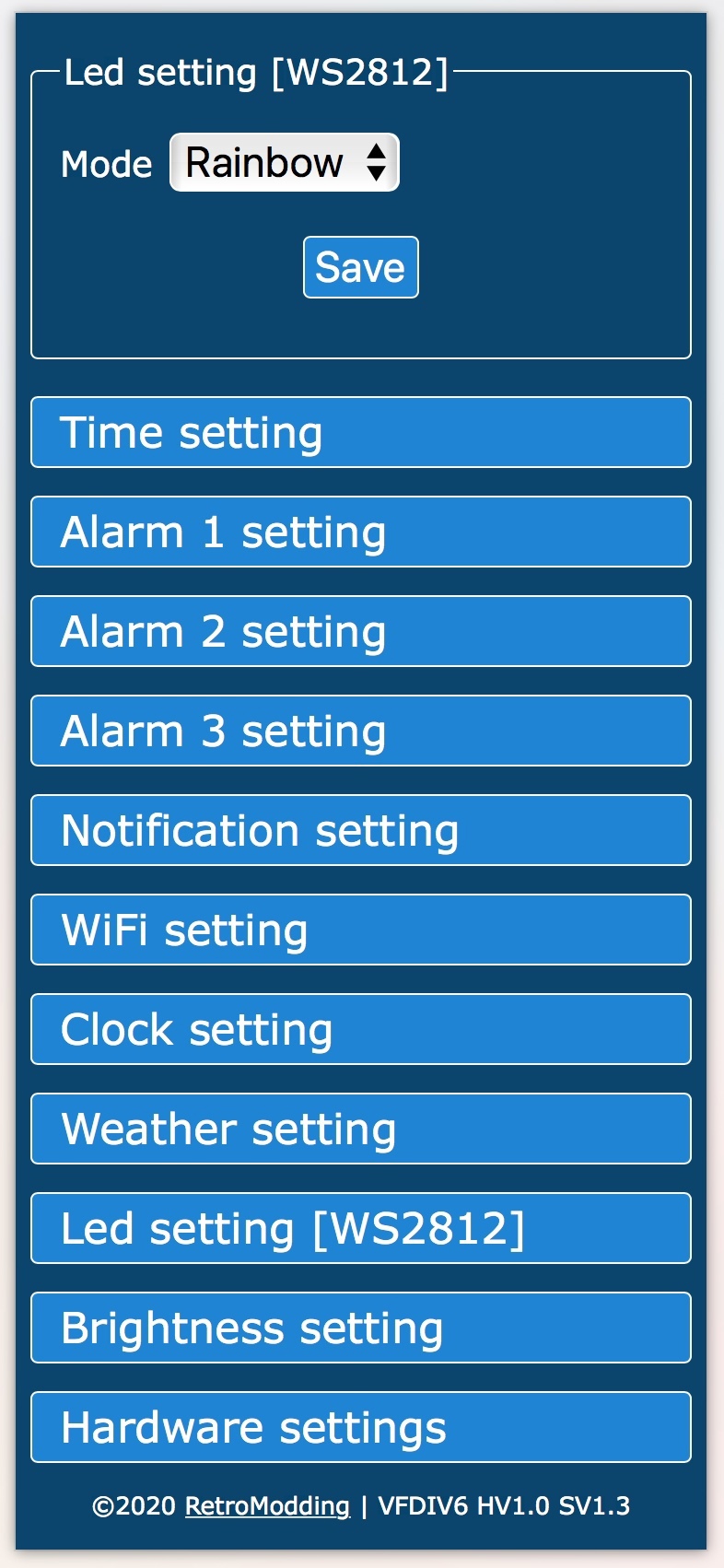
- The ability to control 12 SW2812 LEDs, supports 3 modes static, rainbow and seconds
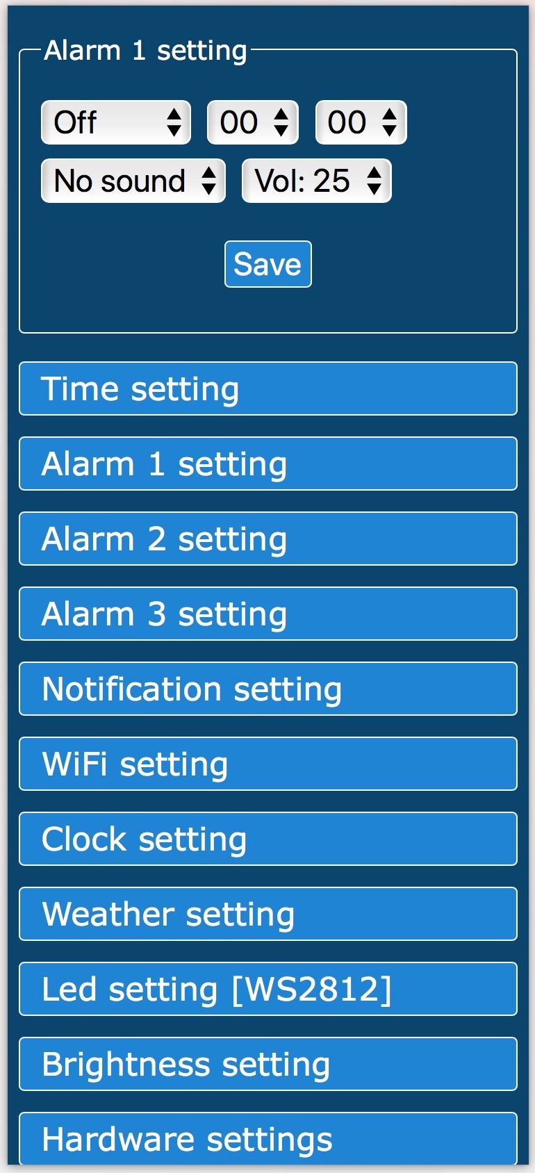
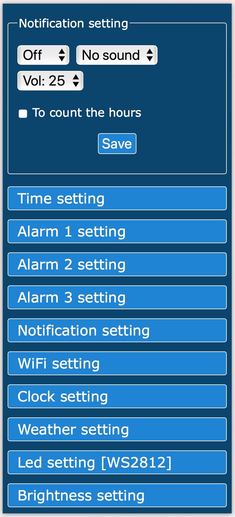
- Management and configuration via the web interface.
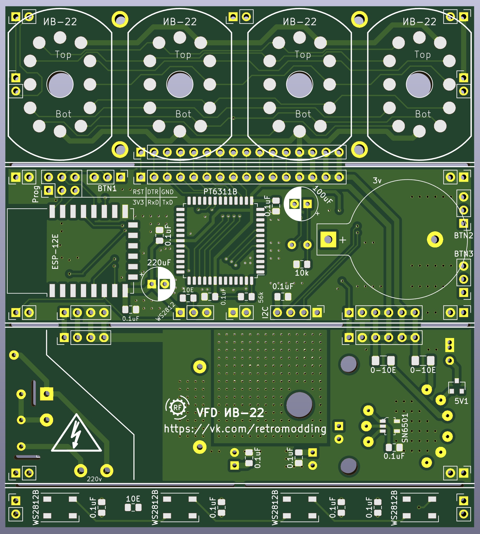
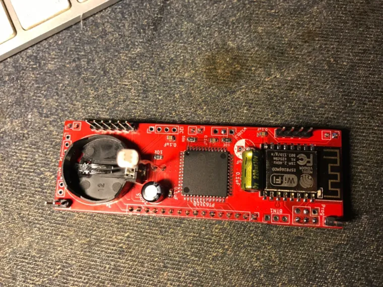
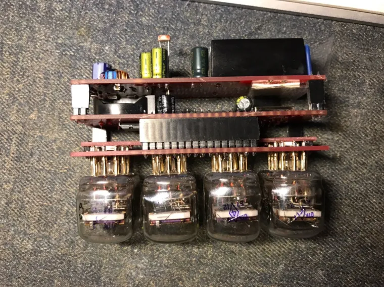
The watch is assembled on the ESP12E module(ESP8266). Using this module allows you to implement time synchronization using the NTP protocol and manage clock settings through a browser.
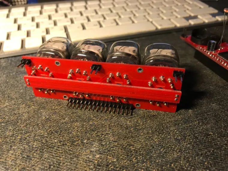
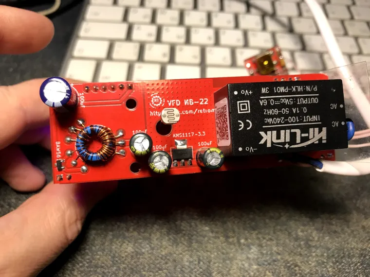
A special PT6311B driver is used to control the indicators, which provides dynamic display functions and brightness adjustment.
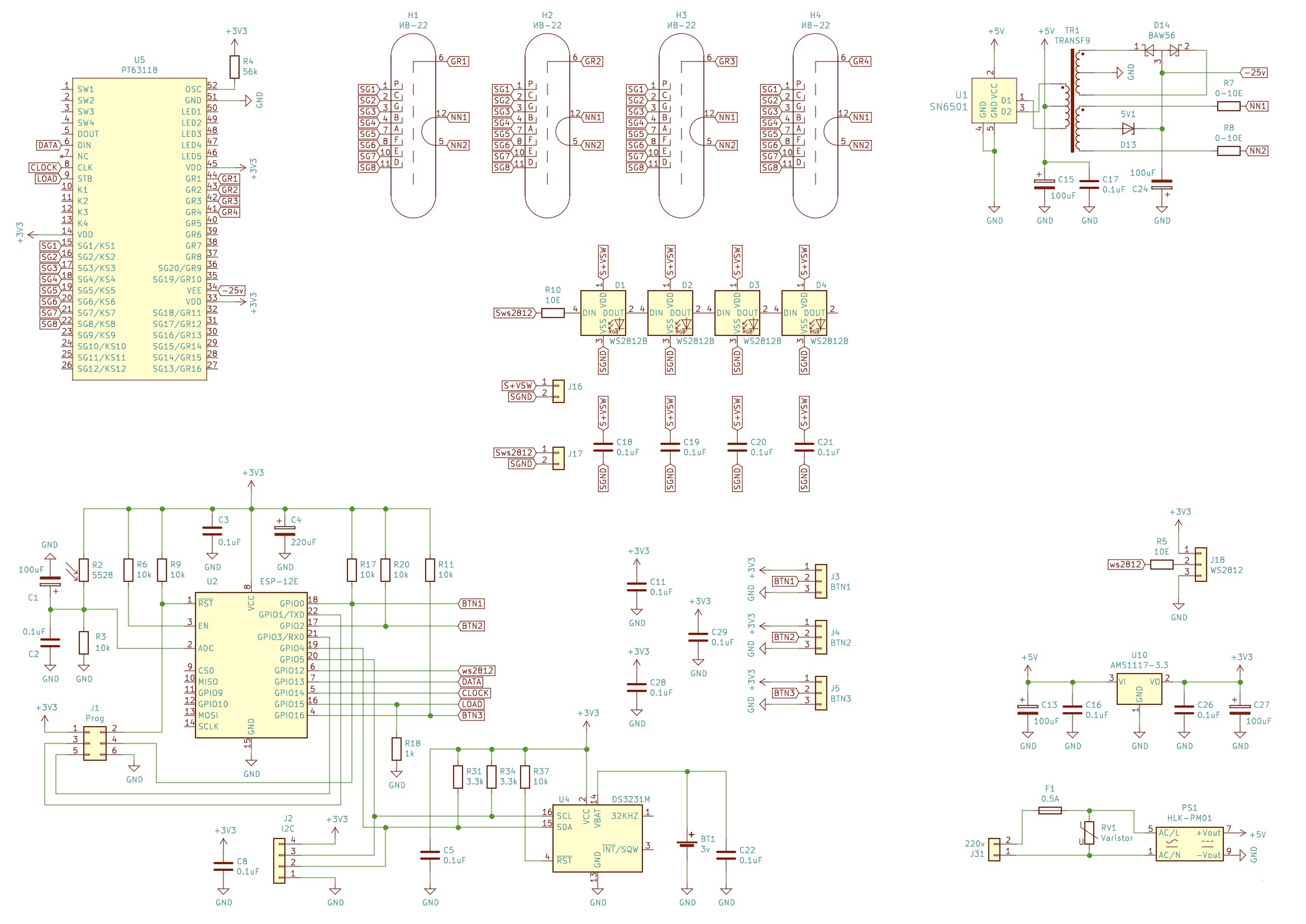
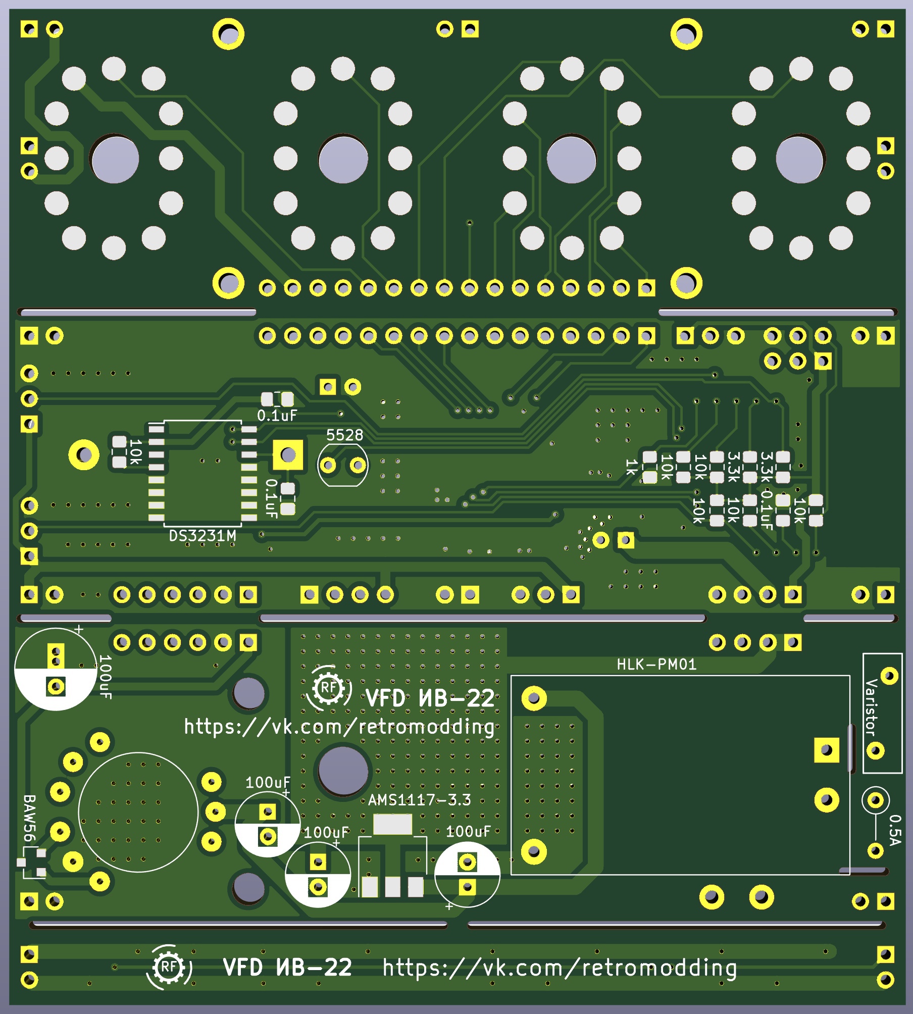
The glow supply of the indicators and the anode/grid voltage are generated by the converter on the SN6501. The AMS1117-3.3 by 3.3 volt linear stabilizer is used to power the watch.
The DS3231 is used as a real-time clock. Which has a separate backup power supply to keep the clock running in the absence of the main power supply. The current consumption of the clock does not exceed 300 milliamps and depends on the brightness of the indicators and the operating mode.
A photoresistor is used as a light sensor.
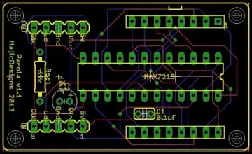
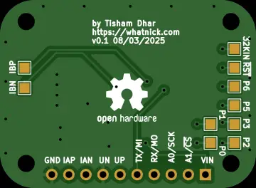
The board has connectors for connecting 3 buttons, an i2c bus, additional WS2812 LEDs and programming the ESP-12 module.
The connectors for the buttons have an additional power output, which allows you to use touch modules instead of buttons. Currently, only one BUTTON1 button has software support, when you click on it, the date is displayed. It is also possible to use these connectors for the 1-Wire bus.
The i2c bus is designed to connect additional sensors, temperature, humidity, pressure, etc.
The Prog connector is designed for the initial firmware of the ESP-12 module, as well as for connecting the DFPlayer mini mp3 module (this module is necessary for alarm operation). The module is connected as follows:
ESP -> DFP
+3.3V -> VCC (1)
TxD -> RX (2)
RxD -> TX (3)
GND -> GND (7)
Four WS2812 LEDs are connected to the board to illuminate the indicators. The LED control is connected in parallel to the WS2812 connector, 12 more LEDs can be connected to the connector itself, it is better to power these LEDs from a separate 3.3v source
The filament winding outputs about 1.7v, which is quite a lot for the applied indicators, so we extinguish the excess voltage with two resistors. The conversion frequency is about 400 kHz, it will not work to measure the voltage of such a frequency with a conventional tester, you need a special voltmeter or oscilloscope with the ability to measure the RMS voltage value. The resistance of the resistors is 0.38 ohms. It is quite difficult to find a resistor for such a resistance, so you can put the nearest nominal value in the range of 0.33-0.47 ohms, also the required nominal value can be assembled from several parallel resistors, for example, by connecting 3 1.2 ohm resistors in parallel, we get 0.4 ohms
The transformer is wound on a ring B64290L0038X087, N87, R10x6.x4, in theory any ring made of ferrite of the appropriate size, with an initial permeability of 2200, the primary winding contains 2x6 turns with a 0.4mm wire, the secondary 2x35 turns with a 0.1mm wire and an incandescent 2x1 turn with a 0.4mm wire. First, we wind 35 turns into two 0.1 mm wires, try to evenly distribute the turns throughout the coil, then we wind 6 turns with a 0.4 mm wire and 6 more turns, the same with an incandescent winding, in the end it should turn out something like in my photo.