Story
Long before the Heathkit 6800 microcomputer learning system, the Arduino Uno, or the Basic Stamp, there was Radio Shack’s Science Fair Microcomputer Trainer kit. Introduced in 1985, this easy-to-program kit was intended to teach users how microcomputers worked.
In this project article, we’ll upgrade this vintage microcomputer by building and adding an adjustable Raspberry Pi Pico clock with an LED display. After assembling the hardware, we’ll program the trainer to operate as a 7-bit binary counter. Before any of that, though, let’s spend some time learning about the trainer’s features—and, in particular, about the TMS1100 microcontroller at its core.
The Radio Shack Science Fair Microcomputer Trainer Kit
The Science Fair Microcomputer Trainer first appeared in Radio Shack’s 1985 catalog (Figure 1).

Figure 1. The introduction of the Science Fair Microcomputer Trainer in the 1985 Radio Shack catalog. Image used courtesy of RadioShackCatalogs
The kit, which is built around a Texas Instruments TMS1100 microcontroller, has the following input/output (I/O) features:
- A keyboard.
- A 7-segment LED display.
- Seven discrete LEDs.
- An audio amplifier.
- An 8 Ω speaker.
- A 400 kHz clock.
The Microcomputer Trainer has a 9 VDC operating voltage, which is supplied by six AA batteries inserted into a compartment at its bottom. The keyboard, which is visible in Figure 2, is configured as hexadecimal. It combines numbers and letters for memory addressing and programming the TMS1100 microcontroller.

Figure 2. The Microcomputer Trainer’s hexadecimal keyboard. Image used courtesy of Don Wilcher
The TMS1100 Microcontroller
The TMS1100 microcontroller is part of the TMS 1000 family of 4-bit microcomputer integrated circuits. The TMS1100 used PMOS technology and was introduced by Texas Instruments in 1975. At the time, the TMS1100’s single-chip, binary, microcomputer architecture was unique, and it was marketed as the first system-on-chip microcomputer.
The TMS1100 includes ROM, RAM, and an Arithmetic Logic Unit (ALU). The microcontroller architecture can be seen in Figure 3.

Figure 3. TMS1100 microcontroller architecture. Image used courtesy of Bitsavers
The physical interface to the TMS1100 consists of a basic input/output structure. Input pins are designated by the letter K, and outputs by either O or R.
- The K-inputs manage 4 bits of data and are binary weighted: K1, K2, K4, K8. Data is retrieved from these weighted input pins.
- There are eight parallel O-outputs, numbered O0 through O7. These outputs are latching-capable. They typically display binary data on discrete LEDs or 7-segment displays.
- Eleven output pins are represented by the letter R. The R-outputs multiplex the K-inputs and strobe the O-output data to displays and internal memory registers.
The TMS1100 is a 4-bit processor. The ROM is 16,384 bits configured as 2,048 8-bit words. The RAM is 512 bits arranged as 128 4-bit data words.
Programming the Microcomputer Trainer
Programs for the Microcomputer Trainer are based on the machine code for the TMS1100. The kit’s machine code aligns with 32 commands, allowing the vintage microcomputer kit to perform operations such as:
- Arithmetic.
- Data storage.
- Memory display.
- Manipulation of address information.
Games, electronic timers, sound effects, and arithmetic calculators can be programmed on the microcomputer in this way.
Included with the kit is a lab manual with 100 programming exercises and activities. The initial lab exercises focus on wiring and testing the audio amplifier and the microcontroller’s I/O ports. The manual is shown in Figure 4.

Figure 4. Microcomputer Trainer lab manual. Image used courtesy of Don Wilcher
Project Concept and Operation
Our project begins with one of the basic programming tasks introduced in the lab kit manual: transferring data into the A-register. The Transfer Into A (TIA) command, which is machine code 8, is initiated by pressing the 8 key. Pressing the Increment key finalizes the data transfer.
When we press the Increment key, the kit’s seven discrete LEDs count in binary. This manual binary counting event, which is unique to the Microcomputer Trainer, can easily be automated using a digital clock or oscillator. In this project, we’ll automate this task using four electronic parts:
- A Raspberry Pi Pico.
- A 10 kΩ potentiometer.
- A 4-digit 7-segment LED module.
- A transistor relay module.
Together, these will make up an adjustable digital clock with an LED display. Figure 5 shows how the four parts will work together.

Figure 5. Project concept block diagram. Image used courtesy of Don Wilcher
The Raspberry Pi Pico will produce the on/off control pulses that drive the transistor relay module’s Single Pole Double Pole (SPDT) contacts. The transistor relay module contact speed can be adjusted from 135 ms to approximately 8 seconds by adjusting the 10 kὨ potentiometer. The adjusted time will be visible on the 4-digit 7-segment LED display.
With that, let’s start our build.
The Adjustable Digital Clock Build
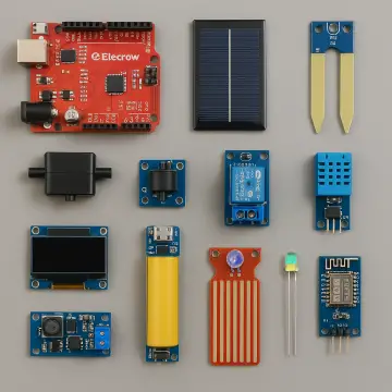
Building the adjustable digital clock requires wiring the project concept parts on a solderless breadboard. The Elecrow Raspberry Pi Pico Advanced Kit (Figure 6) provides several parts we’ll need, including:
- 10 kΩ potentiometer.
- Raspberry Pi Pico.
- 4-digit 7-segment LED display module.
- Jumper wires.
- Solderless breadboards.

Figure 6. Elecrow Raspberry Pi Pico Advanced Kit. Image used courtesy of Elecrow
The project build also requires a transistor relay module. The Raspberry Pi Pico’s VSYS pin, which will power the electromechanical relay coil, provides 5 VDC. We’ll therefore use a 5 VDC module. The Raspberry Pi Pico’s GPIO2 pin will provide the on/off control signal to the surface mount device (SMD) transistor on the PCB.
The electrical wiring diagram in Figure 7 shows the four components of the clock inserted into a solderless breadboard.

Figure 7. Electrical wiring diagram for the adjustable digital clock with LED display. Image used courtesy of Don Wilcher
Figure 8 provides the circuit schematic as an additional build support reference.

Figure 8. Circuit schematic for the adjustable digital clock with LED display. Image used courtesy of Don Wilcher
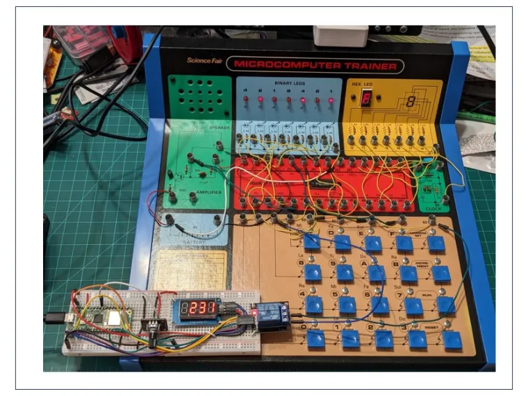
The final build of the digital clock is shown in Figure 9.

Figure 9. The assembled digital clock and LED display. Image used courtesy of Don Wilcher
This adjustable digital clock circuit needs to provide a clean switching pulse of variable width. To test this, an oscilloscope was attached to GPIO2 of the Raspberry Pi Pico so that it could observe the control switching pulses. The oscilloscope measured an output switching pulse voltage of 3.38 V (Figure 10).

Figure 10. Captured output control pulse from the Raspberry Pi Pico GPIO2 pin. Image used courtesy of Don Wilcher
Connecting the Raspberry Pi Circuit to the Microcomputer Trainer
The final hardware assembly (Figure 11) consists of wiring the transistor relay module’s Normally Open (NO) contacts to spring terminals 57 and 63 on the microcomputer kit.

Figure 11. The assembled digital clock connected to the Microcomputer Trainer. Image used courtesy of Don Wilcher
Software Build
I used MicroPython to build software for the adjustable digital clock. Some of the code is shown below:
This software, which can either be initiated in debug mode or saved onto the Raspberry Pi Pico, enables three functional aspects:
- Reading the adjusted analog voltages produced by the 10 kΩ potentiometer.
- Displaying the values on the 4-digit 7-segment LED module.
- Switching the transistor relay module.
We can change the desired switching time for sequencing the microcomputer’s 7-bit binary counter by using the potentiometer. Displaying the values on the LED module provides a visual aid to this process.
Final Testing
It’s time to test the completed project’s functionality. You can watch the clock interact with the Microcomputer Trainer’s binary counter in Figure 12.
Figure 12. Final testing of the enhanced microcomputer kit. Video used courtesy of Don Wilcher
As this project illustrates, the vintage Science Fair microcomputer kit can easily be resurrected and enhanced using today’s embedded technology platforms and a few electronic circuit modules.







![First steps with LVGL and SquareLine Studio [CrowPanel 1.28]](https://www.elecrow.com/media/qb/share/projects/image/2025/04/20250416/voila_59715213567ffcce24f2e6.webp)
