Story
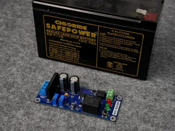
Thermostat with Thermistor NTC
Circuit description
The temperature dependence of the temperature thermistor can be:
- with negative temperature coefficient - NTC (Negative Temperature Coefficient), in which case the resistance of the thermistor decreases to
temperature rise;
- with positive temperature coefficient - PTC (Positive Temperature Coefficient), in which case the resistance of the thermistor increases to
temperature rise.
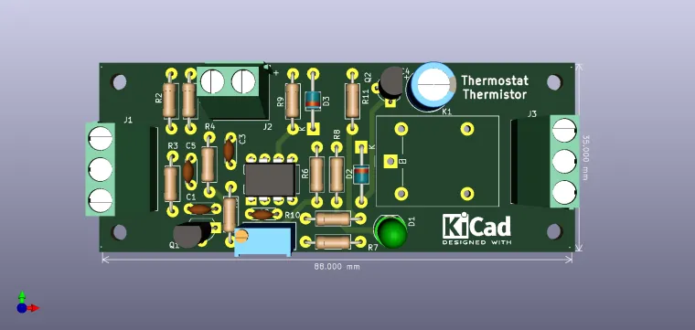
The diagram uses an NTC thermistor as a temperature transducer, it is connected to J1, pins 1 and 2, pin no. 3 being the shielding, in case. When growing temperature resistance value decreases, so the voltage on the collector Q1 will increase, voltage that will be applied on
the inverter input of U1. Operational U1 with the role of comparator will notice the voltage threshold set by RV1 on the non-inverting input and will block the transistor Q2 which has as load relay K1. Conversely, as the temperature decreases, the value of the resistance the thermistor will increase, the voltage on the collector Q1 will decreased so that, for the value set by RV1, the comparator will command through Q2 the coupling of relay K1. C1 and C3 have the role of filtering noise on the line and provide stability to sudden variations in the values ??of the respective thermistor RV1, C2 integrates the measured signal on the input and C4 creates a hysteresis to avoid disturbing triggering around prescribed value. The temperature can be raised to 180 ° C without notice thermistor depreciation, the only notable thing being that hysteresis increases slightly with temperature. Using a small thermistor, sensitivity grow. The gradation of the scale will be done using a standard thermometer
and a container of liquid at various temperatures. It`s a simple circuit, but one that can give great results in operation.
Note: J1 is used to connect the thermistor (Pin no.1 is +V and Pin no.2 is S, Pin no.3 is the shielding (connected to GND), not necessary in some cases); J2 is for powering the circuit (Pin no.1->+12V ; Pin no.2->GND); J3 represents the relay`s contacts (Pin no.1->NO ; Pin no.2->NC ; Pin no.3->Common)
Enjoy it!


